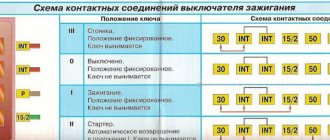
To check the ignition switch, sequentially set the key to the positions at which the circuits indicated in the table should be closed.
When the key is turned to position “III”, the anti-theft device should be activated. When turning the key from position “III” to position “0”, the anti-theft device should turn off. This can be checked by turning the steering wheel.
When restarting from position “I” to position “II”, the locking is activated. The key can only be turned to position “II” from position “0”.
If there are defects, replace the contact group or ignition switch
Live contacts
Outdoor Lighting. Instrument lighting. High beam headlight alarm
Generator excitation winding. Ignition system. Windshield cleaner. Carburetor idle speed solenoid valve control unit. Direction indicators. Reversing light. Control devices
Low and high beam headlights. Fog light. Headlight cleaners. Rear window cleaner. Heated rear window. Washer. Heater fan. Engine cooling fan
1.
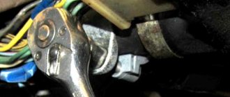
Unscrew the six screws securing the lower steering column casing of the VAZ 21099.
2.
Remove the lower steering column cover.
3.
. and ignition switch trim
4.
Remove the upper steering column cover.
5.
Disconnect the ignition switch wiring harness from the wiring harness.
6.
Disconnect the block with the ignition switch wires from the ignition relay for the Lada Satellite.
7.
Insert the key into the ignition switch of the VAZ 2109 and turn it to position “0” to turn off the anti-theft device. Unscrew the four mounting bolts (two bolts are located on top of the column). Remove the bracket and ignition switch for the Lada Samara (see notes 1 and 2).
If the bolt heads are sheared off, the bolts must be drilled out or removed using a screwdriver and hammer.
An ignition switch is installed on the part, secured with two bolts. There is a slot at the top of the bracket that accepts the hook on the ignition switch housing.
8.
Unscrew the screw securing the switch cover.
9.
Remove the switch trim by pressing out the two plastic latches with a screwdriver.
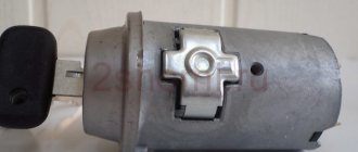
10.
Remove the contact group.
11.
Assembling and installing the VAZ 2108 ignition switch is carried out in the reverse order.
Malfunctions of the ignition switch VAZ 2109
Malfunctions of the ignition switch of the VAZ 2109 are quite common. This element consists of two parts: mechanical and electrical. Because of this, malfunctions of the ignition switch on the VAZ 2109 can pose a big problem for many, which they cannot cope with on their own. This publication aims to familiarize the reader with all known malfunctions of the ignition switch and explain how to fix them.
What is
First, let's look at the structure of the castle. Let's find out what it looks like, what it consists of, what its operating principle is, and so on:
- As mentioned, the ignition switch is a very important element of the VAZ 2109 car, because almost all available equipment is connected to it.
Note. Although there are components that do not depend on the lock in any way. Here they are: license plate lights, brake lights, parking lights, hazard lights, interior lights and lights on the dashboard.
- There are different types of ignition switches: new or old type. The first version without a relay has three positions and a short key, the second with a relay has four positions and a long key.
VAZ 2109 ignition switch malfunction
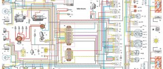
Scheme
Below is a typical diagram of the ignition switch on the “nine”.
| In key position “0” | The VAZ 2109 is de-energized, and there is power only in the wires that go directly to the battery |
| In key position “1” | The following car components are working: external lighting, headlights, instrument lighting, interior light, all control devices, wipers, heated windows, etc. |
| In position “2” | The starter turns on and all position “1” circuits work |
| In position “3” | All circuits including brake light |
Typical faults
VAZ 2109 ignition switch
The lock belongs to the car's ignition system. Let us note right away that if problems are observed, you can fix them yourself, because, as a rule, the “nine” is equipped with an outdated ignition system that does not require diagnostics and repair at a service station.
How to make sure there is a problem
Below is a tip on how to make sure that the ignition switch is really not working:
- We insert the ignition key and turn it to a certain position. A short circuit in the circuit must necessarily occur. We look at the diagram: if the key is in position “1”, is the external lighting or control devices working;
- It is recommended to check at all positions of the lock. If deviations from the norm are observed, there is a problem with the lock;
- You can also check the functionality of the ignition switch in the following way: turn the steering wheel, which should not be blocked. The lock on a working steering wheel should only work when the key is turned a second time from position “1” to position “2”;
Installing a new device
Now you can finally proceed directly to replacing the broken or worn out ignition switch on your VAZ2114 car.
To do this, follow the following sequence of actions:
- Insert the key into the new lock and turn it to the first position. This will allow the latch, which is responsible for locking the steering shaft, to hide inside the housing structure;
- Insert the lock into place following the reverse dismantling sequence;
- Install the four retaining bolts and tighten them slightly.
Repair and replacement
Typically, the lock can be repaired. If this fails, you will have to completely replace it (see Replacing the VAZ ignition switch on your own). Repairing a lock in most cases comes down to replacing the cylinder or contact group. If after this the problem has not been resolved or it is possible to change the entire lock, then it is better to do the latter.
VAZ 21093 ignition switch
Larva and its replacement
So, we do the following:
- Remove the steering column cover and unscrew the fastening bolts that tighten the ignition switch clamp.
Note. The bolts have sheared heads and then you will have to use a hammer and chisel. The bolts are first loosened by blows with a chisel, and then unscrewed with pliers.
- We separate the two parts of the clamp so that they disengage;
- The larva can be changed already at this stage of the operation;
- We take out the side pin that holds the cylinder in the lock.
Advice. The cylinder can be easily removed with a thin screwdriver, for example, from a watch. At the same time, you need to tap the lock with a hammer.
- If you cannot pull out the cylinder after the side pin has been removed, you can try to drill out the cylinder using a thin drill;
- If again it was not possible to remove the cylinder, then it is recommended to finally remove the lock;
- Remove the wire plugs.
Note. One of the plugs (the one with the larger connector) is located under the dashboard. To remove it, you need to put your hand under the panel.
- If the ignition switch has a relay, then take it out from under the panel;
- Disconnect the connector;
- We also remove the ground wire;
- Remove the cover by pressing the latch, and then the contact group;
- Now it will be much easier to remove the larva;
- We replace it with a new one;
- We check the work on site before putting everything back into place. We turn the key inside the lock - all the processes described above should work.
Note. Don't forget to also check that the steering wheel lock works. If the steering shaft does not lock when the steering wheel is turned completely, we adjust the correct location of the lock on the column.
- After a thorough check, making sure that everything works correctly, tighten the bolts until the heads come off. It is advisable to use the key at “10”.
contact Group
Lock contact group
Replacing the contact group of the lock, if this is the fault of the lock, is the most profitable from the point of view of monetary costs. The actions boil down to removing the lock (how to do this is written above). Here are some guidelines to follow:
- Before disconnecting contacts, you need to number them to avoid confusion;
- Some models of locks in the contact group design have a retaining ring, which must first be removed. This is most easily done using an awl.
Preparation
At the preparation stage, you will need to collect the necessary tools near you, which will be useful in the process of dismantling and installing a new ignition switch. You will also have to remove the steering cover and steering column shifters. Doing this is quite difficult, but we will tell you step by step about all the nuances of these preparatory activities. So you can easily figure out for yourself how to remove the ignition switch on a VAZ 2114.
Tools you will need:
- Phillips strong screwdriver;
- Open-end wrench 10 millimeters;
- Chisel;
- Hammer;
- Pliers or pliers;
- New ignition switch assembly;
- Lock mounting screws (4 pieces).
Now let's move on to the casing and switches. For more convenient work, many advise removing the steering column switches and the steering wheel itself. Dismantling the casing is performed in the following sequence:
- Disconnect the negative cable from the battery. Nobody has yet canceled the requirements for personal safety and protection against electric shocks;
- Unscrew the three screws securing the two parts of the casing. A screwdriver is useful for this;
- Unscrew the screw that connects the housing to the connector of the steering column switches;
- Remove the two screws that hold the lower housing to the steering column;
- The lever that fixes the column at the corner leads down;
- The steering wheel also goes down;
- The lower casing is then removed;
- The power supply from the emergency lights must be disconnected;
- Now you can remove the top casing;
- To dismantle the steering column switches, you need to act one by one;
- Simultaneously press both latches and thereby remove the elements from their seats;
- Disconnect them from the power supply.
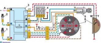
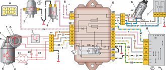
Wiring diagram for the ignition switch on the VAZ-2108, 2109 and 21099
Wiring diagram for the ignition switch on the old-style VAZ-2108, 2109 and 21099 with an unloading relay.
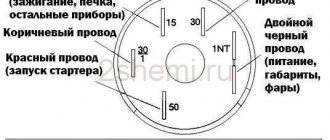
Pinout of the VAZ-2109 ignition switch with unloading relay:
- comes +12V in position I, II, III (parking)
- comes +12V in position I, II, III (parking)
- comes +12V in position III (parking)
- position I, +12V goes out after turning on the ignition (contact 15/2), disappears at start (II);
- position I, +12V goes to the starter (pin 50);
- position I, +12V goes away after turning on the ignition (pin 15), does not disappear when starting II;
- +12V comes from the battery (pin 30);
- comes +12V constantly.
Wiring diagram for the ignition switch on the VAZ-2108, 2109 and 21099 of the new model, without a relay.
Pinout of the new VAZ-2109 ignition switch:
- comes +12V constantly
- comes +12V constantly
- +12V arrives after turning on the ignition (pin 15), does not disappear when starting II;
- +12V arrives after turning on the ignition (contact 15/2), disappears at start (II);
- position I, +12V goes to the starter (pin 50);
- +12V arrives after turning on the ignition (pin 15), does not disappear when starting II;
- +12V comes from the battery (pin 30);
- comes +12V constantly.
Photo 1, pinout of the new VAZ 2109 ignition switch
Photo 2, pinout of the new VAZ 2109 ignition switch
Testing the serviceability
The lock's service life is limited. After it fails, it is necessary to repair or completely replace the product. The functionality is checked after inserting the key into the “secret”.
Failures occur due to mechanical wear or loss of contact. The check is carried out by turning the key. If it begins to jam, then as a temporary solution it is possible to use silicone grease by dripping it inside.
In order for the wiring diagram to function correctly, you need to know which contacts to connect to each other. Typically the following wiring system is used:
- red connects to the cable from the starter;
- the pink wire goes to “+” from the 12 V battery;
- brown +12 V is used to start the ignition relay;
- white – relay on;
- black and blue connect other consumers.
It is necessary to check the contacts for the presence of carbon deposits or the possibility of oxidation. Burning contacts can be heard in the cabin by the characteristic smell of burnt insulation.
Ignition switch VAZ 2109 faults
The ignition switch of the VAZ 2109 is a very important and at the same time very capricious mechanism of the car. And in today’s article we will try to analyze its importance and capriciousness, i.e. its malfunctions. The ignition switch serves to supply voltage to electrical circuits depending on the location of the key. The castle consists of 2 parts. These are the mechanical and electrical parts.
As has already been written, in our nine the ignition switch is a very important mechanism. Almost all of the car's electrics pass through it. Without an ignition switch, only a few devices can operate and these are:
1. Side lights.
2. Emergency alarm.
3. Interior lighting.
5. Rear number plate illumination.
This is necessary so that when stopping on the highway or in the city in an unlit place, we do not need to turn on the ignition in order to be noticed.
The ignition switch of the VAZ 2109 is faulty.
The most common problem with the ignition lock is its working out and jamming. If these symptoms occur, you should immediately replace the entire ignition switch, because in case of jamming, you can simply burn the starter and then the repair will cost you the cost of the starter. Another common problem is the failure of the contact group. In this case, several devices fail at once. For example, my low beam headlights, heater, cigarette lighter, and rear window heater immediately stopped working. Replacing the contact group with a new one, everything worked immediately.
Changing the contact group
Exploded view of the lock
From a cost point of view, replacing one contact group is the least expensive:
- All our actions are repeated in principle, as in the case described above with removing the lock, you will have to remove the casing, and so on
- To avoid the common nuisance associated with mixing up contacts, it is recommended to number them (or otherwise mark them) before disconnecting them.
- This measure will save your nerves and time
- Some models of locks have a locking ring in their contact group, and here we need an awl to remove it
- It’s important not to forget to put it back in place later.
- Then everything is assembled back and screwed to the steering column
That's all, all that remains is to finish watching the video and calmly change any part of the lock.
A little theory
The ignition switch must switch, that is, connect contacts that supply power to different electrical circuits. The voltage from the battery is supplied to the “30th” contact of the lock, and sometimes two lines are used: “30/1” and “30/2”. Each line is equipped with a 30 Ampere fuse, hence the well-established name.
30 amp fuse painted green
When turning the key, the "30 pins" are usually connected to the following:
- In the “Parking” position – to the “INT” contact, from which current is supplied to additional equipment;
- “Ignition” – to the “INT” contact, also to contacts “15/1” and “15/2”;
- “Start” – to contact “15/1”, but not to “15/2”, as well as to contact “50”.
From terminal “50” power goes to the starter solenoid relay. The “15th” contact, in turn, feeds the main ignition circuit. And if there is an additional circuit, it will be open when the starter operates.
Let us note once again: when the key is set to the “Start” position, contact “15/2” does not receive a positive potential. This is true for all cars of any model, including the VAZ Nine.
Steering lock testing
If you don't check the steering lock, you may encounter certain problems in the future. Therefore, do not waste your time on this event. It consists of removing the key from the ignition and turning the steering wheel at a slight angle.
- If there is no lock, you will need to slightly adjust the position of the lock. Make sure it fits into the groove located on the steering shaft.
- If the locking is effective, you will only need to tighten the four installed breakaway bolts until they stop. Twist until the heads break.
When the lock installation is completed and the test has passed, do not forget to connect the device to power and start the engine. If it starts, all systems dependent on the ignition switch are working, you can fully begin reassembly. Follow the reverse instructions for removing the casing and steering column switches. It would not be amiss to check the condition of certain nodes along the way. It is quite possible that some of them also need replacement or a little preventive maintenance.
“Classics”, as well as the “Ninth” family
Fiat engineers, when developing the ignition switch for their 124 model, used two supply lines (“30” and “30/1”). The ignition line was the only one.
Connecting the VAZ-2101 lock terminals 5 terminals on the lock module Connecting the VAZ-2109 ignition switch (color coding)
Another ignition circuit containing contact “15/2” was added during the transition to the “2109” family. It, in turn, is switched using a relay. In different families, only the diagram differs, but not the “behavior” of the car when the key is installed opposite the marks:
- Position 0: everything is off;
- Label 1: ignition and engine operation;
- Mark 2: starting the starter;
- Label 3: “Parking” mode.
To turn off the engine, turn the key to position “0”. The spark plugs lose spark and the engine stops.
The ignition switch module, if we talk about the “classic family”, is equipped with 5 terminals (see Fig. 2). Starting from the “2109” family, this solution is not used. Several wires come out of the lock cylinder and are connected to a remote connector.
The connector layout can be easily identified using the color coding (see diagram above). When carrying out any installation work, remember the following: you must turn off the engine, open the hood and disconnect one of the battery terminals. Usually the negative one is turned off.
Exactly three switched contacts
One line through which current is supplied, and only one ignition circuit - this solution is typical for all VAZ cars, if we talk about the “2110”, “2170” and later families. Even in Grants, produced since 2012, the additional ignition circuit did not appear. In general, with the transition to the “Ten” family, three “significant” terminals of the lock remained:
- Contact "30";
- Terminal “15” (can be designated as “15/1”);
- Terminal "50".
The ignition switch circuit looks trivial, even if we talk about the Lada 2110.
Ten and its ignition switch, diagram Diagram and connector of the ignition switch of modern models Ignition switch connector Tens
The Tens connector has 8 terminals. And in Priora, as well as in Grant and Kalina, this number is reduced to three (Fig. 2).
Of the 8 terminals available in the VAZ-2110 connector, the 7th and 8th simply duplicate each other. Two more are connected to the button, and another pair of terminals are connected to the lamp.
The lock connector of all VAZ models, starting from “2170”, is equipped with only three contact terminals. And the additional connector, which is equipped with a pair of terminals, is connected to the immobilizer in these cars.
The “3” mark has disappeared from the “Tens” lock cylinder. And until now, VAZ produces just such locks, where the key can be installed in one of the following positions:
The presence of the “Parking” mode, as you can see, is not provided here.