But if connecting the wires together did not result in the starter operating (or it did not turn on the first time), check the solenoid relay on the starter. The contact spots on it may also burn out, which will prevent the circuit from closing normally. Alternatively, you can use a screwdriver to short-circuit the two large terminals on the solenoid relay (before doing this, put the car in neutral and use the handbrake). When closed, the starter should begin to spin vigorously. If this happens, remove and change the solenoid relay. If the starter rotates “sluggishly” when it closes, you will have to remove it and check the condition of the brushes.
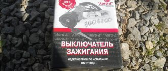
All operations are performed with your own hands, without the help of car service specialists. Moreover, the price of an ignition switch on a VAZ2106 is up to 100 rubles. To replace it, you will need to know the pinout of the wires coming from it, for which the editors of the site 2 Schemes.ru have prepared a large reference material.
The ignition switch is designed not only to start the engine - it performs several functions at once:
- supplies voltage to the vehicle’s on-board network, closing the circuits of the ignition system, lighting, sound alarm, additional devices and instruments;
- at the driver’s command, turns on the starter to start the power plant and turns it off;
- turns off the power to the on-board circuit, preserving the battery charge;
- protects the car from theft by fixing the steering shaft.
Pinout of the ignition switch VAZ-2101 - VAZ-2107
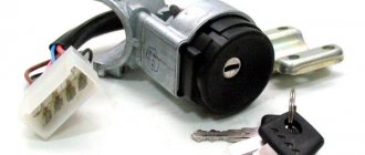
The ignition switch on these cars is located to the left of the steering column. It is fixed directly to it using two fixing bolts. The entire mechanism of the device, except for the upper part in which the keyhole is located, is hidden by a plastic casing.
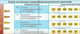
On the visible part of the ignition switch housing, special marks are applied in a certain order, allowing inexperienced drivers to navigate the lock activation mode when the key is in the hole:
- “” – a mark indicating that all systems, devices and instruments that can be turned on using the lock are turned off (this does not include the cigarette lighter, interior lighting, brake light, and in some cases the radio);
- “ I ” is a mark informing that the vehicle’s on-board network is powered from the battery. In this position, the key is fixed independently, and electricity is supplied to the ignition system, to the electric motors of the heater and windshield washer, instrumentation, headlights and light signaling;
- “ II ” – engine start mark. It indicates that voltage is applied to the starter. The key does not lock in this position. If you release it, it will return to the "I" position. This is done so as not to subject the starter to unnecessary loads;
- “ III ” – parking mark. If you remove the key from the ignition in this position, the steering column will be locked with a latch. It can only be unlocked by inserting the key back and turning it to position “0” or “I”.
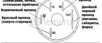
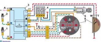
The ignition switch has five contacts and, accordingly, five terminals, which are responsible for supplying voltage to the desired unit. All of them are numbered for convenience. Each pin corresponds to a wire of a certain color:
- “50” – output responsible for supplying current to the starter (red or purple wire);
- “15” – terminal through which voltage is supplied to the ignition system, to the electric motors of the heater, washer, and instrument panel (double blue wire with a black stripe);
- “30” and “30/1” – constant “plus” (pink and brown wires, respectively);
- “INT” – external lighting and light signaling (double black wire).
Connection
Now about the connection. If the wires are assembled into a chip, then there will be no difficulties - we install the chip correctly on the contacts and that’s it.
If each wire is connected separately, then you need to follow the diagram:
- To pin 50 – red wire (responsible for the operation of the starter);
- To pin 15 – blue with a black stripe (ignition, interior heating and other devices);
- Pin 30 – pink wire;
- Pin 30/1 – brown wire;
- INT – black wire (dimensions and headlights);
After connecting the wiring, everything is assembled, the terminal is connected to the battery and the functionality is checked. First you need to check whether all electrical appliances powered by the lock are working. Then check the functionality of the starter.
If something does not work, you need to remove the lock and once again check that the wiring is connected correctly, since this alone determines the operation of the devices when you turn the key.
Pinout of lock VAZ-2108, VAZ-2109, VAZ-21099
Pinout according to the old type
Pinout of the VAZ-2109 ignition switch with unloading relay:
- comes +12V in position I, II, III (parking)
- comes +12V in position I, II, III (parking)
- comes +12V in position III (parking)
- position I, +12V goes out after turning on the ignition (contact 15/2), disappears at start (II);
- position I, +12V goes to the starter (pin 50);
- position I, +12V goes away after turning on the ignition (pin 15), does not disappear when starting II;
- +12V comes from the battery (pin 30);
- comes +12V constantly.
New pinout type
Pinout of the new VAZ-2109 ignition switch:
- comes +12V constantly
- comes +12V constantly
- +12V arrives after turning on the ignition (pin 15), does not disappear when starting II;
- +12V arrives after turning on the ignition (contact 15/2), disappears at start (II);
- position I, +12V goes to the starter (pin 50);
- +12V arrives after turning on the ignition (pin 15), does not disappear when starting II;
- +12V comes from the battery (pin 30);
- comes +12V constantly.
How to remove the lock
Be sure to remove the negative terminal from the battery. Some car enthusiasts do not do this, explaining this by low circuit voltage. However, if the wires short out during repair work, this will lead to malfunction of some electrical equipment elements. Turn the key to the zero position. This will make it easier to dismantle the device due to the fact that the steering wheel holding shaft will fit slightly into the secret part. Remove the steering column cover. To do this, unscrew the five screws connecting the top and bottom of the casing
Pull the upper part of the casing up, acting very carefully. We remove and put away all the elements of the casing. Having removed the casing, unscrew the screws that secure the lock itself.
There are two of these screws, they are located below the switch.
Disconnect the wires from the lock.
In order not to break the latch during dismantling, we find a small gap on the left side of the bracket. We insert an awl or a thin nail into it and press the latch.
Use a slotted screwdriver to remove the mechanism from the bracket.
Another important tip: mark how the wires were connected. This will help you avoid any confusion when installing a new device.
Pinout of lock VAZ-2110, VAZ-2111, VAZ-2112
Pinout of the ignition switch VAZ-2110:
- comes +12V for the microphone of the sensor of the inserted key;
- the mass comes when the driver's door is open;
- +12V goes to the starter (pin 50);
- +12V goes out after turning on the ignition (pin 15);
- +12V goes out when the key is inserted to pin 5 of the BSK;
- comes +12V to illuminate the lock cylinder;
- +12V comes from the battery (pin 30);
- not used.
Useful: USB - A, B, C and D: pinout, speed and connection features
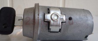
Design
Before connecting the ignition switch to the VAZ-2101, you need to familiarize yourself with its design. The node includes three blocks:
- “secret” with a central tunnel;
- pins designed to hold the steering column from turning;
- contact Group.
The contact chips are installed in the rear of the cylinder. The larva is hidden by a metal shell.
Due to the unique “secret”, additional protection against car theft is provided . When the key penetrates into the cylinder all the way, it becomes possible to turn it, thereby closing the necessary contacts. In this way, each rotation angle can be unique.
The anti-theft unit is also used in subsequent models. The principle of its operation is quite simple, as it is based on mechanics. When the key is removed from the “secret”, due to the spring, the steel pin moves into the groove, fixing the steering wheel and, accordingly, the wheels in a single position.
The contact group acts as an electrical switch. It rotates following the slider coming out of the mechanical part of the lock, closing and opening the contacts in steps.
Pinout of lock VAZ-2113, VAZ-2114, VAZ-2115
Pinout of the ignition switch VAZ-2113, 2114, 2115:
- comes +12V for the microphone of the sensor of the inserted key;
- the mass comes when the driver's door is open;
- +12V goes to the starter (pin 50);
- +12V goes out after turning on the ignition (pin 15);
- +12V goes out when the key is inserted to pin 5 of the BSK;
- comes +12V to illuminate the lock cylinder;
- +12V comes from the battery (pin 30);
- not used.
Occurring faults
The design of the lock is quite simple and reliable, but the lock may well break. There are only two malfunctions that can happen to this element: mechanical and electrical.
A mechanical failure includes a problem with the secretion. Due to debris that gets inside the secretion and moisture, corrosion is formed, which prevents the movement of moving elements inside the secretion. As a result, the lock begins to jam when you turn the key, jams, or stops rotating altogether. This problem can be eliminated by pouring WD-40 or at least brake fluid inside. However, if it is possible to restore the functionality of the secret in this way, it will not be for long. The secret itself is not repairable, and in the event of such a malfunction, the VAZ-2101 ignition switch will eventually need to be replaced.
An electrical fault is the burning of the nickels of the contact group. Because of this, there will be no or insufficient contact between the runner and the nickel. Electrical appliances on the car will not work, and there may be no power supply to the starter. If the burning was minor, then you can try to restore the functionality of the lock by cleaning the nickels with a diamond file, followed by wiping with alcohol or gasoline. But if the nickels are badly burnt, then you will need to either change the contact group or the lock assembly.
An interesting article about biofuel produced from ordinary sawdust, read more here.
The structure of a car ignition switch
- Locking rod
- Frame
- Roller
- Contact disc
- Contact sleeve
- Block
- Protrusion of the contact part.
The lock mechanism is connected to many wires. They continue from the battery, connecting all the electrical devices of the car into a single chain. When you turn the ignition key, the electrical circuit is closed from the “-” terminal of the battery to the ignition coil. As a result, the current passes through the wires to the ignition switch, through its contacts it is directed to the induction coil, after which it returns back to the “+” terminal. As electricity passes through the coil, it generates high voltage, which it transmits to the spark plug. Therefore, the key closes the contacts of the ignition circuit, thereby starting the car engine.
Replacing the lock cylinder itself or the contact group
Read
Replacing the VAZ 2109 lock cylinders requires the following tools:
In case of any breakdown, it is not necessary to completely replace the lock; if the cause of the malfunction lies in replaceable parts, then a partial repair of the lock is carried out and replacing the lock cylinders on the VAZ 2109 makes sense when the key stops spinning freely in the keyhole. Another option for partial repair is to replace the contact group; this requires a minimum of tools and little understanding of the device.
Our summary will help you understand the device:
- Nothing and no one forbids you to change the entire lock every time, and even go to a service station if you are satisfied with the price
- After removing the casing, access to the switch lock is revealed.
- In principle, the lock cylinder can already be removed at this step
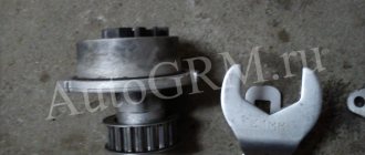
- Therefore, we pull out the side pin that holds it in the lock
- This is easy to do with a narrow screwdriver (clockwise) while tapping it with a small hammer
- If the pin cannot be pulled out this way, then try to carefully drill out the cylinder using a narrow drill
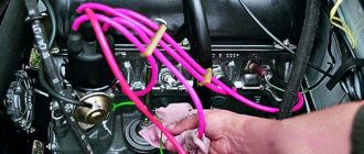
- If it is more convenient for you to pull it out first, pull out the ignition switch, before you start replacing the cylinder, to do this you need to unscrew the bolts securing the ignition switch to the control column
- This must be done using a hammer and chisel because these bolts have sheared heads.
- You need to loosen them a little with a chisel, and then unscrew them with pliers, as in the photo below
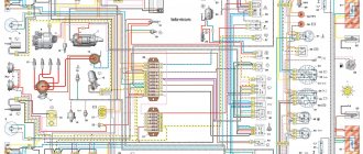
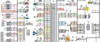
Electrical diagram of VAZ 2104
The electrical equipment of the machine is protected by fuse links installed in the mounting block. The battery charging circuit, ignition and engine start circuits, and the high and low beam relay windings are not protected by fuses. Before replacing a blown fuse link, correct the problem that caused the fuse to blow. When looking for a problem, I advise you to look at the circuits that protect this fuse.
In cars produced before 1988, the fog lights in the rear lights and the fog light warning lamp were protected by fusible insert No. 17 of the mounting block. Since 1988, they have been protected by a separate fuse in the wiring harness near the fog light switch. This insert is designed for current flow up to 8A.
Until 1988, the glove compartment light was protected not by fuse No. 15, but by a second fuse. All fuses and various auxiliary relays were mounted in a separate block in the engine compartment. Also, through the mounting block, the wiring harnesses of the engine compartment are connected to the dashboard harness and to the rear harness.
The mounting blocks are quite easy to disassemble and repair. The old-style block (with finger inserts) consists of two parallel-connected printed circuit boards; the new-style blocks (with knife inserts) have one board. Soldering of wires is allowed in case of bypassing burnt-out tracks on printed circuit boards, but only if this does not require disconnecting the PCB.