Site about SUVs UAZ, GAZ, SUV, CUV, crossovers, all-terrain vehicles
To control the fuel supply, the UMZ-4216 engine of Gazelle and Sable cars is equipped with an absolute pressure sensor, a crankshaft position sensor (frequency sensor), a camshaft position sensor (phase sensor), coolant and intake air temperature sensors.
Sensors of the UMZ-4216 engine control system on Gazelle and Sobol cars, switches and relays, designation, placement and purpose.
The fuel supply control system of the UMZ-4216 engine on Gazelle and Sobol cars also uses an oxygen sensor (lybda probe), on the UMZ-4216 Euro-2 engine there is one, it is installed in the engine exhaust system on the exhaust pipe of the muffler in front of the converter. And two oxygen sensors on the UMZ-4216 Euro-3 engine, the second is installed after the converter.
Electrical diagram of the UMZ-4216 engine control system with electronic fuel injection.
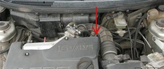
Location of sensors for the UMZ-4216 engine control system with electronic fuel injection.
Absolute pressure sensor SIEMENS ATRT SNSR-0239 or A2C53257696.
The sensor is strain gauge, with a built-in air temperature sensor. The sensor is installed in the receiver and is designed to measure the pressure in the receiver, which changes depending on the load, and at the same time determine the temperature of the air entering the engine. The sensor consists of a diaphragm and an electrical circuit that changes its resistance in proportion to the pressure in the receiver.
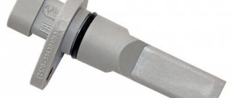
Crankshaft position sensor - frequency sensor 23.3847 or 406.387060-01.
The sensor is of inductive type, works in tandem with a synchronization disk having 60 teeth, two of which are removed. The cutting of the teeth is a phase mark of the position of the engine crankshaft. The beginning of the 20th tooth of the disk corresponds to TDC of the first or fourth cylinders of the engine. The counting of teeth begins after cutting along the direction of rotation of the crankshaft.
The sensor serves to synchronize the control phases of the system's electrical mechanisms with the operating phases of the engine's gas distribution mechanism. Installed at the front of the engine, on the right, on the flange of the camshaft gear cover. The nominal gap between the end of the sensor and the tooth of the synchronization disk should be in the range of 0.5-1.2 mm. The sensor is connected to the wiring harness using a three-pin socket with a latch.
Camshaft position sensor - phase sensor BOSCH 0 232 103 006 or 406.3847050-01.
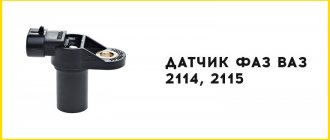
Integrated sensor based on the Hall effect (or magnetoresistive effect) with a built-in amplifier - signal conditioner. The sensor works in conjunction with the camshaft marker pin. The center of the camshaft marker pin coincides with the center of the first tooth of the timing disk. The sensor serves to determine the TDC phase (top dead center) of the first cylinder, that is, it allows you to determine the beginning of the next engine rotation cycle.
The sensor is installed in the front of the engine, on the left, on the camshaft gear cover. The nominal gap between the end of the sensor and the marking pin should be in the range of 0.5-1.2 mm. The sensor is connected to the wiring harness using a three-pin socket with a latch.
Throttle position sensor BOSCH DRG-1 0 280 122 001 or 406.1130000-01.
The sensor is a potentiometer with a current collector. Serves to determine the degree and rate of opening of the throttle valve. On the throttle body there are fittings with a diameter of 8 mm for supplying and discharging coolant to heat the throttle device, as well as pipes for connecting the main branch of the crankcase ventilation system and the idle speed regulator.
Checking the serviceability of the throttle position sensor on UMZ-4216 engines.
During operation, the throttle device does not require any maintenance, however, in case of problems in the power system, especially when the engine is unstable in idle mode, you should check the operation of the throttle position sensor. To do this, with the engine off, disconnect the wiring harness block from the plug connector on the specified sensor. A DC source with a voltage of 5+-0.1 V is connected to connector pins 1 (plus) and 2 (minus).
With the throttle valve closed, the output voltage taken from pins 3 (plus) and 2 (minus) should be in the range of 0.26-0.68 Volts; with the throttle valve fully open, the voltage should be 3.97-4.69 Volts. The accuracy class of the voltage measuring device must be at least 1.0. If the voltage deviates from the specified limits by more than 10%, the throttle position sensor must be replaced.
Coolant temperature sensor 234.3828.
It is a sensor with a thermistor element. Serves to monitor the thermal state of the engine. The temperature sensor is installed on the engine coolant pump housing (front). The connection of the temperature sensor to the wiring harness is made using two-pin plug sockets with latches.
Oxygen sensors - lambda probe 25.36889.
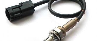
To ensure modern Euro-2 and Euro-3 exhaust gas toxicity standards, one (Euro-2) or two (Euro-3) oxygen sensors 25.36889 (lambda probe) are installed in the UMZ-4216 engine exhaust system on Gazelle and Sobol cars. The main sensor is installed in the engine exhaust manifold and is designed to determine the composition of the mixture before the converter. An additional sensor is installed on the converter body, at the exhaust gas outlet, and is designed to determine the composition of the mixture after the converter.
Zirconium oxygen sensors with controlled electrical heating. The oxygen concentration in the exhaust gases is determined. Their signals allow the engine control unit to maintain the required composition of the fuel mixture for the most optimal engine operation. Oxygen sensors have a non-separable design and do not require maintenance. The sensors are connected to the wiring harness using a 6.3 series socket (signal wire) and a two-pin plug with a latch (the posistor sensor heater circuit).
Rough road sensor 28.3855000.
Rough road sensor 28.3855000 piezoelectric. Located on the right, in the direction of travel, frame side member under the air filter. The sensor measures the acceleration that occurs when the vehicle moves on an uneven road. Designed to detect vehicle body vibrations transmitted to the transmission and engine, and take these vibrations into account when identifying misfires.
Causes of problems
clutch adjustment gazelle business engine 4216
The air flow meter becomes unusable for the following reasons:
- a lot of dust and dirt gets on the measuring elements, because the car owner rarely changes the air filter;
- on heavily worn engines, gasoline and oil vapors penetrate into the mass air flow sensor through the crankcase ventilation pipe;
- a hole in the corrugated air duct from where dust is sucked in;
- accidental damage due to unqualified repairs;
- break in the wires connecting the sensor connector to the controller.
In addition to the above reasons, natural wear and tear of the device also occurs. The service life of a new mass air flow sensor is 50–250 thousand km, depending on the make and origin of the car.
Purpose and operating principle of DPKV
The function of the device is to determine the position of the engine cardan at a certain time for computer control of actuators and coordination of the functioning of the gas distribution system. It serves to ensure the formation of impulses from the (60-2) teeth of the disk, that is, it marks the rotation of the cardan on sector marks. The angular stroke of one tooth, together with the gap to the next, is equal to 6 o of rotation of the cranked spindle. It functions in conjunction with a toothed circle located on the cardan pulley. The circle has 60 notches with 2 whole protrusions missing. The cutout on the circle serves as the starting point for the location of the crankshaft. The beginning of the 20th (behind the cutout) tooth (teeth numbering starts from the cutout clockwise) corresponds to TDC of the first or fourth cylinder.
The specificity of the action of the crankshaft sensor is the formation of an alternating current emf of a sinusoidal type in its coil when passing a metal tooth of a circle with protrusions near its end. In the middle of the protrusion (its rear cut) there is zero pulse amplitude. When passing the cutout of the gear circle, the device is silent. From this point the car computer starts counting. When the 20th notch of the ECU synchronization circle approaches, it marks the location of the pistons of the first or fourth pots at TDC. Thus, the car computer knows what is located where in the engine.
Failure of the DPKV leads to the engine stopping.
Attention! The crankshaft sensor is the most important sensor among all engine sensors. You need to have a intact, working, spare DPKV in your car.
How the speedometer works
Before we tell you how to adjust or wind up the odometer readings, let’s figure out what the operating principle of the speedometer on a Gazelle is. The principle of operation of the mechanism is to measure the speed of the vehicle through the mechanical connection of its pointer with the output pulley of the gearbox. The latter receives wheel drive.
The shaft can give a true measure of driving speed; more accurate indicators will give the wheels of the car. This is because the gearbox pulley is located further from the gearbox and closer to the wheels, and the speed at which it rotates is set in accordance with the final speed after the gearbox. The speed of rotation of the pulley may be identical in both first and fourth gear, but the difference in the speed of the machine can be colossal.
In a gearbox, the output pulley contains a gear that rotates with the pulley. The gear is connected to the speedometer drive cable. In the circuit, the cable is a durable wire located inside a protective rubberized casing. One end of the cable is installed in a special hole and fixed on the drive gear. When the gear rotates, the cable rotates with it.
The second end of the cable is connected to the device on the control panel. At the end is a magnet in the shape of a shaft, which is mounted close to the steel drum, but not in contact with it. The drum is attached to the needle and transmits readings to the corresponding scale. When the vehicle is stationary, the cable needle is kept at zero level by a small coil spring.
Scheme for making a twister
Technical characteristics of the crankshaft sensor 23.3847
This section indicates the location of the crankshaft sensor for engines 405, 406, 409, 4213, 4216. The specific installation point for the device is presented.
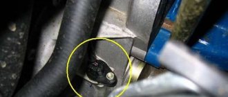
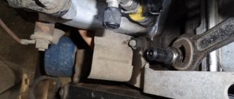
It is mounted in the front of the heart of the car, on the right, below on the protrusion of the front cover of the cylinder block. Attached with M6 hardware under head 10. The normal gap between its end and the tooth of the synchronization disk should be 0.5-1.2 mm. For stable operation, set the gap to 0.8 mm. To do this, you need to sand the device seat with sandpaper. The crankshaft sensor is connected to the wiring harness using a three-pin socket with a frame spring.
Where is the DPKV installed on the UMZ 4213, 4216 engine?
The crankshaft sensor is located in the front part of the engine, on the right, on the flange of the camshaft gear cover. The nominal gap between the end of the device and the tooth of the synchronization disk is in the range of 0.51-2 mm.
Adjusting the lifting mechanism
It is necessary to periodically check the condition and correct adjustment of the valve that limits the lift of the platform. The reliability of the valve's fastening to the subframe cross member bracket is checked. The adjustment screw must have a locknut and be locked. The bending of the stem in the valve, oil leakage from under the stem seal, and leaks along the pipeline threads are also unacceptable. With a correctly adjusted maximum lift angle of the KAMAZ platform, its locking pins should pass freely into the holes made in the subframe brackets. It is not permissible to operate a dump truck in violation of the body lift angle adjustment.
To adjust the lift angle of the dump truck, you must first unscrew the lock nut from the adjusting screw. Then, you need to screw the adjusting screw inside the rod all the way. Raise the platform to a position in which its locking pins fit freely into the holes on the subframe brackets; in this position, lock the platform with the locking pins. Unscrew the adjusting screw from the valve stem until it stops in the hydraulic cylinder body and then lock it with the lock nut. After this, unlock the platform, lower it and raise it again
It is important to ensure that the lifting stops as soon as the axes of the pins align with the holes in the subframe brackets. If the KamAZ body does not rise, then check with your own hands whether your actions in lifting the platform are correct, the condition of the hydraulic and pneumatic lines, the presence and level of oil in the tank, the serviceability of the oil and pneumatic pump and all switches, as well as the operation of the PTO and the presence of power in the network
Engine crankshaft sensor malfunctions
Note: There is a domestic cardan meter on the propulsion unit 409. The UAZ 31602 car ran more than 80,000. There are no complaints about the device. But I set the gap between its end and the sync disk to 0.8-0.9 mm.
Crankshaft position sensor errors
The table form shows the crankshaft sensor errors that are detected by the self-diagnosis of the vehicle's ECU.
| Error codes for electrical synchronization sensor 409.10 with Mikas 7.2: | ||
| Auto engine crankshaft error code 409 | Name of the breakdown | Circumstances of determination |
| 027 | Breakage of the crankshaft position device line | When turning the cardan |
| 028 | Damage to the electrical cardan position sensor network | When twisting the crankshaft |
| 029 | Defective crankshaft position sensor line | When turning the cardan |
| 053 | Broken wires of the electric cardan position sensor | When twisting the crankshaft |
Platform control on KAMAZ-5511
To turn on the PTO on the KAMAZ5511 dump truck, you will need to move the lever on switch 6 to the “On” position; to do this, press the lock button, which is located on the body of this switch. In this case, the clutch must be disengaged. The signal lamp 5 will light up. And the electric current through fuse 8 will flow to the winding of the electromagnet on pneumatic valve 4.3, its core will move and open the valve. At the same time, air from the receiver will begin to flow into the cavity of the 3.3 KOM pneumatic chamber, and as soon as the clutch is engaged, pump 10 (oil) begins to work.
From oil tank 12, oil will flow through a pump through a pipeline into control valve 2 and then to drain back into the oil tank. Such oil circulation helps to warm it up in cold weather, which improves the operating conditions of the hydraulic system of the tipping mechanism.
Instructions on how to lift the body of a KamAZ 5511
To raise the 5511 dump truck platform, you need to press switch button 7 “Lift” to the “On” position. From the switch, the electric current will flow to the windings of electro-pneumatic valves number 4.1 and 4.2, their cores, having moved, open these valves. From the receiver, air is supplied to pneumatic chambers number 3.1 and 3.2 on the control valve. From the control valve, oil will flow through pipelines into hydraulic cylinder 1. Under the influence of oil pressure, all links of the hydraulic cylinder will sequentially extend, thereby lifting the platform. When the platform is raised, the hydraulic cylinder gradually tilts, and when the lift angle reaches 60°, the hydraulic cylinder body presses the adjusting screw in the platform lift limit valve (number 13 in the diagram below), the oil goes through the valve to drain. At the same time, the platform will stop rising.
Now you understand how to raise the body shock absorber; the cost of incorrectly adjusting the angle of inclination is, at a minimum, a breakdown of the hydraulic cylinder.
To stop the 5511 dump truck platform in its intermediate position, when lifting or lowering, it is necessary to move the “Lifting” or “Lowering” switch key to the “Off” position. At the same time, the electro-pneumatic valves are turned off, the air leaves the working cavities of the diaphragm chambers number 3.1 and 3.2. The hydraulic cylinder line closes, the cavity of the control valve begins to communicate with the drain line, and the oil goes to drain.
To lower the dump truck body, you need to move the switch key 7 to the “On” position. The current will flow to the winding of valve 4.1, its core, moving, will open the valve. The air will enter pneumatic chamber 3.1, in the control valve. From the hydraulic cylinder, the oil will flow through the tap into the tank. After the platform is completely lowered, you should move the key on switch 7 to the “Off” position. The lever on switch 6 is also set in the neutral position, while at the same time depressing the clutch pedal. The oil pump will stop working. It should be noted that the KAMAZ-5511 body can be lowered both when the oil pump is running and when the pump is already turned off.
- Absolutely legal (Article 12.2);
- Hides from photo and video recording;
- Suitable for all cars;
- Works through the cigarette lighter connector;
- Does not cause interference to radios and cell phones.
A small upgrade. Body lift valves, replacing old ones with euro ones
The body does not rise. What to do?
Everyday life of KAMAZ drivers: Lifting the body and the sound of the v8 engine
Body lift limit valve. Principle of operation. Repair. Service.
KAMAZ body lift hydraulic distributor repair
How did I make the body rise at idle and not fall? Kamaz 5511
Kamaz Review of the shaker! To the common people (shaking)
Oil pressure dropped to almost 0
Kamaz 6520 dump truck diagnostics using Avtoas-Cargo program
Sensors DPKV, DPRV(DF), DTOZH, DD.
This post will talk about some sensors installed on the motor itself. About their necessity, installation features. DPKV - crankshaft position sensor.
The crankshaft position sensor is designed to evaluate the rotation speed of the engine crankshaft, determine the position of the crankshaft, and, accordingly, the position of the pistons in the cylinders.
DPRV(DF) - camshaft position sensor.
The phase sensor (PF) is designed for the controller to determine the valve timing for each of the engine cylinders. Advantages of phased injection: 1) Higher accuracy of fuel dosing at idle and low loads when using high-performance injectors. 2) There is no 2nd “lag” (a rather slippery section of the time of transient processes of opening and closing the injector, depending on the characteristics of the injector and the voltage of the on-board network in the car, which can be quite unstable during operation). In addition, this slightly increases the control range when the injectors reach long injection times (80% opening or more). 3) Detonation selection is carried out cylinder-by-cylinder and not in pairs. In principle, engines are not ideal; there may be a slight difference in the combustion chambers, causing single detonation knocks in one of the cylinders when operating at sufficiently early angles. In this case, without a DF, the detonation rebound will spread to 2 cylinders at once, which will lead to some loss of torque by the engine. 4) The ability to set the moment of opening the injector, clearly related to the working processes in the engine.
DTOZH - coolant temperature sensor
The engine coolant temperature sensor monitors the "internal engine temperature". The sensor detects changes in temperature and signals the Electronic Control Unit (ECU) about the state of the engine - the engine is cold, warming up, overheated or operating at normal temperature. The signals that the DTOZh sends to the ECU affect the overall behavior of the engine control system. Engine operating temperature affects many functions. The amount of fuel injected, ignition timing, etc., which are controlled by the ECU. Depending on the engine temperature, its operating mode is selected.
DD - knock sensor.
In an internal combustion engine, under a certain set of circumstances, a metallic knock occurs. “Fingers are knocking,” some drivers say. In fact, this phenomenon is called detonation and its occurrence is extremely undesirable, since it can lead to engine failure due to the enormous speed of propagation of the flame front (more than 2000 m/s) and high shock loads on the cylinder walls, piston and block head. To monitor this phenomenon, a knock sensor is installed on the cylinder block. It continuously sends signals to the electronic engine control unit, and the electronics respond by changing the qualitative composition of the working mixture and the ignition timing. DD also helps to achieve more economical operation and develop maximum engine power.
Cooling radiator
Auto chemicals LIQUI MOLY Gasoline additive, long-term injector cleaner - reviews
The radiator is one of the most important units. It can be 3 or 4 row. In this case, the unit is made according to the classic version, therefore it necessarily includes the following components:
- a lower tank equipped with a discharge pipe;
- central tubes, which are installed in rows;
- On top there is a tank with a supply pipe.
Radiator mounting can be three-point. In this case, special brackets are used for fastening on the sides, ensuring reliable fastening of the units. For guaranteed reliability, a bottom radiator connection is also provided.
The radiator has special shutters, which are metal plates. If necessary, blinds block access to air. To control the blinds, a special drive installed in the cabin is used, and it is enough to change the position of the existing handle. Proper adjustment helps extend the life of the cooling system. By properly regulating your radiator, you can successfully maintain your vehicle and protect it from excessive heating or cooling.
Crankshaft sensor 4216 where is it located?
Now it's time to change the DPKV. In theory, there is no particular point in making such an entry, but the Internet is replete with a lot of “symptoms”, at the same time, for some reason I have never seen the symptoms that manifested themselves in me anywhere. Everything described below will be based on simple facts about the operation of the machine, the maximum that will be used from the equipment is the BC (On-Board Computer). Inside I will insert simple little things in italics, they are needed for reference in order to avoid unnecessary questions.
Brief information
. DPKV is the most important sensor in the system. You simply won't eat without it. When it finally fails, you will have no spark at all. It is thanks to this sensor that the ECU “knows” what position the engine crankshaft is in. Based on this, injection and ignition are calculated. For example. Without a mass air flow sensor, the car will barely drive, it will stall, the idle will disappear, but the car will drive. No temperature sensor either. The motor stalls, not really working. Etc. and so on. But without DPKV it will not work at all. That's why I always have this sensor with me.
Over the entire life of the car, which is almost 11 years and almost 56,000 km. I changed the DPKV 2 times. So I came 3 times. All these replacements were combined with common symptoms. And like a carbon copy. I will try to describe them in as much detail as possible. I will describe them in the order of their appearance, i.e. in the beginning the one that appeared first.
Symptom No. 1
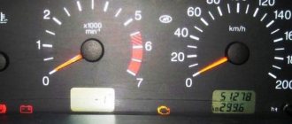
Occasionally, error No. 53 is stored in the ECU memory, the status is accumulated. Visible only by entry in BC.
Symptom No. 2
The error appears more and more often. After starting the engine, the error lamp may light up, but this does not affect the operation of the car in any way. Error 53 is still present and has accumulated status.
Symptom No. 3
The car takes a little longer to start. Those. You have to turn the starter longer, literally 1-2 turns. After startup, error No. 53 is consistently recorded in the ECU. Over time, the symptom progresses.
Symptom No. 4
The car may not start at some point. After an unsuccessful start, error No. 53 is still accumulated in the ECU memory. The symptom also progresses over time.
Manufacturer
Engine 4216 is produced by the Ulyanovsk Motor Plant. Nowadays this oldest Russian plant is part of the GAZ Group holding company. UMP traces its history back to 1941. It was then, at the very beginning of the Second World War, that the capacities of the Moscow Automobile Plant named after. Stalin. The first vehicle produced by the company at the new location was the ZIS-5. After some time, the plant was renamed UlZIS.
In September 1944, the Ulyanovsk Small Engine Plant was separated from the enterprise. In the early 50s, its designers designed the first model of an air-cooled UD engine. In 1953, the company began producing Zif-5 outboard motors. Later, the plant produced a more advanced model “Veterok” for a long time.
In 1968, the Ulyanovsk Small Engine Plant was renamed UMZ. The company began assembling full-fledged automobile engines. The first UMZ engine rolled off the plant's assembly line in 1969. The company began producing gas-gasoline engines intended for commercial vehicles in 2010.
Determining crankshaft sensor malfunction
If the engine stops starting, you need to check for spark and power to the injectors. Remove the high-voltage wire from the spark plug and bring it to the engine, and then turn the starter. The absence of a spark indirectly indicates a malfunction of the crankshaft sensor. But you need to be careful, if there is still a spark, a strong discharge of current to the ground of the car can cause failure of the electronic engine control unit.
The pulley must sit tightly on the toe of the crankshaft, and if the key breaks or the ratchet unwinds, the pulley dangles, the signal from the crankshaft sensor is not correct, and the ECU supplies a spark and power to the injectors out of step.
Major breakdowns
As already mentioned, most often in UMZ-4216 engines the manifold breaks or the sensors fail. Another common problem that GAZelle car owners have to deal with is engine overheating. The temperature of the UMZ-4216 engine often increases when the speed decreases. If the car suddenly gets stuck in a traffic jam, its engine will almost completely overheat. Very often, the clutch for turning on the radiator fan starts to work incorrectly on these units.
Experienced drivers, in order to avoid overheating of the UMZ-4216 engine, advise:
- Replace the standard radiator with a copper one. This metal conducts heat very well. And, therefore, the liquid will cool better.
- Instead of antifreeze, pour high-quality imported or domestic antifreeze into the engine.
You can also combat overheating of the UMZ-4216 engine by manually turning on the fan drive from the cab. The “original” fan of the model with a problematic electromagnetic clutch should be replaced with a model with a large number of blades and a thermal switch.
How to check the crankshaft sensor yourself.
To do this, you need to remove the sensor from the engine and conduct a visual inspection; there should be no dents or cracks on it. Then you need to check the sensor winding for resistance by connecting a multimeter to the crankshaft sensor terminals.
Then quickly bring a metal object to the crankshaft sensor core; if it is working properly, you will see voltage surges on the device.
Water pump
The unit determines the flow, functionality and technical condition of the vehicle. To protect internal working cavities, special seals are traditionally used
To prevent breakdowns, it is important to use a lubricant, which can be used to pump in lubricant.
The water pump must have a sealed housing, and nothing should leak through the special drainage hole. Otherwise, the seals will need to be changed in the near future. The tightness of the water pump, like other units, is important for the correct use of the equipment.
crankshaft sensor UMZ 4216 — search on DRIVE2
Hello guys, I'm boiling, I'm tired of changing sensors
phases... In short, due to the low cost, I always bought
sensors
, to be honest, a rare g...o. Over the past 3 months I have changed 5 pieces.
Crankshaft position sensor GAZelle Business
Yesterday evening I started having problems starting. The warmed up engine started on the second or third attempt. There were no longer any options for repairs at 17:00 outside the city, so there was nothing left to do but finish the work and, if possible, move towards the house.
Sensor
The crankshaft
position is flooded again! It's like a curse! Once even after washing
The ECU reports " sensor
crankshaft
position » And how many times did I get up in the spring or
I once went to Umz
so. So there, as if a drop gets on the spark plug caps, that’s it.
P0336 Crankshaft Position Sensor Error
Symptom of a faulty crankshaft sensor
Repair of UMP – 4216…
Sigurdja › Blog › Repair of UMP
–
4216
… Sigurdja last online 2 weeks ago.
the sensor was installed in the upper radiator hose
turn on the fan and set
the sensor
to a temperature of 97°-82°. Connected.
Injecting 417th. (Part 2) - GAZ 21, 2.4 l., 1967
Overhaul of UMZ 4216
Hooray! STARTED... and less than a year has passed! — KIA Sportage, 2.0 l., 2001.
Sensor
synchronization 35.3847 is designed to generate an electrical signal when the angular position of a special toothed disk mounted on the
engine
crankshaft .
The sensor
is used as part of a comprehensive engine control system.
How to check the Crankshaft Position Sensor (CPS)
Sensor
crankshaft position
- all about
the crankshaft
sensor It is very difficult to imagine a modern miracle of engineering - a car without an abundance of electronic systems.
Camshaft and crankshaft sensors ZMZ 406. - Community.
Good day everyone! If with sensors
temperatures and their manufacturers, everything is clear (except for the recommended 405226, there is nothing special to take), then with the above
sensors
I don’t know what to choose, the topic is not discussed, so I turn to the community.
Gazelle error 053. crankshaft position sensor malfunction
Good afternoon everyone. Tell me who is in the subject. Such an incident happened for two days in a row, I drove a gazelle 406 engine and had no complaints about the work. But on the third it didn’t start. When you turn the engine it catches periodically but refuses to work.
Report after updating the UMZ 4216 - GAZ software.
DPKV from Gazelle - Great Wall Hover, 2.0 l., 2014
Measure seven times (crankshaft position sensor) - UAZ 3160.
Ignition system UMZ 4216
The electronic control unit receives reference signals from sensors
crankshaft position and
phases.
The UMZ
4216
ignition system is part of the engine control system and consists of an ignition coil, high-voltage wires, etc.
GAZ Gazelle UMZ 4216
Colleague! Health to you and everything connected with you. I recently rode a Gazelle 3302 farmer 4x4 with a UMZ
4216
injector Euro 3 2012.
Question about the sensor on UMZ 4213; 4216 - Community "UAZ drivers".
I didn’t like UMZ
4216
or
UMZ
motor on
sensor
When will I get married ZMZ-40200M and ZMZ- 4216
and they will install it on the Volga to scribble over this problem.
In the 402, the crankshaft
do not fall out below the belly and therefore the block is more rigid.
Cooling system features
Maintenance and adjustment of cooling system units are mandatory taking into account the technical parameters of KamAZ. The engine operates normally if the temperature conditions are maintained. Overheating and hypothermia are potentially dangerous. Incorrect temperature conditions reduce the service life of the units used. At the wrong temperature, the use of fuel is impaired, as it does not evaporate, ignite and burn well, so the engine runs with less power and consumes more fuel.
The installed KamAZ fan sensor helps in monitoring the characteristics and maintaining them under different weather conditions.

