Rear wheel brake system
The rear wheel brake mechanism is unified in most parts with the rear brake of the VAZ-2101, VAZ-2102 models and their modifications. The exception is the brake shield 12 (Fig. 203) and the wheel cylinder 10, which have an original design. The wheel cylinder contains a device for automatically adjusting the gap between the shoes and the drum. Its main element is a split thrust ring 9 (Fig. 204), installed on the piston 4 between the shoulder of the thrust screw 10 and two nuts 8 with a gap of 1.25-1.65 mm. The thrust rings are installed in the cylinder with an interference fit that provides a shear force of the rings along the cylinder mirror of at least 35 kgf, which exceeds the force on the piston from tension springs 11 and 1 (see Fig. 203) of the brake pads.
With an optimal gap between the pads and the drum, when braking, the pads move apart until a gap of 1.25-1.65 mm is selected between the screw shoulder and the thrust ring shoulder. The specified gap allows the pads to move to create maximum braking torque on the rear wheels.
When the linings are worn, the gap of 1.25-1.65 mm is completely eliminated, the shoulder on the thrust screw 10 (see Fig. 204) is pressed against the shoulder of the ring 9, as a result of which the thrust ring moves after the piston by the amount of wear. When the braking stops, the pistons are moved by the force of the tension springs until the crackers stop against the shoulder of the thrust rings. This maintains optimal clearance in the brake mechanism.
Braking system of modern cars
The general braking scheme on modern cars suggests the presence of three main types:
The working vehicle performs the functions of reducing the speed of the vehicle or stopping it.
The spare vehicle is intended to prevent malfunction or failure of the working system.
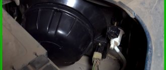
The parking vehicle performs the functions of holding the vehicle stationary in special conditions and in parking mode. The VAZ-2107 implements a working and parking vehicle in a “pure” form.
In a modern car, braking can be performed not only by the vehicle itself, but also by the engine, electric or hydraulic transmission brake. In addition, additional systems (or devices) are often implemented that increase the productivity of braking functions:
- anti-lock braking system (the notorious ABS);
- electric brake force distribution (or EBD);
- electrical stabilization system (ESP), etc.
The described devices and systems lead to a significant increase in the cost of the vehicle, and the VAZ-2107 brake system diagram does not provide for them.
However, domestic cars have recently begun to provide similar capabilities.
Drum type brake with self-aligning pads
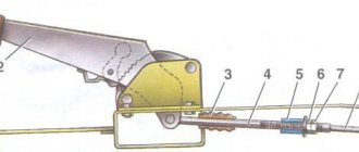
Brake pads 5 and 2 (see Fig. 203), wheel cylinder 10 and other parts of the brake mechanism are mounted on a shield 12, which is attached to the flange of the rear axle beam. The bottom of the pads rests on plate 3, which is included in the package of plates riveted to the brake shield. The upper part of the pads fits into the grooves of the wheel cylinder piston stops. The pads are held against axial displacement by springs installed on the racks 6. The lever 7 for the manual drive of the pads is hingedly connected to the rear brake pad, with pin 9. Its edge fits into the groove of the expansion bar 8, into the opposite groove of which the front block 2 fits. The blocks are pulled together by springs 1 and 11.
Source
Summarize
The brake system of the VAZ-2107, like any other car, is an important component of an integral vehicle control system that ensures traffic safety.
Diagnostics and timely repair of vehicles is a vital necessity.
Let's first take a look at what brake systems are available in this car model. There are only two of them:
A working vehicle is used to allow the vehicle to reduce speed and stop. The parking lock fixes the vehicle in a stationary state when the driver needs it. They do not depend on each other, but setting off on a journey knowing that one of them is faulty is strictly prohibited. Naturally, the front and rear brakes should also always be replaced in a timely manner.
Rear brake system
Rear wheel brake
| 1 – Wheel cylinder; 2 – upper tension spring of the pads; 3 – pad lining; 4 – brake shield; 5 – inner plate; 6 – rear cable sheath; 7 – lower tension spring of the pads; 8 – front brake pad; 9 – pad support plate; 10 – rivets; 11 – oil deflector; | 12 – pad guide plate; 13 – rear parking brake cable; 14 – rear cable spring; 15 – rear cable end; 16 – rear brake pad; 17 – block support post; 18 – lever for manual drive of the pads; 19 – rubber cushions; 20 – pad spacer; 21 – finger of the lever of the manual drive of the pads |
| 1 – block stop; 2 – protective cap; 3 – cylinder body; 4 – piston; 5 – seal; 6 – support cup; | 7 – spring; 8 – crackers; 9 – thrust ring; 10 – thrust screw; 11 – fitting; A – slot on the thrust ring |
Wheel cylinder parts
| 1 – piston assembly; 2 – cylinder body; 3 – thrust screw; 4 – thrust ring; 5 – crackers; | 6 – spring; 7 – support cup; 8 – seal; 9 – piston; 10 – protective cap |
The rear wheel brake is drum type with self-aligning pads. Brake pads 8 (see figure Rear wheel brake mechanism) with linings, Wheel cylinder 1 and other parts are mounted on the brake shield 4, which is attached to the flange of the rear axle beam.
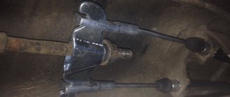
Adjusting the handbrake yourself
If you promptly ask yourself the question of how to tighten the handbrake on a VAZ-2107, and do all the work correctly, you will be able to avoid a number of unpleasant situations. Securely locked wheels will prevent the car from rolling away while parked. In addition, a properly functioning hand brake system makes it much easier to move the car away if you are on a steep road. Therefore, if the handbrake on a VAZ does not work effectively enough, read the instructions for adjusting it.
Timely tightening of the handbrake on the VAZ-2107 will allow you to avoid unpleasant situations
Before pulling the handbrake on the VAZ-2107, make sure that the brake pads of the rear wheels are in good technical condition. And also check the condition of the cable itself - perhaps it is too stretched or worn out and a regular tightening will not solve the problem. And also check the operation of the handbrake drive. If all parts are in good condition, prepare two “13” wrenches and pliers and begin adjustment, guided by the sequence of actions described below:
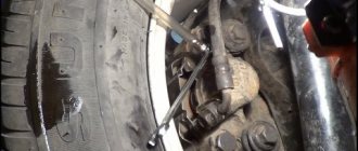
- The VAZ-2107 hand brake is adjusted under the bottom of the car, so it must be installed above the inspection hole or the rear of the car must be raised using a jack.
- Set the parking brake lever to the applied position by tightening it 5–6 clicks.
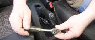
- After this, while under the car, remove all dirt from the adjusting rod and nuts. After cleaning, hold the adjusting nut with one wrench and loosen the lock nut.
- Next, by tightening the adjusting nut, you need to tighten the handbrake cable until the rear wheels lock. During the process, the adjusting rod should be held with pliers so that it does not rotate.
- After the required degree of cable tension has been set, tighten the nut a few more turns - this is necessary to reduce the free play of the lever.
- Now check if the wheels actually brake, and if everything is fine, you can tighten the lock nut.
If the handbrake tension is adjusted correctly, the brake pads will hold the car on a 25% slope.
Upon completion of the work, it would be useful to lubricate the threaded connections, for example, with lithol - this will make the adjustment process easier the next time. So, now you have learned how to tighten the handbrake on a VAZ-2107 car, but you still need to check the system in action. To do this, find a road section with a 25% slope (or a suitable overpass) and after stopping, pull the handbrake lever 2-4 clicks. If the tension is adjusted correctly, the brake pads will hold the car in place.
REAR BRAKES
DEVICE FEATURES
The rear wheel brake mechanism is drum type, with self-aligning pads. Brake pads 8 (Fig. 2) with linings, wheel cylinder 1 and other parts are mounted on the brake shield 4, which is attached to the flange of the rear axle beam.
Adjustment of the gap between the shoes and the drum is ensured automatically using a device located in the wheel cylinder 4. Its main element is a split thrust ring 9 (Fig. 3), installed on the piston 4 between the shoulder of the thrust screw 10 and two cotters 8 with a gap of 1.25 -1.65 mm. The thrust rings are installed in the cylinder with an interference fit that provides a shear force of the rings along the cylinder mirror of at least 35 kgf, which exceeds the force on the piston from the tension springs of the brake pads.
With an optimal gap between the pads and the drum, when braking, the pads move apart until a gap of 1.25-1.65 mm is selected between the screw shoulder and the thrust ring shoulder. The specified gap allows the pads to move to create maximum braking torque.
When the linings wear, the gap of 1.25-1.65 mm is completely eliminated, the shoulder on the thrust screw 10 is pressed against the shoulder of the ring 9, as a result of which the thrust ring moves along with the piston by the amount of wear. With the cessation of braking, the force of the tension springs moves the pistons until the crackers stop against the shoulder of the thrust rings. This maintains optimal clearance in the brake mechanism.
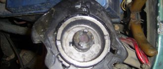
REMOVAL AND DISASSEMBLY
Lift the rear of the car and remove the wheel.
Take measures to prevent fluid from leaking from the reservoir.
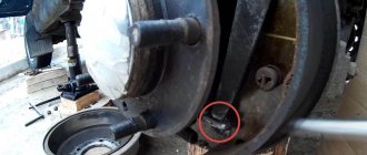
Rice. 1. Rear wheel brake drum : 1 - bolts securing the drum to the axle shaft; 2 - threaded holes for installing bolts 1 when removing the drum
Remove the brake drum by unscrewing the mounting bolts 1 (Fig. 1). Insert these bolts into technological holes 2 and tighten until the drum separates.
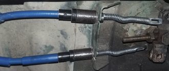
Disconnect the end of the cable from lever 18 (Fig. 2) of the manual shoe drive, remove the cotter pin, press pin 21 and remove the lever.
Rice. 2. Rear wheel brake mechanism : 1 - wheel cylinder; 2 — upper tension spring of the pads; 3 — pad lining; 4 — brake shield; 5 — inner plate; 6 — rear cable sheath; 7 — lower tension spring of the pads; 8 — front brake pad; 9 — pad support plate; 10 - rivets; 11 — oil deflector; 12 — pad guide plate; 13 — rear parking brake cable; 14 — rear cable spring; 15 — rear cable end; 6 — rear brake pad; 17 — block support post; 18 — lever for manual drive of the pads; 19 — rubber cushions; 20 — pad spacer; 21 — finger of the lever of the manual drive of the pads
Use pliers to disconnect the upper 2 and lower 7 tension springs.
Basic faults
The most common malfunction of the VAZ 2107 brake system is the ineffectiveness of the braking itself. The driver himself can notice this malfunction by eye:
- when braking, the braking distance increases;
- The braking process itself takes longer than before.
This malfunction can be caused by a number of breakdowns:
- there are air pockets in the system;
- leakage of brake fluid;
- severe wear of the pads;
- cylinder failure.
For the VAZ 2107, the braking distance is determined: at a speed of 40 km/h on a flat and dry road, the braking distance should not exceed 12.2 meters until the car comes to a complete stop. If the path length is higher, then it is necessary to diagnose the performance of the brake system.
In addition to ineffective braking, other malfunctions may also occur:
- strong grinding noise (noise) when squeezing the brake pedal;
- the car swerves to the sides when slowing down;
- softened brake pedal lowered;
- vibrations and jerking when pressing the pedal.