They brought the specified charger for repair; the stated fault, translated into technical language, was a very high charge current, which is not regulated. Let's look at the diagram, of course:
Again we see an absurdly complicated design. First thought: check VT1. The collector-emitter junction is broken! The transistor is of the KT209L type, you can’t find those anymore, and there’s no need. I install the KT502E - everything, the charger is working, the charging current is adjustable, the automatic and manual modes are working.
No, I don’t encourage everyone to take up soldering irons and start repairing industrial electronics. But such and such an elementary malfunction could be resolved on your own. Or ask a friend/fellow electronics engineer. After all, what is the alternative: either repair yours with little effort (and little money), or buy a new one in the store. Will this new one be more reliable than what was released before?
see also
Comments 8
Well, my grandmother said it in two), I myself use a device made in the USSR, I think it will also be useful for my grandchildren.
How can I reduce the voltage of this charger? at 2 Amps 17.2 volts. (too much, the battery starts to boil)
You mean tension, am I correct? In what mode (manual, automatic, battery connected or not) and with what voltmeter was it measured?
Yes, tension. This device has short circuit protection, so measurements were made with the battery connected. I measured it with a tester and a volt-ammeter with an alli. The mode doesn’t matter whether it’s manual or automatic, it still raises the voltage to 17 volts. Yesterday I gave the memory to the master for inspection. His first assumption was the following: that the charger was from Soviet times and was designed for 220 volts, today in a household electrical network it is 235-240 volts. Perhaps because of this, the voltage on the secondary winding has increased.
If the device is working properly, then the RU resistor is responsible for limiting the output voltage in charging mode.
Yes, tension. This device has short circuit protection, so measurements were made with the battery connected. I measured it with a tester and a volt-ammeter with an alli. The mode doesn’t matter whether it’s manual or automatic, it still raises the voltage to 17 volts. Yesterday I gave the memory to the master for inspection. His first assumption was the following: that the charger was from Soviet times and was designed for 220 volts, today in a household electrical network it is 235-240 volts. Perhaps because of this, the voltage on the secondary winding has increased.
Good afternoon. I have been recharging batteries with this charger all my life and yesterday I accidentally measured the output voltage without connecting the battery, i.e. The idle voltage was also about 17 Volts, and when the battery was connected at a current of 1.5 A, the voltage was 13.4-13.8 Volts. The question is how to correctly measure voltage with or without a battery connected?
Recommendations
- After storing the device in the cold or after transporting it in winter conditions, keep it at room temperature for 4 hours before plugging it in.
- The difference in the density of the electrolyte of a fully charged battery in each battery should not exceed 0.01 g/cm3. If the difference exceeds the specified value, then the electrolyte density must be adjusted.
- Before disconnecting the battery, you must first unplug the device.
- If there is no indication at all on the front panel of the device, you need to check the fuse located under the cover (12). To do this, unscrew one screw and remove the cover.
GENERAL INFORMATION
The charger UZS-P-6/12-6.3 UHL 3.1 “Rassvet-2”
is intended for charging and recharging batteries of passenger cars and motorcycles.
The Rassvet-2 charger produces a charge with a stabilized current in any of two modes:
In manual mode - charge 6 V and 12 V lead-acid batteries. In automatic mode - charge and recharge 12 V lead-acid batteries.
The Rassvet-2 charger has electronic protection against short circuits at its output and incorrect (polarity) connection to the battery terminals.
In addition, “Rassvet-2” allows you to determine the degree of charge of the battery, the serviceability of the battery, and the polarity of the battery terminals if there are no markings on them.
The charger UZ-12-6 UHL3.1 “Rassvet-2M”
is designed for charging and recharging serviceable acid batteries of passenger cars with a rated voltage of 12V and a capacity of 40-75 Ah.
The device charges rechargeable batteries in a mode close to the “constant voltage” mode, which ensures their safety and durability. The Rassvet-2M charger has short circuit protection for electrical circuits.
Operating modes
The Rassvet-2 charger has two operating modes switchable by pressing a button on the front panel: Manual (RUCH) and Automatic (AVT). Both modes are intended for charging with stabilized current exclusively for lead-acid (ordinary) batteries:
- Manual
- charge 6 V and 12 V lead-acid batteries. - Automatic
– charge and recharge 12 V lead-acid batteries
The device charges batteries in a mode close to the “constant voltage” mode, which ensures their safety and durability. The device has electronic protection of electrical circuits against short circuits at its output and incorrect (polarity) connection to the battery terminals.
ORDER OF USE OF THE DAWN-2 charger
5.1.3.
A fuse is installed under cover 12. Cover 12 is attached to the body with 1 screw. To provide access to the fuse when replacing it, you must remove cover 12. Note. Due to the continuous improvement of the ultrasonic design, there may be minor differences in the product from the one described above.
5.2. Functionality check:
5.2.1 To check the operation of the ultrasonics, it is necessary to: 1) set handle 5 to the extreme left position; 2) press button 3—manual operating mode. 3) connect the power cord 9 to the network, and the network indicator 6 should light up; 4) connect to terminals AND a 12 V car lamp with a power of 21 W (21 cd); 5) press the “Control” button 4 and, without releasing it, turn knob 5 clockwise, while the lamp and current indicator 7 should light up. When button 3 is pressed—automatic operating mode—the lamp will glow pulsatingly.
6. PREPARATION AND OPERATION PROCEDURE
Charger ";Rassvet-2";
Angel Kostov, Bulgaria. Shumen (at) inbox.ruI present to your attention the circuit diagram of the Rassvet-2 charger, which I removed from the original charger. I made 2 chargers using this scheme and they work exactly like the original one.
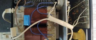
Structurally, the charger (charger) is made in the form of a separate unit, closed by a housing from exposure to bad weather and moisture. A power transformer, powerful control thyristors on radiators, a charge current stabilization board and thyristor control board, terminals for connecting the battery being charged with wires with a cross-section of at least 2.5 mm2 (“+” on the case) and a power switch are attached to the base of the case. . 1.
Rice. 1.
The control and stabilization board is installed on the front panel of the case in such a way that the buttons for switching the charging mode - “Manual - automatic” and switching on the charge fall into a specially cut groove and are easily switched. A manual charge current regulator (Rp) is also located on the front panel. The control board diagram is shown in Fig. 2.
Rice. 2.
Specification of components (in Bulgarian, but in my opinion everything is clear and does not require translation).
- Transistori:
- Diodi:
- Resistance /resistor/:
- Capacitors
a/ VT1 and VT10 = KT209 or VS557 b/ VT3 and VT7 = KT315D c/ VT2, VT4, VT5, VT6, VT8 and VT9 = KT361D or VS557
a/ VD13 = KC147 /tsener/ b/ VD19 = D816D /tsener/ c/ VD5 = LED, Russian, /cherven/ d/ VD6 = LED, Russian, /green/ d/ VS1 and VS2 = KU202L e/ VD1-VD4 , VD8, VD9, VD12, VD15-VD18 = D226V or 1N4003
a/ Rp /potentiometer installed/ = 4.7k b/ Ra /trimer-potentiometer for silat on charging current, Imax = 6.3 A/ = 3.3k c/ Ru /trimer-potentiometer for dolnata limit per discharge with automatic. cycle 13.9V/ = 3.3k g/ resistors 1W: R4 = 150 ohm, 1W; R8 = 300ohm, 1W; R12 = 1k, 1W
d/ Resistance 0.25W:
R1, R3, R21, R23 = 3.6k; R2 = 510 ohm; R5, R10 = 20k; R6, R7, R13, R24 = 1k; R11 = 75k; R14 = 3k; R18, R19, R25 = 10k; R22 = 9.1k; R26 = 300ohm R27 = 51k;
C1, C2, C3 = 0.1 µF, 160 V C4 = 20 µF, 16 V; C5, C6 = 100 µF, 25 V; C7 = 20 µF, 50 V
The appearance of the printed circuit board is shown in Fig.
3. Fig. 3.
And the view of the board from the wiring side is in Fig. 4.
Rice. 4.
Any power of 180-250 W can be used as a power transformer, delivering an alternating voltage of ~16...22 V and rated for a current of 6...10 A.
In conclusion, I would like to say a few words about the high reliability of the circuit, since thyristors operating in switching mode are used as powerful control elements.
Approximate norms for adjusting electrolyte density, g/cm 3
| Rated supply voltage, V |
| frequency Hz |
| Rated voltage of batteries being charged, V |
| Rated current value, A |
| Current adjustment is smooth, in the range, A |
| Operating temperature range |
| Overall dimensions, mm |
| Weight, kg |
| Electricity consumption, kWh, no more |
To the left of the bold line: after removing the indicated volume of electrolyte, it is necessary to add the same amount of electrolyte with a density of 1.40 g/cm 3 .
To the right of the bold line: after removing the specified volume of electrolyte, you must add the same amount of distilled water.
6.3.2. After the battery has finished charging, disconnect the power cord 9 from the network and the load cables from the battery.
6.4. Charging and recharging a 12 V battery in automatic mode:
6.4.1. Install handle 5 according to the instructions in the previous section. 6.4.2. In automatic mode, charging current is supplied to the battery cyclically. The duration of the current cycle is 5..35 s. During the flow of current, indicator 7 lights up. Between current cycles there is a dead pause, during which indicator 7 does not light up. As the battery charges, the pause increases from 0.5. 1s, with a battery discharged to 50% - up to 0.5. 2 minutes, and 6 more at the end of its charge (battery charge 95.100%). 6.4.3. If after charging for 0.5. 2 hours (depending on the state of charge of the battery) the pause does not increase, this is a sign of a faulty battery
Brief instructions
Charge a 12 V battery in automatic mode:
In order to charge a car battery in automatic mode, you need to connect the charger terminal to the battery terminals and only then plug the charger into the outlet.
Then the initial charging current is set (1/10 of the battery capacity), after which you need to press the “AVT” button. In automatic mode, charging current is supplied to the battery cyclically. The duration of the current cycle is from 5 to 35 seconds, after which a pause begins during which no current is supplied. While current is flowing, the corresponding current indicator lights up; during a pause, it does not. As the battery charges, the pause increases from 0.5 - 1 second, with the battery discharged to 50% - to 0.5 - 2 minutes, and 6 more at the end of its charge (battery charge is 95...100%).
If after charging for 0.5 - 2 hours (depending on the state of charge of the battery), the pause does not increase, then this is a sign of a faulty battery.
Charge 6 and 12 volt batteries manually:
In manual mode, you need to gradually reduce the current yourself (the correct cycle is 4-5A - 10 minutes, 3A - 30 minutes, 2A - 2-3 hours, 1A 1 hour for a total of 4-5 hours with a completely discharged battery).
If there is current, the corresponding indicator should light up. The voltage is set automatically and will increase as the battery charges, keeping the current constant. At the same time, the voltage of serviceable lead-acid 6V batteries increases at the end of their charge to 8.1V, 12V - to 16.2V.
A sign of the end of the battery charge is abundant gas evolution, constant voltage and electrolyte density in all batteries for two hours.
The “Control” button serves only to check the functionality of the charger itself, and has nothing to do with the charging process.
Checking the functionality of the memory:
To check the functionality of the device you must:
- set the “Current” knob to the extreme left position - 0;
- press the “MANUAL” button - manual operation mode.
- connect the power cord to the network, the network indicator should light up;
- connect a 12 volt car lamp with a power of 21 W (21 cd) to the output terminals;
- press the “Control” button and, without releasing it, turn the current adjustment knob clockwise, while the lamp and current indicator should light up. When the "MANUAL" button is pressed - automatic operating mode - the lamp glow will pulsate.