A charger is an absolutely necessary device for any car owner. Chargers allow you to carry out battery maintenance - from renewing the energy reserve to desulfating the battery (depending on the version), and if you have a starting charger, you can start the car from it. Like any electronic components, these devices sometimes fail. Under certain conditions, you can repair a faulty car battery charger yourself.
The most common breakdowns and their diagnosis
The most obvious sign of a breakdown is that when turned on and connected to the battery, the charger shows no signs of life:
- indicators do not light up;
- pointer voltmeters (if available) do not indicate the output voltage level;
- the device does not respond to manipulations with controls (pressing buttons, clicking toggle switches, etc.).
In many cases, the problem lies in the power cord or fuses. Many chargers have fuses inside the case. To get to them, you need to remove the cover. Sometimes they may not be there at all, despite the fact that they are indicated on the diagram.
No fuses were found inside the Kedr device.
Many chargers turn on only when a battery charged to at least 10 volts is connected to the terminals.
If the device responds to being connected to the network, but when the battery is connected, neither voltage nor current are displayed, there is reason to assume that the power part has failed (although the problem may be in the control circuit). It should be noted that primary diagnostics is more applicable to memory devices built according to a linear circuit. For pulse generators, the same external manifestation of a problem can be caused by completely different faults, so it is better to immediately begin disassembling and checking the circuit.
Principle of operation
The operation of the charger is based on reducing the voltage and converting alternating current to direct current. For this purpose, the circuit contains a step-down transformer and a diode bridge. The charging voltage should be 5-10% higher than the nominal value of this parameter for the battery, and the charging current should be about 10% of its capacity. Sometimes the phone is recharged from the car's DC battery. In this case, rectification (conversion from variable to constant) is not necessary.
DIY Repair Tips
Troubleshooting and repairing a charger is a creative process; the fault can lie in anything, so it is impossible to provide step-by-step repair instructions. But we can sort out the general principles.
To diagnose and repair a memory, you need to understand its structure. Chargers are built according to two schemes:
- linear;
- pulsed.
Each option has its own advantages and disadvantages.
Linear memory structure.
Linear type chargers are built relatively simply:
- 220 volts goes to the power transformer, which reduces the mains voltage;
- the secondary voltage is rectified by a controlled rectifier (usually based on thyristors, but there are also powerful transistors);
- the control circuit specifies the operating modes of the memory (performed both on discrete elements and on microcontrollers;
- measuring instruments indicating current and voltage (there may not be a voltmeter - current is more important).
As a rule, there is no output filter in linear chargers - this is not needed to charge the battery.
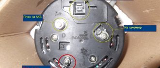
Scheme of the Kedr-auto linear charger.
The Kedr-auto charging and recharging device was built on a similar principle. When plugged in, you should hear a low-frequency rumble and feel a slight vibration. If this is not the case, you need to check the voltage of 220 VAC at points 1 and 2. If it is not there, you need to look in the power cord and fuses. If there is voltage, there is a high probability of failure of the power transformer. If everything is in order, the presence of low alternating voltage is checked at points 3 and 4. If it is present, then the diagnosis of the power transformer is completed.
Next, the power part is checked. The thyristor is tested by a tester in diode continuity mode . In the normal state, the resistance in both directions should be high - the device is locked. But if you touch the anode and the control electrode simultaneously with the positive probe of the tester, the thyristor will open and the multimeter will show some resistance. This means the valve is working properly.
Checking the serviceability of the thyristor.
If the power transformer and key elements are working properly, then the problem is in the control circuit. Different charger models use different designs of such devices, so it is impossible to give general recommendations. In each specific case you need to figure it out yourself. If the circuit is assembled using discrete elements, there is a chance of success. If the charger is controlled by a microcontroller, it is unlikely that it will be possible to repair the charger. Replacing the microcircuit is easy, but finding the firmware is difficult.
If a charger made using a pulse circuit does not work, then in addition to the devices, a certain level of knowledge and qualifications will be required - such devices are much more complex.
Structure of a pulse charger.
In such a device the mains voltage is:
- passes through a surge protector;
- straightened and filtered;
- using an inverter controlled from a separate circuit, pulses with an amplitude of about 300 volts and a frequency of several kilohertz/tens of kilohertz are cut;
- pulses are transformed by a step-down transformer;
- then the reduced voltage is rectified and filtered (the filter serves here not only to smooth out the voltage, but also to eliminate some of the high-amplitude surges - the battery does not like them);
- through feedback circuits and a control circuit, the operating mode is set (current stabilization, voltage stabilization, training cycle, etc.).
The basic principles of troubleshooting can be considered using the example of the ZU-3000 charger.
Scheme of the pulse charger "ASTRO" ZU-3000.
First of all, you need to check the alternating voltage at the input of the diode bridge (after resistors R1 and R2). There should be 220 VAC. If not, you need to check sequentially:
- fuse serviceability;
- power cord and plug;
- input filter elements (primarily the thermistor).
If everything is in order, then the voltage at the bridge output is checked (on capacitors C2, C3, C4). there should be about 300 volts DC. If not, check the serviceability of the bridge diodes VD1-VD4, then capacitors C2, C3, C4. If everything is OK there, you need to use an oscilloscope to verify the presence of pulses at output D of assembly DA1. If they are not there, there is reason to suspect a failure of the power transformer or TOP225YN PWM controller. If everything is fine here, the secondary circuits are checked - rectifier, filter, feedback. If the AtTiny-26 controller is faulty, the chances of successfully repairing the device are slim.
Checking the power supply
How to check amps with a multimeter on a power supply? This is also done to break with the obligatory application of load. The principle itself differs little from checking other sources. It is only necessary to note that power supplies have quite a lot of power, so measurements should be carried out quickly, avoiding heating the wires of the multimeter probes.
As we can see, a multimeter can be very useful in everyday life and is in demand in completely different areas, so obtaining the most minimal knowledge on its use will not be superfluous at all.
A properly charged battery is an indispensable condition for a comfortable ride. During the cold season, it is especially important that the battery ensures reliable starting of the car engine.
Modern cars, especially luxury cars, have a battery charging control unit that monitors the main parameters of the process. There are no such devices in budget category vehicles. Experienced drivers perform this task independently. Let's look at how to have the most complete control over the battery charging process.
Serviceability test
It was mentioned above that many chargers do not turn on if there is no battery connected. To test the charger after repair, if you are not completely confident in the serviceability of the device, it is advisable to take a battery that you don’t mind if it has lost capacity, etc. Having connected such a battery to the charger, you need to check the voltage level at the charger terminals. It should be approximately 14-15 volts. If it is significantly more or less, or the level is unstable, the charger is faulty.
Checking the memory under load.
In this case, it is necessary to control the current strength (this can be done using a standard ammeter). It should be within 0.1 of the battery capacity (if the battery is not very discharged). The accuracy of the data of the built-in device can be checked with an external ammeter (for example, a multimeter).
Battery is low
As practice shows, the critical voltage level of a twelve-volt battery is a voltage of 10.8 volts. This type of discharge is called deep. Such a discharge is detrimental to the battery, it significantly reduces the service life of the car.
The table shown above shows how the degree of charge is continuously related to the density of the electrolyte. The battery charge can be checked not only by the voltage at the terminals. You can also check the density of the electrolyte. The density of a fully charged battery should be between 1.27 and 1.29 g/kb.cm. The density of the electrolyte can be measured with a simple device - a hydrometer.
Is it worth repairing it yourself and where can I get it repaired?
The charger is a rather complex device, and it is not always possible to visually detect a defect. In addition, even if a charred element is found, the cause may be in another component. Replacing a burnt part will only lead to a repeat of the accident. Therefore, for self-repair, you will need at least knowledge of electronics and a general understanding of the principles of constructing chargers. You also need a minimum equipment set - a multimeter, and in some cases an oscilloscope. If any of these factors are missing, it is better not to undertake repairs. There is also little point in repairing chargers where a fault is found in the winding elements (transformers, chokes) if there is no donor device. It will not be possible to rewind them “on the knee” with factory quality, especially in pulse-type devices.
For clarity, we recommend thematic videos.
For repairs, you can contact specialists. And it is best if it is possible to take or send the faulty charger to an official service center . If this is not possible, you can look for a specialist on the Internet - on message boards or specialized forums. You can also contact your friends or garage neighbors. But if the memory device falls into the hands of self-taught people, the risk of poor-quality repairs increases many times over.
Finding the cause of the memory malfunction
Before looking for the cause of the malfunction, you need to know what type of device your device is:
- Transformer - voluminous and heavy, but easy to repair and maintain.
- Pulse is a modern compact equipment characterized by increased operational reliability. Not everyone can repair it at home; knowledge in the field of electronics is required.
How to check the charger for a car battery
The battery is connected to the charger, but for some reason it does not take charge from it? In this situation, you should make sure that the charging equipment is indeed faulty. This can be done in several ways:
- Use a multimeter to measure the voltage produced by the charger. If this value turns out to be less than 13 V or it is unstable - it changes abruptly, then we can safely conclude that repair is required.
- Measure the current strength by connecting a multimeter directly between the battery terminal and the “crocodiles” of the charger. On a working charger, the current characteristic value should correspond to 10% of the capacitance value indicated on the battery label.
Disassembly and testing of the device
Let's look at how to independently disassemble and test a charger for a car battery, using transformer-type devices as a sample. The design of these devices is quite simple; the cause of the breakdown also often lies on the surface.
For safety reasons, be sure to unplug the charging equipment before disassembling or repairing it.
Armed with a screwdriver, carefully loosen the fastening elements: screw or bolt connections - and remove the housing cover. Now all the “internal filling” of the device is before our eyes.
We carefully inspect all wires for integrity. We pay special attention to the places of their connections with component parts. The contact between them may be disrupted due to a wire break or burnout, as well as a simple weakening of the connection.
If there is a burning smell or soot on the walls, then this is a clear sign of burnt-out transformer windings. Do not neglect a detailed inspection of plastic connecting components, which can melt and short-circuit the circuit.
If the visual inspection does not produce results, we proceed to testing and carrying out diagnostic measures to determine the ability to operate individual parts included in the operating circuit of the device.
The main causes of memory failure
Quick and high-quality elimination of damage to a memory device can be helped by good knowledge of the main reasons that can provoke its premature shortening of the “life” cycle. Knowing which of the factors could most likely cause a malfunction of the device, it is much easier to find the malfunction itself.
The most common reasons leading to a significant reduction in the service cycle of chargers are:
- improper operation;
- violation of the rules for storing the device;
- operational defect of wires;
- the resource of one of the structural elements of the circuit has been exhausted.
Charger testing
Having completed the diagnostics and eliminated the cause of the charger failure, you should make sure that it is working before you start charging the battery.
Using a multimeter that is universal in all respects, we will test the basic parameters of the device:
- Having switched the multimeter to ammeter mode, we connect it in series to the circuit, having previously set the required current value on the charger - one tenth of the capacity. The instrument readings must correspond to the set value on equipment that is in working order and ready for use.
- Now let's switch the multimeter to voltmeter mode and connect it in parallel to the terminals of the device for charging. If the malfunction was actually eliminated, then the voltage value that the equipment is capable of producing during operation will be more than 13.2 V. Otherwise, the charger is unusable.