A charger is an absolutely necessary device for any car owner. Chargers allow you to carry out battery maintenance - from renewing the energy reserve to desulfating the battery (depending on the version), and if you have a starting charger, you can start the car from it. Like any electronic components, these devices sometimes fail. Under certain conditions, you can repair a faulty car battery charger yourself.
How to repair a car battery charger
Automotive battery chargers (BACs) are available in large quantities on the consumer market. However, any of them can break down over time during use. Therefore, it will not hurt car owners to know how to carry out simple repairs of chargers for car batteries. Of course, a lot depends on the degree of damage: if it is the simplest, there are elements that you can fix yourself.
Main types of ROM
All chargers, based on the principle of operation, are divided into two types: pulse and transformer . A pulse device operates due to the presence of a pulse current converter in it. And inside the transformer charging there is a simple transformer with a rectifier, due to which the ROM weighs more and looks more bulky than a pulse one. Pulse-type devices are considered more reliable in operation, but transformer-type devices are easier to maintain and repair.
How to check the charger
If you decide to charge your car battery at home, but have doubts about your charger, this article is for you. A simple check determines the quality and serviceability of its operation.
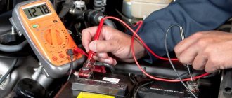
One way is to connect it to the battery and measure the voltage readings with a multimeter. The optimal U in this case is 14 V, a little higher is allowed, up to 14.4 V. If U is less than 13 V, or the multimeter detects its jumps, then there is definitely a malfunction, and it is necessary to carry out some kind of repair of the starting-charger.
If you don’t have a battery at hand, you can check the functionality of the charger with a simple electric light bulb rated for U 12 V. If the light bulb starts to light when connected to it, charging is working normally, and if the light bulb does not light up, the device should be repaired.
Details
The charger and starting device uses a power transformer from the Rubin TV. It is also possible to use a TCA-270 type transformer. Before rewinding the secondary windings (the primary windings remain unchanged), the frames are separated from the iron, all former secondary windings (up to the screen foil) are removed, and the free space is wound with copper wire with a cross-section of 1.8...2.0 mm2 in one layer (up to filling) secondary windings. As a result of rewinding, the voltage of one winding should be approximately 15 ... 17 V.
To visually monitor the charging and starting current, an ammeter with a shunt resistor is introduced into the circuit of the charging and starting device. Network switch SA1 must be designed for a maximum current of 10 A. Network switch SA2 (type TZ or P1T) allows you to select the maximum voltage on the transformer in accordance with the network voltage. The internal battery of the 6ST45 or 6ST50 brand should be enough for 3-5 simultaneous starts. Resistors in the ZPU can be used like MLT or SP, capacitors C1, C2 - KBG-MP, C3 - MBGO, C4 - K50-12, K50-6. The D160 diodes (without radiators) can be replaced with others with a permissible current of more than 50 A, the triac is of the TC type. The connection of the charger to the car battery must be done using powerful “Crocodile” clamps (for operating current up to 200 A)
It is important to use grounding in the device
We carry out simple ROM repairs with our own hands
You can try to carry out a simple repair of a car charger and, using the example of a transformer-type power supply, consider how this should be done.
Before carrying out any actions with the ROM, you must turn it off from the network. Carefully remove the cover using a screwdriver and first check the integrity of the wiring. It is quite possible that the problem is loose contacts, and then the problems can be solved yourself using a simple soldering iron.
It happens that some plastic connections between the components of the charger break or melt. In this case, you can also replace them yourself using a soldering iron and suitable available tools.
If all the wires and connections are in place, you should check all other ROM elements in turn . First of all, a multimeter checks the voltage level at the beginning of the electrical circuit, at the input. U is measured along the wire to the point where the wire connects to the transformer itself.
If U jumps or is not there at all, then it is checked:
- fuse (U should be on both sides, on one terminal and on the other, and if there are problems, the fuse must be replaced);
- wiring and plug (U is checked according to the same principle; if there are problems, one or the other is replaced);
- checking the transformer itself (measurements U, if there are any, the transformer is working, if not, you need to check the biscuit switch);
- if the switch is faulty, the output U will be absent but present at the input .
Principle of operation
In the vast majority of cases, mains-powered adapters operate using a pulse circuit. This allows you to obtain lightweight, compact, economical devices. You have to pay for this with complicated circuitry and reduced reliability compared to transformer power supplies.
Most network chargers have the same structure:
The rectifier is often made using a half-wave circuit - the power consumption of the charger is low, so this is sufficient. For the same reason, the capacity of the smoothing capacitor is small. The pulse generator is often circuitously combined with an inverter - the same transistor generates oscillations and switches the winding. But sometimes this unit is also built on a specialized microcircuit. The secondary rectifier is also usually half-wave to avoid unnecessary voltage drop across the diodes. Schottky diodes are used for the same purpose. In most cases, the indication circuits are an LED with a resistor.
Stabilization is carried out using pulse width modulation through feedback. In many schemes, an optocoupler is used to organize it. This ensures galvanic isolation of the output from the high-voltage part.
Checking the diode bridge
If you have the desire and ability to diagnose a diode bridge, you must keep in mind that diode bridges can be either monolithic or with the ability to replace one faulty diode with another. In case of malfunction, monolithic bridges are removed and replaced entirely. As for applying voltage to the bridge to check its normal operation, U is supplied to the ROM. If the bridge is working properly, no current will be lost at either the input or output. If the current does not flow at one of these stages, then you need to check each diode separately, identify the faulty one and replace it.
Malfunctions and methods for their elimination
After making sure that there is voltage in the socket for connection, you need to check the integrity of the plug and supply wires.
This can be done using the simplest tester. The next step is to check the transformer windings (both primary and secondary), and the fuse used in the circuit for protection. If the transformer is in good condition, plug it into the network and measure the voltage at the transformer output. It should be 14-14.5 Volts. If the voltage is less or the device detects changes, the device is faulty. The next step is to check the transformer winding switch and diode bridge. The latter consists of 4 diodes assembled in a certain way. In order to check the serviceability of each of them, you will have to disassemble the bridge circuit. A diode is a semiconductor that allows current to flow in only one direction. It is checked with a multimeter, changing the polarity. Possible diode malfunctions:
- breakdown (during continuity, current passes in both directions);
- break (does not ring in any direction).
If there are faulty diodes, they must be replaced with new ones. The final step is to check the conductors connected to the battery and the clamps. All faulty parts are replaced, broken conductors are repaired by soldering or twisting. After completing all repair work, you need to assemble the charger casing and perform a final test with a multimeter. The constant voltage on the wires connected to the battery should be 14-14.4 volts. If the charger is working normally, but the battery is not charging (the ammeter shows 0 amps), then the problem is in the battery. It should be checked in detail and replaced if necessary.
Checking the ammeter inside the ROM
For a more accurate diagnosis of a breakdown, if nothing was detected during previous checks, you should check the ammeter. If, when checking the voltage in the ammeter, it is absent, but when connecting its terminals to each other, U appears, it means that the ammeter is broken and it is time to repair it.
Thus, it is possible to carry out fault diagnosis and simple repair of chargers for automobile lead-acid batteries on your own. But when the battery is not charging due to a malfunction of the device, and the car enthusiast does not have the necessary skills in the field of electronics, or he was unable to repair the ROM himself, it is best to turn to specialists. As a last resort, you can try to charge the battery without a charger.
Well, home handymen may also be interested in learning how to make a load plug for a battery with their own hands.
Source
Photo gallery
Diagram of diagnosed charging equipment
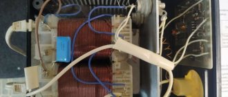
Dismantling the device housing for visual diagnostics
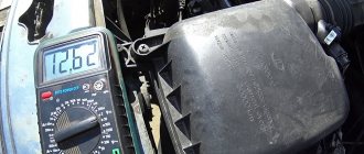
Checking the power transformer unit with an ammeter
Battery won't charge
If a battery that is more than 5-7 years old is not charging , then the answer to the question is: “ why ?” most likely lies on the surface. After all, any battery has its own service life and over time loses some of its basic performance characteristics. But what if the battery lasted no more than 2 or 3 years, or even less? Where then should we look for reasons why the battery does not want to charge? Moreover, this situation occurs not only when recharging from a generator in a car, but even when it is replenished from a charger. Answers must be sought depending on the situation by performing a series of checks followed by procedures aimed at eliminating the problem.
Most often, you can expect 5 main reasons that manifest themselves in eight different situations:
| Situation | What to do |
| Oxidized terminals | Clean and lubricate with special lubricant |
| Broken/loose alternator belt | Stretch or change |
| The diode bridge has failed | Change one or all diodes |
| Voltage regulator faulty | Replace graphite brushes and the regulator itself |
| Deep discharge | Increase the charging voltage or reverse polarity |
| Incorrect electrolyte density | Check and adjust to the required value |
| Sulfation of plates | Perform a polarity reversal, and then several cycles of full charge/discharge with low current |
| One of the cans is closed | Actions to restore a battery with such a defect are ineffective |
Schematic diagram
The starting charger circuit contains a triac voltage regulator (VS1), a power transformer (T1), a rectifier with powerful diodes (VD3, VD4) and a starter battery (GB1). The charging current is selected by the current regulator on the triac VS1, its current is regulated by the variable resistor R2 and depends on the battery capacity.
The input and output charging circuits have filter capacitors, which reduce the degree of radio interference during operation of the triac regulator. Triac VS1 provides regulation of the charging current when the network voltage varies from 180 to 220 V.
The triac wiring consists of R1-R2-C3 (RC circuit), dinistor VD2 and diode bridge VD1. The time constant of the RC circuit affects the opening moment of the dinistor (counting from the beginning of the network half-cycle), which is included in the diagonal of the rectifier bridge through the limiting resistor R4. The rectifier bridge synchronizes the switching on of the triac in both half-cycles of the mains voltage. In the “Regeneration” mode, only one half-cycle of the mains voltage is applied, which helps clean the battery plates from existing crystallization. Capacitors C1 and C2 reduce the degree of interference from the triac in the network to acceptable levels.
The main reasons why the battery may not charge
To understand in detail all the possible malfunctions due to which the car battery does not charge, first of all, clearly define the situation:
| The battery quickly discharges and dies | or he | does not charge at all (does not accept charge) |
In general, when the battery refuses to charge, the following options are allowed:
- plate sulfation;
- destruction of plates;
- terminal oxidation;
- decrease in electrolyte density;
- short circuit
But you shouldn’t worry so much right away, everything is not always so bad, especially if such a problem arose while driving (indicated by a red battery light). It is necessary to consider special cases in which the car battery does not take charge only from the generator or from the charger as well.
The charging system of a car battery contains a number of external devices, on which the performance of the battery itself and the charging process can also greatly depend. To check all external devices, you will need a multimeter (tester); it will allow you to measure the voltage at the battery terminals under different engine operating modes. You will also have to check the generator. But this is only true when the battery does not want to be charged from the generator. If the battery does not take a charge from the charger, then it is advisable to also have a hydrometer to check the density of the electrolyte.
Security measures
When eliminating battery charging breakdowns, you must take into account simple safety measures:
- Do not short-circuit the contact probes on the device. This may cause the device to short out and catch fire. The main board of the charger will fail and cannot be restored.
- When dismantling the battery, it is not allowed to short-circuit the positive and negative terminals connected to the battery. This will cause a short circuit in the on-board network, which will lead to catastrophic consequences. Damage to the electronic control unit and even failure of all electrical equipment may occur.
- If the car owner will restore the operation of the charger on his own, he must carefully select components. It is not allowed to use components that do not correspond to the elements installed on the board. This can lead not only to damage to the charger itself, but also to failure of the battery.
- When checking the charger after repair, the battery will need to be recharged. When performing this task, be sure to unscrew the plugs on the device’s banks if the battery is serviceable. Otherwise, the electrolyte solution may boil. In theory, the battery could explode.
User Alexey Techmaster spoke in detail about precautionary measures, as well as repairing charging equipment for the car’s battery. https://www.youtube.com/embed/NvpyuHqKQeY
https://youtube.com/watch?v=NvpyuHqKQeY
How do you know if the battery is not charging?
The battery does not charge from the generator . The first signal that the battery is not charging is a lit red battery light! And to make sure of this, you can check the battery voltage. There should be 12.5... 12.7 V at the battery terminals. When the engine is started, the voltage will rise to 13.5... 14.5 V. With consumers turned on and the engine running, the voltmeter readings, as a rule, jump from 13.8 to 14.3V. No changes on the voltmeter display or when the indicator goes beyond 14.6V indicates a generator malfunction.
Schemes Scheme Arton BP
The starting charger will help you start the engine of your car in cold weather or with a weakly charged battery and thereby save your time. You can use the Arton BP device to charge 6 and 12 volt batteries indoors. The starting-charging device "Arton BP" was repaired, who will explain the electrical circuit in full and specifically the node attached to contacts 1,2,3,4 of the xs1 connector on the side of the control board - the connection between alternating and direct voltages. The control board is factory, apparently not soldered. The power supply indicates a 10A fuse, although the power consumption does not exceed W. Sincerely, Victor.
What can you do when your car battery is not charging?
The first step is to find out the cause, and only then take action to eliminate it. To do this, you need to measure the voltage at the battery terminals, check the level, density of the electrolyte and its color. It is also, of course, necessary to visually inspect the surface of the battery, the car wiring, and also to determine the current leakage.
Let us consider in detail the possible consequences of each of the reasons for poor battery performance, and also determine what needs to be done in a given situation:
Oxidation of contact terminals
both prevents good contact and contributes to current leakage. As a result, we get a quick discharge or unstable/absent charging from the generator. There is only one way out - check not only the condition of the battery terminals, but also the condition of the generator and the ground of the car. Heavily oxidized terminals can be removed by cleaning and lubricating the oxides.
Generator malfunction
(belt, regulator, diodes).
Belt break
you would probably notice, but the fact is that even a slight loosening of the tension can contribute to slippage on the pulley (as well as oil ingress). Therefore, when powerful consumers are turned on, the light on the panel may light up and the battery will discharge, and on a cold engine a squeaking sound can often be heard from under the hood. This problem can be eliminated either by tensioning or replacement.
Diodes
in normal condition they should pass current only in one direction; checking with a multimeter will make it possible to identify the faulty one, although often they simply change the entire diode bridge. Improperly functioning diodes can cause both undercharging and overcharging of the battery.
When the diodes are normal, but they get very hot during operation, it means the battery is being overcharged. The regulator is responsible for the voltage . It is better to change it immediately. In a situation where the battery is not fully charged, you need to pay attention to the generator brushes (after all, they wear out over time).
During deep discharge
, as well as with a slight shedding of the active mass, when the battery does not want to be charged not only in the car from the generator, but even the charger does not see it, you can reverse the polarity or give a high voltage so that it grabs the charge.
Starter charger Arton BP 02 in Yekaterinburg
In simple fire safety systems of autonomous or centralized operation, a 2-zone control panel 02P from the popular Arton brand is used. The device is equipped with a keypad and many indicators. For configuration and monitoring, a keyboard is used or performed remotely from the control panel. Up to 32 active, passive or combined detectors can be connected to each alarm loop. The output is activated in the event of a fire, malfunction of a sensor, device, main or backup power supply, alarm, etc. Connection of 4 independent sirens is provided.
Causes of malfunction of starter car batteries
The service life of a battery discharged by 25% is significantly reduced if:
- malfunction of the generator and voltage regulator;
- starter malfunctions leading to an increase in current or an increase in the number of attempts to start the engine;
- oxidation of power wire terminals;
- constant use of powerful consumers during long periods of idle time in traffic jams;
- repeated cranking of the crankshaft with the starter on short trips.
A reduced electrolyte level during battery operation is also a key reason for rapid battery failure. Therefore, the cause of the malfunction may be:
- Rare electrolyte level monitoring. In summer, checking should be done more often because high temperatures promote rapid evaporation of water;
- Intensive use of the car (when the mileage is more than 60 thousand km per year). Requires checking the electrolyte level at least every 3-4 thousand kilometers.
Security measures
When eliminating battery charging breakdowns, you must take into account simple safety measures:
- Do not short-circuit the contact probes on the device. This may cause the device to short out and catch fire. The main board of the charger will fail and cannot be restored.
- When dismantling the battery, it is not allowed to short-circuit the positive and negative terminals connected to the battery. This will cause a short circuit in the on-board network, which will lead to catastrophic consequences. Damage to the electronic control unit and even failure of all electrical equipment may occur.
- If the car owner will restore the operation of the charger on his own, he must carefully select components. It is not allowed to use components that do not correspond to the elements installed on the board. This can lead not only to damage to the charger itself, but also to failure of the battery.
- When checking the charger after repair, the battery will need to be recharged. When performing this task, be sure to unscrew the plugs on the device’s banks if the battery is serviceable. Otherwise, the electrolyte solution may boil. In theory, the battery could explode.
User Alexey Techmaster spoke in detail about precautionary measures, as well as repairing charging equipment for the car’s battery. https://www.youtube.com/embed/NvpyuHqKQeY
https://youtube.com/watch?v=NvpyuHqKQeY