The gearbox in a car (hereinafter referred to as the gearbox) is designed to change and transform due to the influence (switching) of the engine gear ratio. It allows you to change the rate of acceleration, increase speed characteristics at different speeds and makes the wheels rotate at different speeds. Sometimes every driver, when operating a car, is faced with the issue of servicing or repairing a gearbox on a VAZ 2114. Some began to notice problems in this unit, others are interested in its uninterrupted and long service, since this element is one of the main ones in the overall structure of the car.
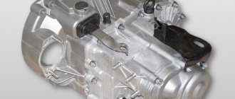
VAZ 2114 gearbox device
Box removal process
Removing the VAZ 2114 box is quite simple, although there are some peculiarities, so it is still advisable to have an experienced partner next to you for the first time.
Tools
- a set of keys;
- Screwdriver Set;
- WD-40 fluid in case you can’t unscrew some part;
Rust converter WD-40
Gears are difficult to shift
Spontaneous gear disengagement occurs
Gears are switched on with noise and crackling
There is an oil leak from the gearbox
- container for draining old transmission oil;
- new oil (if the replacement was carried out a long time ago);
- rags;
- board.
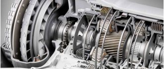
Gearbox VAZ 2114 disassembled
Stages
Since you will have to work under the car, it is better to place the VAZ 2114 car on a pit or overpass; a car lift would be a good solution, otherwise you will have to resort to jacks.
- First you need to remove the terminals and remove the battery.
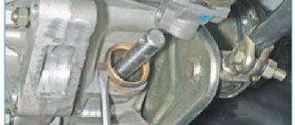
- Drain the oil from the gearbox into a prepared container by unscrewing the drain plug.
- We remove the starter.
- Remove the clutch cable.
- We disconnect the block with wires from the speed sensor, after compressing the spring.
- We unscrew the bolt attaching the ignition bracket to the gearbox. Then unscrew the remaining bolts.
- Under the car we find and disconnect the block of wires leading to the reverse sensor.
- Unscrew the bolts securing the linkage bracket to the gearbox.
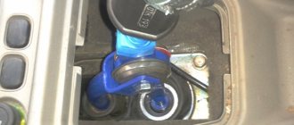
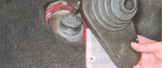
- Having first loosened the gear shift rod clamp, we pull it out, pushing it back.
- We dismantle the wheel drives. You can leave the right one.
- In order for the gearbox to be removed without any complications, unscrew the bolts with which the left ball joint is attached to the steering knuckle.
- We disconnect the lower mount of the gearbox to the engine - sometimes you can get by by simply loosening the tightening of the bracket.
- After unscrewing the bolts, remove the transmission housing cover.
- Unscrew the bolt on the left of the gearbox.
- We carefully and carefully hang the engine using a board or other device.
- At the bottom of the car, unscrew the nut securing the left motor mount.
- We unscrew the two nuts with which the rear motor mount is attached to the body.
- We unscrew the two bolts with which the rear engine support is attached to the transmission (the second key is used to keep the nuts from turning), and remove the support.
- We move the box along the guides.
- This completes the process of removing the box; after completing all the necessary tasks, assembly occurs in the reverse order.
- When you put the box in place, do not forget to adjust the clutch and fill it with new oil.
Latest comments:
Gear shift mechanism
The gearshift mechanism is usually mounted in gearbox covers and is used to select, engage, and disengage gears. In addition, devices are installed in the gear shift mechanism that prevent the inclusion of two gears at the same time and prevent spontaneous gear shifting.
The main requirements for this mechanism are ease and simplicity of gearbox control, noiseless and smooth gear shifting, reliable locking of the engaged gear, prevention of simultaneous engagement of two or more gears, as well as protection from engaging a gear opposite to the vehicle's movement while moving. In addition, the activation mechanism must be reliable, durable, not requiring complex adjustments and easy to maintain. Malfunctions of the gear shift mechanism can lead to damage to parts and failure of such an expensive unit as a gearbox.
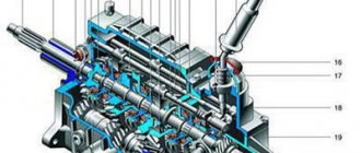
The gearbox shift mechanism of a truck (Fig. 1, a) consists of three rods, three forks, three clamps with balls, a fuse for engaging first gear and reverse gear and a locking device. Rods 8, 9, 11 are located in the holes of the internal bosses of the crankcase cover 1. Forks 5, 7, 10 are attached to them, connected to the synchronizer carriages and to the movable gear wheel for engaging first gear and reverse gear.
Clamps 4 hold the rods in the neutral or engaged position, which prevents spontaneous gear disengagement. Each retainer is a ball with a spring installed above the rods in special sockets in the crankcase cover. The rods for the clamp balls have special grooves (holes). Moving the rod with the fork, and therefore the synchronizer, is only possible when force is applied by the driver, as a result of which the ball sinks into its seat.
Device
To understand the essence of repairing, disassembling and assembling a gearbox, first of all you need to get acquainted with its structure. In the case of the VAZ 2109, the box structure is as follows:
- On the input shaft there is a block of drive gears that are in constant mesh with the driven gears of the gears when moving forward;
- The second shaft has driven gears with needle bearings. There is also a pair of synchronizers located there;
- The secondary shaft is created together with the drive gear of the main transmission;
- The driven gear of the main gear is attached to the flange of the two-pinion differential box;
- Differential bearings are always mounted with interference, which is adjusted by selecting rings of different thicknesses.
Checkpoint diagram
Gearbox configurations
Below are the most successful gearbox configurations depending on the engine. For a more detailed selection, you can use a calculator on the Internet.
- The most suitable gearbox configuration for a civilian naturally aspirated engine: 18 row gearbox + main pair 3.9.
- The most suitable gearbox for a sports naturally aspirated engine: 7th row gearbox + main pair 4.3.
- The most suitable gearbox configuration for a turbo civilian engine: row 104 + main pair 3.5.
The differential is two-satellite, the tension is adjusted by different thicknesses of the adjusting ring.
Sports cars often use a differential lock.
A differential lock is a mechanism that locks the differential so that both wheels rotate evenly. Initially, locking was used on SUVs to ensure that the front and rear axles rotated evenly.
In our case, screw locks are especially popular, because they are easily installed in the gearbox, increase cross-country ability on wet roads, and provide an advantage during acceleration due to uniform constant rotation of the wheels.
Malfunctions and their elimination
Gearbox repair largely depends on the nature and type of fault. There are several options for the breakdown of this unit, in each of which appropriate actions should be taken to eliminate them.
Malfunction
Possible reasons
What do we have to do
There is noise in the gearbox
- The teeth on the gears are worn out;
- Bearings are worn out;
- The oil level in the gearbox has decreased
- Add oil;
- Replace worn bearings;
- Replace seals if necessary
- The clutch is not fully depressed;
- The rod that controls the gear shift mechanism has become deformed;
- The integrity of the jet thrust has been compromised;
- The joint or rod that selects the gear is loose;
- The speed change drive is incorrectly adjusted;
- The plastic components of the gear shift drive are broken
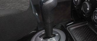
Features of manual transmission VAZ 2114
On domestic cars, namely the VAZ 2114, the gearbox is manual with 5 speeds. The VAZ 2114 is a very popular model among Russian car enthusiasts, especially among young people, due to its reasonable price and the ability to independently repair almost all components and parts, which reduces the time and financial costs of servicing the car.
It is easier to find and repair any fault in the VAZ 2114 gearbox at the initial stage than to replace it in full with a new spare part in the future.
Before considering the symptoms of breakdowns, you first need to look at what the gearbox on the VAZ 2114 consists of. This will simplify the accurate “diagnosis” of the malfunction. The VAZ 2114 gearbox diagram is located below.
Dismantling
To dismantle the box, we recommend that you rely on the instructions, strictly follow the sequence and reinforce your skills with visual videos.
- Disconnect the negative terminal from the battery and drain the oil from the gearbox system.
- Unscrew the bolts that hold the crankcase guard in place and remove it.
- Disconnect the ground (wire) from the clutch housing.
- At the end of the clutch cable, loosen the tension on the nuts slightly.
- Remove the cable end from the clutch lever.
- Disconnect the block from the traction relay.
- Disconnect the wire going to the starter traction relay.
- Dismantle the starter itself directly.
- Disconnect the drive rod from the joint tip. We are talking about traction, which switches gears.
- Disconnect the cable from the car's speedometer drive.
- Unscrew the tie rod ball joint.
- Remove and press the steering rod hinge pin out of the strut swing arm.
- The shank of the inner CV joint of the front wheel drive should be pressed out and moved to the side.
- Disconnect the second CV joint.
- Remove the clutch housing shield.
- Release the gearbox from the fasteners holding it to the engine.
- Remove the box.
Carefully remove the gearbox
Be sure to move it horizontally away from the motor before directly removing the box. Then disengage the input shaft. Be careful not to damage the clutch spring petals.
Disassembly
Having removed the gearbox, you can proceed directly to the main thing - disassembly. This will allow you to change damaged elements as you work, identify existing faults and solve problems on your own.
- Clean and thoroughly wash all external surfaces of the gearbox.
- Place the box in a vertical position and remove the back cover.
- Remove the clutch cable bracket, then use a rubber hammer to knock the rear cover off the gearbox.
- Remove the old gasket. She will be replaced.
- Engage any of the two gears - 3 or 4.
- Unscrew the bolt that holds 5th gear, then turn it on.
- Simultaneously turning on the indicated speeds will allow you to fix the shaft and prevent it from turning.
- Unscrew the nut on the secondary shaft, and then on the primary one.
- Remove the 5th speed synchronizer along with the fork.
- Remove the fork from the coupling. Remove the synchronizer as carefully as possible. If you allow the clutch to move away from the hub, the spring-loaded balls that secure the synchronizer will simply fall apart.
- Remove the 5th speed synchronizer locking ring.
- Remove the 5th speed driven gear from the output shaft.
- Remove the thrust ring located on the needle bearing.
- Remove the needle bearing itself from the 5th speed gear.
- Remove the drive gear from the drive shaft and remove the bearing plate.
- Now the needle bearing bushings should be removed from the secondary shaft, and the thrust washer should also be removed.
Repair of the secondary shaft (Part I)
Secondary shaft of the gearbox: 1 – secondary shaft;
2 – 4th gear gear; 3 – gear III gear; 4 – 2nd gear gear; 5 – 1st gear gear; 6 – main gear drive gear; 7 – inner ring of the front shaft bearing; 8 – synchronizer of 1st and 2nd gears with a gear ring for reverse gear; 9 – synchronizer for 3rd and 4th gears; 10 – rear shaft bearing 1. With slight force, clamp the shaft into a vice with pads on soft metal jaws.
2. Using two mounting paddles, press down the output shaft rear bearing.
4. ...4th gear driven gear...
5. ...4th gear needle bearing and mark it.
Be sure to label the needle bearings and bushings according to the gear number. When assembling, they must be installed in the same places. The most convenient way is to insert the corresponding needle bearing and (where available) bushing into the gear...
...and tie them with rope or wire.
6. Remove the spacer ring.
7. Using two mounting blades, move the 3rd and 4th gear synchronizer through the 3rd gear gear from the shaft splines.
8. Remove the 4th gear needle bearing bushing.
9. Remove the 3rd and 4th gear synchronizer with the 4th gear blocking ring.
10. Mark the locking ring relative to the synchronizer clutch.
Be sure to mark the locking rings in relation to the coupling. During operation, the teeth of the rings are worn in to the teeth of the coupling, so during assembly it is necessary to install the rings in the same position. If you do not intend to disassemble the synchronizer, tie it with rope or wire to prevent it from falling apart.
11. Remove the blocking ring of the 3rd gear and mark it relative to the synchronizer clutch.
12. Remove the 3rd gear gear.
13. Remove the 3rd gear needle bearing and mark it.
14. Remove the retaining ring of the thrust half-rings...
15. ...and two persistent half rings.
16. Remove the locking ball from the hole on the shaft.
17. Remove the 2nd gear.
18. Remove the 2nd gear needle bearing and mark it.
19. Remove the snap ring.
20. Place the 1st gear gear shaft on the jaws of the vice and, using a wooden mallet on the end of the shaft, press the 1st and 2nd gear synchronizer off the shaft splines.
Source