Having appeared 6 years after the start of operation of the plant in Tolyatti, the VAZ 2121 car for many years secured the primacy of an off-road model with great capabilities. And although the transmission was a fairly revolutionary solution for the domestic automobile industry, the electrical circuit was used virtually unchanged.
The VAZ 2121 wiring was borrowed from existing models
Like most other parts, the SUV was borrowed from its passenger counterparts. In particular, the electrical wiring of the VAZ 2121 was the wiring of the VAZ 2106 after minor modifications.
In fact, the electrical circuit is:
- A single-wire circuit, where the role of the second wire is played by the car body;
- All actuators and control devices have outputs from the negative terminal to ground;
- The main circuits are protected by fuses.
Find out also about all the nuances of wiring a VAZ 2114.
Ignition system
The operation of the internal combustion engine installed on the VAZ 2121 car is based on a classic scheme, a video of which is shown in driving courses:
- The generator produces electric current;
- The ignition coil increases its power;
- The ignition distributor supplies electrical impulses to the spark plugs when the piston reaches TDC;
- The spark plugs ignite the air-fuel mixture in the engine cylinders.
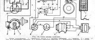
Factory wiring diagram of VAZ 2121: elements of the ignition system
The photo shows the following components:
- From pos. 3 to 12 – ignition coil and its structure;
- From pos. 13 to 20 – spark plug;
- From pos. 21 to 42 – ignition distributor (distributor).
For reference: The distributor slider, which is responsible for closing the contacts with the high-voltage wires going to the spark plugs of each cylinder, is shown separately. In the diagram presented, it is indicated by pos. 41-45.
Read also about the features of the VAZ 2101 wiring diagram.
Engine modernization
The all-wheel drive transmission of the VAZ 2121, in addition to significant advantages, also had domestic disadvantages. In particular:
- Fuel consumption was quite high compared to passenger cars (13.4 liters per 100 km in urban conditions and off-road);
- This was reflected in operating costs - the price of 1 km was much more expensive for the owners. And the power of the existing engine was insufficient for harsh off-road conditions.
For reference: the automaker, by modernizing the existing engine, increased its technical parameters. In particular, the volume increased from 1480 cubic meters. cm up to 1680 cc see Cars with such a power unit received the factory index VAZ 21214.
An increase in engine displacement and the use of a non-contact ignition system led to the need to modernize the electrical circuit in the engine compartment. Replacing the VAZ 2121 wiring solved this problem completely.
Electrical wiring for VAZ 21214 installed on a car with a 1680 cc engine. cm
Ignition system modernization
Since the high-voltage coil is traditionally responsible for the sparking power, the automaker has made changes to its operation. In particular, the wiring on the VAZ 2121 was supplemented with a harness that connected the switch and other components of the ignition system.
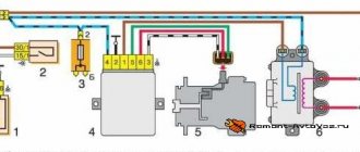
Contactless ignition system VAZ 21214
This factory manual contains:
- Ignition switch acting as an electrical circuit switch with pins 30/1 and 15;
- Ignition relay with pins 85,86,30 and 87;
- Switch with 6-pin terminal block;
- Upgraded ignition coil with terminals “B” and “K”;
- Distributor (ignition distributor);
- Candles.
How to check if the battery is charging
Before looking for a fault in the charging circuit, it is necessary to find out whether this very undercharging actually exists. After all, the problem could be:
- in charge indication circuits;
- in a faulty battery.
Healthy! To check, we use a DC voltmeter with a measurement limit of 20 V or a multimeter (tester). Both pointer and digital devices are suitable. The accuracy of both will be sufficient.
We connect a voltmeter or multimeter turned on in the DC voltage measurement mode to a limit of at least 20 V. We start the engine and raise its speed to 1,000 per minute. If the voltmeter shows a voltage in the range of 13.5-14.2 V, then the charging circuits are OK. The fault is with the charging indication elements that mislead us, or with the battery.
In the first case, we check the control circuits (their circuits and testing algorithm will be described below), in the second case, we test the battery using a load fork.
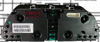
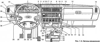
Dashboard
For subsequent modifications of the VAZ 2121, the instrument panel was thoroughly redesigned. In particular, the design and location of the warning lamps have changed, and new scales have appeared on the instrument panel indicators.
Original wiring diagram for VAZ 21214 – instrument panel and warning lamp harness
Conclusions: the owners of the VAZ 2121 car often serviced it themselves. And servicing electrical systems is impossible without original circuit diagrams. This was especially true for modernized versions, where changes were made to the operation scheme of components and assemblies.
Read also about the features of the VAZ-2110 wiring diagram (injector).
The belt has stretched or broken
The drive belt for the generator and water pump from the engine shaft does not break very often, but it stretches regularly. As a result, it begins to slip on the pulleys, the generator, especially under load (high beams plus air conditioning, etc.), does not develop the required speed, and the voltage at its output drops. As a result, the battery is undercharged and may even be discharged, helping the “exhausted” generator and feeding the on-board network with its energy.
Poor belt tension is characterized by a drop in the voltage of the on-board network and a peculiar whistle when the speed increases sharply, especially in wet weather. The problem is treated quite simply. Find the generator mounting bolt on the tension bar. We loosen it, use a pry bar to move the generator to normal belt tension and tighten the bolt.
Expert opinion
Alexey Bartosh
Specialist in repair and maintenance of electrical equipment and industrial electronics.
Ask a Question
Healthy! An over-tightened belt is just as bad as a loose one. It can tear, leaving you spending the night on the road, and will very quickly stretch again. So you shouldn’t tighten the belt “for future use”. Its tension force should be approximately the same as indicated in the diagram below.
Main and additional fuse blocks
Heater fan, rear window defroster, rear wiper and washer system, windshield washer pump
Steering column switch, windshield wipers, hazard warning lights, breaker relay (in turn signal mode), reverse light, instrument cluster (coolant temperature gauge, fuel level gauge, tachometer, warning lights: turn indicators, differential lock, parking brake, emergency condition of the working brake system, insufficient oil pressure, fuel reserve, battery charge)
Left headlight (high beam), high beam indicator lamp
Right headlight (high beam)
Left headlight (low beam)
Right headlight (low beam)
Side light lamps in the left front and left rear lights, license plate lights, side light indicator lamp
Side light lamps in the right front and right rear lamps, backlight lamps for the instrument cluster, cigarette lighter, switches, heating and ventilation control unit
Hazard switch, breaker relay (in hazard mode), heated tailgate glass relay contacts
Sound signal, interior lamps, brake lamps in the rear lights
Fog light relay contacts in rear lights
Summarizing
The need to understand the wiring diagram may arise if there are malfunctions in the operation of the system and they need to be eliminated. Of course, complex malfunctions associated with the operation of the generator unit and other devices that are not simple in terms of design will be problematic to solve in a garage without certain knowledge. However, even simple knowledge of the electrical circuit and the ability to decipher the symbols can greatly help the car enthusiast during repairs. In addition, the need to understand wiring may also arise if you decide to upgrade your speakers or install a more advanced audio system.
Electrical diagram of VAZ-Front
These cookies do not store any personal information. Level indicator and fuel reserve sensor. This category only includes cookies that ensures basic functionalities and security features of the website. Windshield wiper motor. Owners of domestic SUVs often use trailers - to connect them correctly, you also need to understand the wiring. Air duct of the starting device.
With sufficient vacuum in the nozzles of the main metering systems, the fuel is mixed in emulsion wells with air entering through the main air jets 6 and 13, and in the form of an emulsion is sucked into the diffusers of the mixing chambers. Only after this can you resort to the possibility of easier starting of the car.
Out of these cookies, the cookies that are categorized as necessary are stored on your browser as they are as essential for the working of basic functionalities of the website. Handbrake sensor.
Main air jet of the first chamber. The second begins to open and operate when the throttle valve of the first chamber is opened more than two-thirds. As mentioned above, each electrical circuit of equipment in VAZ cars has its own characteristics. Rear fog lamp switch. Closing search Niva 21213
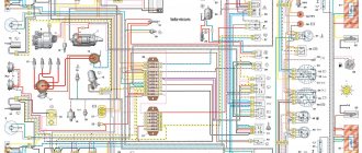
The second version of the NIVA 21213 scheme
1. Headlights 2. Headlights 3. Headlight wiper motors 4. Horn 5. Headlight washer motor 6. Windshield washer motor 7. Generator 8. Side turn signals 9. Battery 10. Heater motor 11. Additional heater motor resistor 12 Windshield wiper breaker relay 13. Starter 14. Windshield wiper motor 15. Carburetor limit switch 16. Carburetor solenoid valve 17. Carburetor solenoid valve control unit 18. Switch 19. Spark plugs 20. Ignition distributor sensor 21. Control sensor oil pressure lamps 22. Temperature indicator sensor 23. Socket for a portable lamp 24. Ignition coil 25. Brake fluid level warning lamp sensor 26. Relay for turning on the headlight cleaners and washer 27. Relay for turning on the heated rear window 28. Relay for turning on the high beam headlights 29 . Headlight low beam relay 30. Ignition on relay 31. Starter on relay 32. Differential lock warning lamp switch 33. Exterior lighting switch 34. Cigarette lighter 35. Brake light switch 36. Reverse light switch 37. Turn signal breaker relay and alarm 38. Main fuse block 39. Additional fuse block 40. Illumination lamps for heater control levers, 41. Rear fog light switch 42. Rear window heating switch 43. Heater motor switch 44. Rear window wiper and washer switch 45. Emergency switch alarm 46. Ignition switch 47. Carburetor choke warning lamp 48. Instrument lighting switch 49. Steering column three-lever switch 50. Carburetor choke warning lamp switch 51. Rear window washer motor 52. Courtesy lamp switches located in the door pillars 53. Interior lamps 54. Instrument cluster 55. License plate lights 56. Parking brake warning lamp switch 57. Level indicator and fuel reserve sensor 58. Tail lights 59. Rear window wiper motor 60. Rear window heating element 21213.
Features of the modification
Electrical diagram describing the VAZ 2121 Niva carburetor.
First of all, the changes affected the engine control system and control devices. In particular:
- The wiring diagram for Niva 21213 received an additional wiring harness in the engine compartment for connecting a microcontroller and sensors;
- On the Niva model of recent years of production, a more advanced power unit with the VAZ-21214 index is installed. Instead of a carburetor, it has a fuel frame with injectors from GM. The price of a car with injection has increased because of this;
- The instrument panel has changed - the design is borrowed from the VAZ 2108 model.
Ignition system
The VAZ 21213 engine uses a non-contact ignition system consisting of:
- ignition distributor sensor (marking 3810.3706). It is responsible for creating control pulses supplied to the electronic switch;
- switch (model marking – 3620.3734) in climatic version U2.1 (corresponds to GOST 15150);
- ignition coils (marking 27.3705).
For reference: this device provides increased spark energy, which helps start the engine in cold weather, and also improves the performance of the power unit when operating the vehicle on low-quality fuel.
Dashboard
A modified instrument panel appeared on the car. In particular, instead of a voltmeter, the manufacturer installed a low battery discharge lamp (no. 12 in the diagram).
Tip: if you often operate your car in off-road conditions, you can buy and connect a voltmeter to the instrument panel yourself. It is more informative than a warning light and will allow you to identify electrical system faults long before the battery discharges.
Review of the composition and location of elements and indicators of the VAZ 2110 instrument panel
The main reference point for driving a car is the dashboard. A serviceable VAZ 2110 instrument panel informs the driver of all the main characteristics of the devices and allows for optimization of control. Each car has its own combination of devices; they can be located completely differently on the dashboard.
Old-style VAZ 2110 instrument panels:
Instrument panel of VAZ 2110 with a mechanical odometer. Article 2110-3801010 VDO instrument panel with one window. Article: 2110-3801010-08 2110-380101-02Schetmash instrument panel with one window. Article: 2110-3801010-05 2110-3801010-06 Instrument panel Automotive instrument with one window. Article: 2110-3801010-04 VDO instrument panel with two windows.
Article: 2115-3801010 2115-3801010-04Schetmash instrument panel with two windows. Article: 2115-3801010-03 2115-3801010-T 2115-3801010-03 Instrument panel Automatic instrument, with 2 windows and zeros before the numbers. Article: 2115-3801010-05 Automatic instrument panel With 2 windows and without zeros in front of the numbers. Article number: 2115-3801010-01 VDO instrument panel (VAZ-21106 with an Opel engine).
Article 21106-3801010
New instrument panels:
VDO instrument panel. Article 1118-3801010 Instrument panel Schetmash. Article: 1118-3801010-12 2170-3801010-01 1118-3801010-13 2170-3801010-03 Instrument panel Auto device. Article: 1118-3801010 1118-3801010-01 1118-3801010-02 541.3801010 2170-3801010-02
Functional
The pinout of this VAZ model is as follows:
- Electronic speedometer;
- Electronic type tachometer;
- Coolant temperature indicator;
- Fuel level indicator in the tank;
- Indicator lamps in the amount of 12 pieces.
Instrument panel diagram
This combination is fixed on a special board, in a separate socket using two screws. The panel is removed after unscrewing them. The accuracy of the board is ensured by the printing method of production and installation of this pinout; foil getinax is used for printing.
Instrument panel pinout
* - on VDO and Schetmash panels with two windows, an external VDO temperature sensor is used, mounted under the bumper. Not used on panels with one window. For panels with a mechanical odometer, this contact receives a signal from terminal “W” of the fuel level sensor (FLS).
Color coding for wiring of old-style panels:
Connecting wires to the VDO panelConnecting wires to the "Schetmash" panel, Kursk Connecting wires to the "AP" panel, Vladimir
The instrument panel is securely attached to the rear of the panel housing and all instruments work efficiently. If the readings of one of the devices are incorrect, repair or replacement of parts should be carried out.
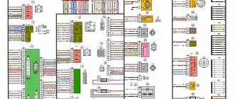
24.4. Interactive diagram of electrical equipment of VAZ-21213 cars
Main air jet of the first chamber. Rear window washer motor.
Main unit Additional. Brake light switch. In addition to the car electrical wiring itself, with the designation of all elements of headlights, sensors, switches and signals, a relay block and diagrams are provided.
Bracket for fastening the rod shell.
Adjusting screw 1 allows you to adjust the amount of opening of the damper. The second black ends of the wires are also brought together to a point with a mass equal to the connected one. Due to the risk of short circuits, do not pry open fuses with metal tools or screwdrivers unless the corresponding circuits are de-energized.
Crankcase gas suction pipe. Oil pressure warning light sensor. Rear fog lamp switch. By closing this banner and scrolling this page, you agree to the use of cookies.
Main air jet of the first chamber. Heater switch. The injection system power supply circuit is protected by a fuse-link made of wire with a reduced cross-section of 1 mm2. The fuel passes through the valve, economizer jet 23, is added to the fuel passing through the main fuel jet 36, and equalizes the richness of the mixture.
Electrical diagram of VAZ 21213 Niva Carburetor
Windshield wiper motor. Headlight switch.
Sound signals.
Throttle valve of the first chamber. 3. Charging system - 2 It should be noted that in this case the contact pad has also undergone certain changes. Level indicator and fuel reserve sensor. Necessary Always Enabled Necessary cookies are absolutely essential for the website to function properly.
Differences in wiring As for wiring in cars and others, it can be done in different variations, which makes it easier to maintain the system at home. Those fans of domestic SUVs who were willing to pay such a price could only purchase a car abroad. Front lights.
Rear fog lamp switch. For example, in the case of a carburetor, the electrical circuit for charging the battery and ignition system is not protected, unlike injectors.
Turn signal relay VAZ classic. Testing, diagram, principle of operation.