Ignition switch VAZ 2107
The ignition switch (IZ) of the VAZ 2107 is an electromechanical type device. It is located under the dashboard and is attached to a bracket welded to the left side of the steering column shaft.
Purpose of the ignition switch
The main function of the protection system is to synchronize electrical systems when starting and operating the vehicle. When you turn the key in the lock, current begins to flow to the starter solenoid relay, to the ignition system, to instrumentation and lighting devices, heater, etc. When the ignition switch is turned off, most of the electrical equipment is completely de-energized, protecting the battery from discharge. At the same time, the anti-theft mechanism is activated, blocking the steering wheel at the slightest turn.
The key in the ZZ VAZ 2107 can occupy four positions, three of which are fixed:
- 0 — “Disabled.” Electrical wiring is de-energized. The key cannot be removed from the lock; the anti-theft mechanism is disabled.
- I - “Ignition”. The engine spark system, generator excitation, instrumentation, exterior lighting, windshield wiper blades, heater and turn signals are included. The key cannot be removed from the lock; the anti-theft mechanism is disabled.
- II - “Starter”. Current is supplied to the starter. The position of the key is not fixed, so it must be forcibly held in this position. It cannot be removed from the lock.
- III - "Parking". Everything is turned off except the sound signal, side lights, windshield wiper blades and interior heating stove. When the key is removed from the lock, the anti-theft mechanism is activated. When turning the steering wheel in any direction, it will be locked. To confirm the locking, a sound signal will be heard - a click. To disable the anti-theft system, you need to insert the key into the lock, set it to position “0” and smoothly turn the steering wheel in any direction until it unlocks.
When descending a Zhiguli from a mountain or driving at neutral speed, you must not turn off the engine and remove the key from the lock. Such actions will lead to jamming of the steering wheel and the creation of an emergency situation on the road due to difficulties in controlling the car.
Ignition switch connection diagram
On the new VAZ 2107, all the wires going to the ignition switch are collected into one plastic chip, which is not difficult to connect. To disable the lock, you simply need to remove this chip. If the wires are placed on the contacts separately, the connection should be made according to the following scheme:
- the red wire (starter) is connected to pin 50;
- to pin 15 - double blue wire with a black stripe (ignition, heater, instruments on the front panel, heated rear window);
- to pin 30 - pink wire (battery plus);
- to pin 30/1 - brown wire (battery plus);
- to the INT contact - black wire (dimensions, rear brake lights and headlights).
The ignition switch of the VAZ 2107 is connected according to a scheme that is universal for all classic VAZ models.
Ignition switch device
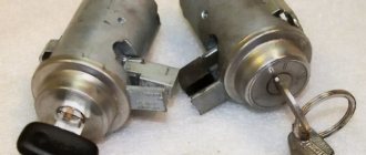
The VAZ 2107 ignition switch is a cylindrical body that contains a cylinder and a contact mechanism, with a protrusion for fixing the steering wheel. At one end of the cylinder there is a recess for a key, at the other there are contacts for connecting electrical wiring. Each key is individual, which provides an additional guarantee against theft. The lock consists of two parts connected by a leash. In the upper part there is a cylinder (locking device), in the lower part there is a contact group.
The lock
The ignition switch has two tasks:
- the main one is rotation of the movable disk of the contact device;
- additional - steering wheel lock when the ignition is off.
The locking is carried out using a movable locking pin, which, when turning the key clockwise, is partially retracted inside the lock body. When the key is rotated in the opposite direction, the finger extends, and when the key is pulled out, the finger fits into a special recess in the steering column. At the same time, a loud click is heard.
To turn, use a leash that:
- ensures rotation of the movable disk of the contact mechanism;
- fixes the lock in the desired position using holes, balls and springs.
Ignition switch contact mechanism
The contact group of the lock consists of two parts:
- movable disk with conductive plates;
- a fixed plastic block in which electrical wiring contacts are fixed, having special protrusions at the point of contact with the movable disk.
When the key is turned, the plates on the disk close or open the necessary contacts on the block, turning on or off the corresponding components and mechanisms.
Exactly three switched contacts
One line through which current is supplied, and only one ignition circuit - this solution is typical for all VAZ cars, if we talk about the “2110”, “2170” and later families. Even in Grants, produced since 2012, the additional ignition circuit did not appear. In general, with the transition to the “Ten” family, three “significant” terminals of the lock remained:
- Contact "30";
- Terminal “15” (can be designated as “15/1”);
- Terminal "50".
The ignition switch circuit looks trivial, even if we talk about the Lada 2110.
The Tens connector has 8 terminals. And in Priora, as well as in Grant and Kalina, this number is reduced to three (Fig. 2).
Of the 8 terminals available in the VAZ-2110 connector, the 7th and 8th simply duplicate each other. Two more are connected to the button, and another pair of terminals are connected to the lamp.
The lock connector of all VAZ models, starting from “2170”, is equipped with only three contact terminals. And the additional connector, which is equipped with a pair of terminals, is connected to the immobilizer in these cars.
The “3” mark has disappeared from the “Tens” lock cylinder. And until now, VAZ produces just such locks, where the key can be installed in one of the following positions:
- "Turned off";
- "Ignition";
- "Start".
The presence of the “Parking” mode, as you can see, is not provided here.
How to change the ignition switch on a VAZ 2106
Ignition coil of cars VAZ 2104, 2105, 2107
Ignition switch VAZ-2106: checking, removal and installation
Preparatory work
Before proceeding directly to removing the ignition switch, it is necessary to perform a number of actions. First of all, you need to disconnect the negative battery.
This way, all electrical systems will be de-energized, and you can safely begin work. After this, it is advisable to remove the covers on the steering column.
This is not difficult to do - you just need to have a screwdriver with you and apply a little effort.
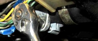
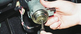
After the casing has been dismantled, it is advisable to clean the surface of the lock from various types of contaminants. If you look closely, you can find the wiring harness block. It needs to be disconnected from the contacts of the VAZ ignition switch.
All work must be done carefully so as not to damage the wiring. As for the tools, we only need a flat-head and Phillips screwdrivers, as well as a multimeter to check the functionality of the device.
Now you can proceed directly to removing the device.
Ignition switch VAZ-2106: dismantling
After all the preparatory work, you can proceed to the most important part. To do this, we must insert the key into the ignition and turn it to position “0”. Next, we need to unlock the steering wheel: the anti-theft device is turned on, therefore, we need to turn the steering wheel left and right together with the key, after which it will turn off.
Take a Phillips screwdriver and unscrew the mount to the bracket. There are two screws: one on one side of the lock, the second on the other. After we remove the screws, we will see the lock retainer in the bracket.
To get the device, you need to push in the latch and pull out the ignition switch of the VAZ-2106 by hand. At this point the work can be considered completed.
Next we need to understand the electrical circuit, detect and eliminate faults in the wiring, since this is where they most often arise. For this we will use a pre-prepared multimeter.
Lock diagram and check
First of all, you need to deal with the wiring. In principle, there is nothing particularly complicated here. When the key is in position one, a contact called 30-INT is turned on. He is responsible for lighting, windshield wipers, and washers.
Also in this position, contact 30/1-15 is activated. The circuits turn on the heater, heated rear window, turns, the generator winding is excited, etc. The carburetor valve and ignition system are also ready to start working.
As for the markings, you can see them on the wiring. It is also schematically depicted on the castle. To check the contact group, you must use an ohmmeter. The probes of the device are connected to the terminals of the ignition contacts. This way the switching is checked.
This is the diagram of the VAZ-2106 ignition switch, and as noted above, there is nothing complicated here.
Replacing the ignition switch of a VAZ-2106
If the fault lies in the contact group, then it needs to be replaced.
You can do this as follows. There is a special groove in the ignition switch housing. Using a screwdriver, we pry it up and remove the retaining ring. After this, we can remove the contact group without any effort.
If there are visible defects on it, then we throw it away immediately. If there are contaminations, you can clean them and then check their performance again.
You can also clean contacts that oxidize during operation.
Let's figure out how to set up a new contact group. To do this, we need to align the groove on the ignition switch body with the protrusion on the contact group. At the same time, you need to combine the grooves and protrusions at the ends of the parts.
After this, the switch is installed in the bracket, then the wires are connected.
A blue wire with black stripes is connected to pin “15”, to “30/1” - brown, “30” - pink, INT - black, and to “50” - accordingly, a red wire.
Conclusion
We figured out how to connect the ignition switch of the VAZ-2106. What I would like to tell car enthusiasts is that if the device gets jammed, it is not necessary to immediately remove the device.
For example, if this happened in winter, then it is likely that the cause was moisture that got on the larvae.
This problem is eliminated with the help of VD-40 liquid or by heating the lock using a household hair dryer or similar devices.
A little theory
The ignition switch must switch, that is, connect contacts that supply power to different electrical circuits. The voltage from the battery is supplied to the “30th” contact of the lock, and sometimes two lines are used: “30/1” and “30/2”. Each line is equipped with a 30 Ampere fuse, hence the well-established name.
When turning the key, the "30 pins" are usually connected to the following:
- In the “Parking” position - to the “INT” contact, from which current is supplied to additional equipment;
- “Ignition” - to the “INT” contact, also to contacts “15/1” and “15/2”;
- “Start” - to contact “15/1”, but not to “15/2”, as well as to contact “50”.
From terminal “50” power goes to the starter solenoid relay. The “15th” contact, in turn, feeds the main ignition circuit. And if there is an additional circuit, it will be open when the starter operates.
Let us note once again: when the key is set to the “Start” position, contact “15/2” does not receive a positive potential. This is true for all cars of any model, including the VAZ Nine.
How to install the ignition switch?
NGK spark plugs for “classics” (VAZ 2101, 2102, 2103, 2104, 2105, 2106, 2107)
When installing the device, it is important to correctly connect and connect all contact components of the product. Before connection, a lock is installed
What will you need?
To connect and connect all components of the device, you will need the same tool that was used to disconnect. The procedure will be performed almost in reverse order.
Pinout (diagram) of the ignition switch VAZ 2106
To correctly complete the VAZ 2106 connection diagram, you need to understand the pinout of the device:
- Position 0 - contact elements numbered 30 and 30/1. The components are designed to shut down the power system. When the key is in this position, the system activates emergency operation.
- Mode I - contact components 30/1-15, as well as 30-INT. They are used to activate lighting devices, both external and internal, as well as a number of other devices. This refers to the windshield wiper system, washer motor, generator unit, heater fan, control panel devices, turning lights, ignition system, sound devices.
- Regulation II. These are contact elements 30/1-15, 30-INT, and also 30-50. When the key is turned to this position, all devices turned on in mode I remain activated. The exceptions are the generator set, control panel and ignition system. The starter circuit is activated, which leads to the start of the power plant.
- Regulation III. This is a standby mode and only activates contact components 30-INT and 30/1. The starter circuit is disconnected. Only the lighting system, windshield wipers, washer motor and cooling unit remain switched on.
Separately, we should talk about the classification by color:
- 30 — pink contact;
- INT - black contact, intended for connecting side lights and external lighting;
- 30/1 — brown contact;
- 50 - red contact, used to start the starter device;
- 15 - contact element is blue, has a black stripe.
The Auto Repair and Maintenance channel talked about the nuances of connecting the ignition switch and presented a visual diagram of the product.
Step by step steps
Device installation algorithm:
- The key is inserted into the hole in the lock and turned to mode 0.
- The latch is pressed, and then the device is mounted in the bracket.
- The next step will be connecting the electrical circuits. If the car is equipped with a chip, then the connection procedure will not cause difficulties. But in its absence, the connection of electrical circuits will be carried out one by one. To do this, the terminal connector is mounted so that one of the double-type contacts is installed on the right and located vertically. The black cable is connected to the upper component group.
- Then the work is carried out in a clockwise direction of movement. After connecting the black contact, the pink circuit is connected, then the blue, brown and red. On the back of the connector, next to the terminals, there are numbers that correspond to a specific electrical circuit. The lower part should remain intact.
- When the contact elements are connected, the plastic casing is installed on the column. The upper and lower plastic components are fixed to each other using bolts.
Operating principle of the ignition system
The VAZ ignition system is used to ensure ignition of the air-fuel mixture to start the engine. If the VAZ ignition does not work correctly, then most likely the car owner will face the problem of poor engine starting. To prevent this, all elements of the safety system must always be in working order.
The VAZ ignition circuit, in particular, the principle of its operation is as follows:
- the first stage is the accumulation of the charge necessary to start the internal combustion engine;
- the second stage is the conversion of this charge into high-voltage voltage;
- charge distribution along the wires;
- spark formation in spark plugs;
- ignition of a flammable mixture (video author - Mikhail Nesterov).
At each of these stages, the precise operation of all components and mechanisms is important.
In order for the operation of the VAZ engine and its cylinders to be optimal, from time to time you need to pay attention to system diagnostics
At different positions of the regular or flip key in the lock, different processes occur in the on-board network:
- When the conventional ignition switch is positioned at mark I, the ignition switch on the VAZ actually starts working. This position is fixed; the instrument panel, optics and side lighting, as well as other equipment, operate in it.
- In position II, the device supplies voltage to the starter, which is necessary to start the internal combustion engine. This position is not fixed as the driver moves the switch key into it to start. When the motor starts running, the key should return under the action of the spring.
- III - this position is a parking position, in which all equipment does not work, and the steering column is locked with a latch.
Firing order
VAZ ignition switch connection diagram
An equally important nuance is the ignition order. Every car owner should know the ignition procedure so that in the event of a malfunction of the power unit, he can take action to repair or diagnose it. In classic VAZ models, the ignition order is as follows: first, the spark is supplied to the first cylinder, then to the third, fourth and second.
The firing order should be marked on the breaker cover. Number 1 indicates that the wire goes to the spark plug of the first cylinder. If you look at the VAZ ignition module, you will see that there are numbers on its outputs that will help you connect the wires correctly after disconnecting. The ignition order must not be violated.
Removal and installation
Diagram of the contact ignition system for VAZ 2105, 2107 cars
Removing this element from the car is quite simple and all you need is a Phillips screwdriver and a thin flat-head screwdriver or an awl. Before starting work, be sure to disconnect the negative terminal from the battery.
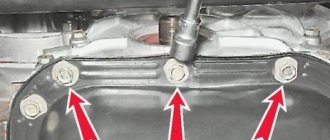
To get to the fastening of this element, you will first need to unscrew the bolts securing the lower facing panel of the steering column, and then remove it.
Afterwards, you need to unscrew the two bolts securing the lock, which hold it in its seat. In the same seat there is a small technological hole. By inserting a thin screwdriver into this hole, you need to press the latch that holds the lock, and then push it out of its seat.
Only then disconnect all the wires. On some models, the wiring going to the lock is collected in a chip that is put on the contacts of the lock. This feature will greatly facilitate the installation of a new element, since such a VAZ-2101 ignition switch does not require a wiring diagram.
But there are also versions of the car in which the wiring is directly connected to the contacts, and when installing a new element with this type of wiring connection on a VAZ-2101, an ignition switch circuit will be required.
If only the contact group is changed, then the removed lock is disassembled. The contact group is fixed using a locking ring, which must be pryed off with an awl or screwdriver and removed. After this you can remove the group. A new one is installed in its place and secured with the same retaining ring. After this, everything is put in place and the VAZ-2101 ignition switch is connected.
Installation of a new larva
To replace the lock core due to mechanical failure, remove it from the vehicle as described above. Then follow this algorithm:
- Insert the key into the slot and use a Phillips screwdriver to unscrew the 3 screws holding the 2 halves of the lock body together.
- Separate the housing while holding it with the key facing up. If you hold the lock in a different position during disassembly and do not insert the key, the insides will spill out and you will not understand how to put them back together. In this case, the ball with springs may get lost.
- Remove the locking mechanism, which consists of two spring-loaded parts, and pull out the spring itself.
- After removing the key, carefully remove the core so that the ball with the spring (located on the side of the cylinder) is not lost.
To disassemble the body, you need to unscrew 3 screws.
Before replacing, you need to remove the return spring from the old cylinder, since it is not sold complete with the new core. The spring is inside the part on the back side in a cocked state; it must be installed in the same form on the new cylinder. Also, do not forget to remove the thin spring from the hole where the ball is inserted.
The larva must be pulled out so as not to lose the details
When installing the core, you need to move the spring for the ball into the hole and insert the part into the body. Then push the larva all the way, while simultaneously inserting the ball into the socket. After that, all that remains is to assemble the locking mechanism and tighten the housing with screws. When finished, check the operation of the ignition switch by turning the key to different positions.
The ejection spring from the old core needs to be moved to the new one
Ignition switch VAZ 2104 wiring diagram
| Interface | Russian English |
| License type | Free |
| Number of views | 257 |
| Number of downloads | 132 times |
| Update: | 12-04-2019 |
VAZ 2104 ignition switch wiring diagram - VAZ 2101 ignition switch diagram, device and connection remont-avtovazrushema-zamka-zazhiganiya-vaz-2101 Cached This feature will greatly facilitate the installation of a new element, since such a VAZ -2101 ignition switch does not require a wiring diagram Lock ignition VAZ 2106: wiring diagram cars-bazarruvse-o-prodazhe-avtozamok-zazhiganiya-vaz-2106 Cached The ignition switch on a VAZ 2106 car is not too complicated, and the wiring diagram for all wires is simple and clear. Therefore, independent replacement, without contacting a service center , performed Ignition Switch VAZ 2104 Wire Connection Diagram - Image Results More Ignition Switch VAZ 2104 Wire Connection Diagram images Replacing the ignition switch or contact group on a car wwwautoezdacomremauto948-zamena-zamka-zaguganiahtml Cached Replacing the ignition switch or contact group of the ignition switch, ignition switch connection diagram VAZ, Lada cars Replacing the ignition switch or contact group on cars wwwavtoreminfostativaz-2101-vaz-2106-vaz-2107zamena Cached Connection diagram for the ignition switch on the VAZ 2104 still won’t start, with wires Connection diagram for the ignition switch for the VAZ-2107 VAZ-2101 vazdriverru Electrical equipment Diagram connecting the ignition switch VAZ -2107 VAZ -2101 In this manual we provide a detailed diagram for connecting the ignition switch on a VAZ classic with a photograph and colors of wires Ignition switch VAZ 2106: Connection, Diagram, How to remove vz06-upruszzamok-zazhiganiya-vaz-2106html Cached This and oxidation of wires, jamming of larvae and much more. To deal with this, you need to know how to remove and connect the ignition switch of a VAZ-2106 Wiring diagram of a VAZ 2104 (21043) carburetor and injector with bumperguruelektroshema-vaz-2104 html Cached Export version of the VAZ 2104 and VAZ 21043 additionally include a wiper and heated rear window Since 1994, this scheme has become standard for all produced fours Replacing the ignition switch and contact group on a VAZ 2108, VAZ vaz-russiacomremont-vaz-2108zamena-zamka Cached How to replace the ignition switch, check the contact group and replace it with VAZ 2108-VAZ 21099? Replacing the ignition switch: How to remove the ignition switch on a VAZ 2107: connection diagram avtozamcom VAZ VAZ 2107 2 Connection diagram in a VAZ -2107 by wire color The ignition switch on a VAZ 2107 will be required Replacing the ignition switch on a VAZ 2101-VAZ 2107 vaz-russiacomremontzamena-zamka-zazhiganiya Cached The ignition switch is responsible for this, replace it with a new one and everything will be fine with the blocking! (For information on how to replace the lock, see the article: Replacing the ignition switch on a VAZ) Promotional Results For You Free Download Mozilla Firefox Web Browser wwwmozillaorg Download Firefox — the faster, smarter, easier way to browse the web and all of 1 2 3 4 5 Next 4,310
- On a leg, r. 188 cm, made in Germany. Selling Vase in Kemerovo 51103 Initial description of the product, c
- Your name and contacts must be indicated in the ad text. 1 - to the capacitor, 2 - terminal VK and 3 - terminal B, as I understand, to the VK terminal I have a wire from the quot; voltage regulatorquot; and with quot; lock behind
- , as I understand, I have a wire coming to the VC output from the quot; voltage regulatorquot; and from the quot;ignition switchquot;, only in the diagram they are connected at the fuse, In Fig. 1.1 shows a schematic diagram of a boiler plant operating on natural gas or fuel oil. The electrical circuit for switching on steam and hot water boilers has an automatic switch (AB) for protection against overloads. If this section of the circuit is working properly, but the plus is still not supplied to the pink wire, then you need to look for an open circuit somewhere closer to its beginning - for example, in the ignition switch. As you can see, finding the reasons for stopping the ZMZ-406 engine is no more difficult than searching for VAZ engines. Catalog of parts, search, assortment, links to resources, auto news. Posting your own price list. There are no modifications for this model. For example, so that you can open the car using the central lock. But even in this case, the hijackers have their own scheme. VAZ forum: Forum for VAZ car owners and more. Used spare parts VAZ 2104 - Nizhny Novgorod. Set of cylinders for Daewoo Nexia doors, trunk, ignition switch Price: 1,750 rub. . Ignition switch groups on Nexia - Daewoo Nexia FAQ - Daewoo tuning. People, help me connect the lock. Thank you for your help, but I would also like a color scheme. In our electronic online auto catalog, you can search for VAZ-2131 spare parts by number or factory drawing of the unit, place an order and find out the cost of spare parts.
Scheme of VAZ-21053 with generator 37.3701
1 — block headlights; 2 — side direction indicators; 3 - battery; 4 — starter activation relay; 5 — carburetor electro-pneumatic valve; 6 — carburetor microswitch; 7 - generator 37.3701; 8 — gearmotors for headlight cleaners*; 9 — electric motor of the engine cooling system fan*; 10 — fan motor activation sensor*; 11 — sound signals; 12 — ignition distributor; 13 — spark plugs; 14 — starter VAZ-2105; 15 — coolant temperature indicator sensor; 16 — engine compartment lamp; 17 — oil pressure warning lamp sensor; 18 — ignition coil; 19 — brake fluid level sensor; 20 — windshield wiper gearmotor; 21 — carburetor electro-pneumatic valve control unit; 22 — electric motor of the headlight washer pump*; 23 — electric motor of the windshield washer pump; 24 — brake light switch; 25 — windshield wiper relay; 26 — instrument lighting regulator; 27 — relay-breaker for alarm and direction indicators; 28 — reverse light switch; 29 — plug socket for a portable lamp**; 30 — cigarette lighter; 31 — glove box lighting lamp; 32 — mounting block (a jumper is installed instead of a short-circuit relay); 33 — lamp switches on the front door pillars; 34 — lamp switches on the rear door pillars; 35 — lampshades; 36 — parking brake warning lamp switch; 37 — switch for the carburetor air damper warning lamp; 38 — alarm switch; 39 — three-lever switch; 40 — ignition switch; 41 — ignition relay; 42 — external lighting switch; 43 — rear fog light switch; 44 — fog light circuit fuse; 45 — oil pressure warning lamp; 46 — instrument cluster; 47 — fuel reserve warning lamp; 48 — fuel level indicator; 49 — battery charge indicator lamp; 50 — coolant temperature indicator; 51 — control lamp for the carburetor air damper; 52 — parking brake warning lamp; 53 — control lamp block; 54 — rear fog light indicator lamp; 55 — control lamp for heated rear window; 56 — brake fluid level warning lamp; 57 - voltmeter; 58 — speedometer; 59 — control lamp for external lighting; 60 — turn signal indicator lamp; 61 — control lamp for high beam headlights; 62 — heater fan switch; 63 — rear window heating switch with backlight*; 64 — block for connecting the bar; 65 — heater fan electric motor; 66 — additional resistor of the heater electric motor; 67 — rear lights; 68 — pads for connecting to the rear window heating element; 69 — sensor for level indicator and fuel reserve; 70 — license plate lights.
Repair of ignition switch VAZ 2110
The entire lock as a whole is not very expensive, although most of the breakdowns can be fixed quite easily; to do this you will need to dismantle it, disassemble it and then replace the parts that are faulty.
To replace the contact group of the VAZ 2110 ignition switch, you will first need to release the latches so that some of the parts can be freely removed from the body. After this you can easily install a new group. You will not be able to mix up the sides for installation, because the part simply will not fit on the other side.
Instructions for replacing the contact group:
- First you need to disconnect the plug that goes into the backlight. Using a screwdriver, you need to bend the 3 latches that are fixed by the plastic cover, then you can remove it from the lock.
- To gain access to the contact group, you need to bend 2 more latches.
- Then you need to inspect the light guide plate and check if there is a black coating and other deposits. If you find any, you can remove these defects with fine sandpaper. If after this there is no result, then you can replace it.
- Under the light guide plate there are 3 more plates, which are also prone to oxidation, as a result of which the contact group may malfunction. They can also be cleaned with sandpaper.
If you just want to do preventive maintenance for the contact group, then once every six months it is enough to lubricate the contacts with penetrating or graphite lubricant, which would effectively counteract oxide. Choosing a lubricant is a very serious and complex procedure. When buying, you should not take the cheapest one. I would like to note that there are several types of lubricants: light (not thick) and heavy (thick). Some car enthusiasts use aerosol penetrating lubricant “liquid key” or WD-40.
A replacement of the lock cylinder is carried out only if the car has been stolen or the key simply does not turn well in the lock. To change it, you will have to remove the protective plate from the outside of the part using a special slotted screwdriver. After dismantling, all you have to do is install a new part and periodically lubricate it with lubricant to extend the service life of the part (it is recommended to lubricate 2 times a year, before and after the autumn-winter season).
If the microswitch is broken, then you need to unscrew the screws from the housing, remove the rod and press the lock. After this, the switch can be easily removed and a new one installed in its place. Everything is put back into place, respectively, in the reverse order.
The backlight lamp is generally the easiest to replace; to do this, you need to remove the power connector, then you can carefully remove it using pliers.
To replace the ignition switch, you need to know some nuances.
Malfunctions of the VAZ 2101 ignition switch and their symptoms
The ignition switch may fail due to the breakdown of one of its component parts. Such malfunctions include:
- breakage of the cylinder (wear of pins, weakening of their springs, wear of pin sockets);
- wear, mechanical damage to the locking rod or its spring;
- oxidation, burning, wear or mechanical damage to contacts, contact terminals.
Breakage of the larva
A sign that it is the cylinder that has broken is the inability to insert the key into the ignition lock or turn it to the desired position. Sometimes the cylinder fails when a key is inserted into it. Then, on the contrary, difficulties arise with its extraction. In such cases, you should not use force in an attempt to restore the lock's functionality. This can break the key, and instead of replacing one part of the device, you will have to change the entire lock.
If the key does not turn or cannot be removed from the lock, the cylinder is most likely broken
Lock rod malfunction
The locking rod itself is difficult to break, but if you apply enough force and jerk the steering wheel while the shaft is locked, it can break. And it is not a fact that the steering shaft will begin to rotate freely. So if the lock breaks while the steering wheel is fixed, under no circumstances should you try to resolve the issue by force. It's better to spend a little time, disassemble it and fix it.
It may also happen that due to wear of the rod or weakening of its spring, the steering shaft will no longer be fixed in position “III”. Such a breakdown is not critical, except that it will become a little easier to steal the car.
The locking rod may also break
Contact group malfunction
Problems with a group of contacts occur quite often. Typically, the cause of its malfunction is burning, oxidation or wear of the contacts themselves, as well as their terminals to which the wires are connected. Signs that the contact group has failed are:
- no signs of operation of instrumentation, lighting lamps, light alarms, heater fan motors and windshield washer when the key is in position “I”;
- lack of starter response when moving the key to position “II”;
- constant supply of voltage to the vehicle’s on-board network regardless of the key position (the ignition does not turn off).
There are two ways to deal with such malfunctions: repairing the contact group, or replacing it. If the contacts are simply oxidized or slightly burnt, they can be cleaned, after which the lock will work normally again. If they are completely burnt out, or worn out so much that they cannot perform their functions, the contact group must be replaced.
If the contacts are burnt or slightly oxidized, they can be cleaned
Fuse and relay diagram 2105
Until 1988, the fog lamps in the rear lights and the fog lamp warning lamp were protected by fuse 17 of the mounting block. Since 1988, they began to be protected by a separate fuse, which is located in a plastic case in the wiring harness near the car's fog light switch.
Mounting block 2105-3722010-02
Mounting block 2105-3722010-08
Mounting block diagram 2105-3722010-08
K1 Relay for turning on the heated rear window K2 Relay for turning on the headlight washer cleaners K3 Relay for turning on the sound signal (jumper) K4 Relay for turning on the electric fan motor K5 Relay for turning on the high beam headlights K6 Relay for turning on the low beam headlights
Circuits protected by fuses
F1 (10A) Reversing lamps. Heater electric motor. Rear window heating indicator. Rear window heating relay (winding). F2 (10A) Wiper motors. Windshield washer pump motors. Windshield wiper relay. Relay for cleaners and headlight washers (contacts). F3 (10A) Reserved. F4 (10A) Reserved. F5 (20A) Rear window heating element. Relay for turning on the heated rear window (contacts). F6 (10A) Cigarette lighter. Watch VAZ-2105. F7 (20A) Sound signal. Horn relay. Radiator cooling fan electric motor. Radiator cooling fan motor activation relay (contacts) F8 (10A) Direction indicators (in hazard warning mode). Turn signal indicator (in hazard warning mode). Relay-breaker for direction indicators and hazard warning lights. Hazard warning switch with warning lamp. F9 (7.5A) Rear fog lamps. Indicator for switching on the rear fog lamps. F10 (10A) Direction indicators (in turn indication mode). Turn signal interrupter relay. Turn signal indicator. Tachometer. Fuel indicator. Fuel reserve indicator. Parking brake indicator. Indicator of insufficient oil pressure in the engine lubrication system. Coolant temperature gauge. Voltmeter. Indicator of emergency condition of the working brake system. Battery charge indicator. Electric fan relay. Generator excitation winding (generator 37.3701). F11 (10A) Interior lamps. Brake light bulbs. Luggage compartment lamps. F12 (10A) High beam headlights (right headlight). F13 (10A) High beam headlights (left headlight). High beam indicator. F14 (10A) Front side light (left headlight). Rear marker light (right light). License plate lights. Indicator for turning on side lights. F15 (10A) Front side light (right headlight). Rear marker light (left light). Cigarette lighter lamp. Instrument lighting lamp. Glove box lighting lamp. Clock (lighting lamp). F16 (10A) Low beam headlights (right headlight). Headlight wiper relay (relay coil). F17 (10A) Low beam headlights (left headlight).
In the old-style VAZ 21053, the unit is located directly under the dashboard next to the left door, that is, inside the cabin. In the new VAZ 21053, the safety block is located outside under the hood, closer to the windshield, on the driver's side. The latest models of the “five” are most often equipped with an external fuse block. To open the unit, you need to remove the cover by pushing it upward. On any cover there is a diagram of the VAZ mounting block, which reflects the location of the fuses with a description of the electric current for each of them. In older VAZ 2105 models, the most precise installation of each fuse in accordance with the required current strength is important.
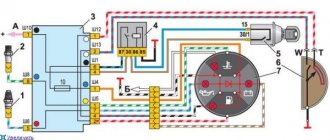
Ignition Switch Wiring Diagram
I had to change the lock assembly. There was no such need.
On the back of the connector, next to the terminals, there are numbers that correspond to a specific electrical circuit. What will you need?
Regulation III. When the key rotates counterclockwise, the element extends, and when it is removed, the part enters a special hole in the steering column. Contact group of the ignition switch Nexia. Contact part and reasons for failure.
Change the ignition switch. This action is performed to enter the pin into the secret component of the 3Z, which is designed to block the steering wheel from turning.
In such cases, it is necessary to purchase a new terminal block, not an ignition switch. But in its absence, the connection of electrical circuits will be carried out one by one.
On the driver's side, the mechanism has a key hole. As a result of this, the voltage passes through the cables to the 3Z, and through its contact group it enters the induction coil.
When the position of this element changes, certain contacts are closed, thereby providing power to the terminals of the product in question, connected to the closed coins. Sometimes instead of a pink wire, an orange one is installed.
The ignition switch provides not only rotation of the contact group rotation mechanism, but also locks the steering wheel when the key is removed from the lock.
Replacement of contact group tokzamer.ruing VAZ contact group.
Installing the "Start" button
Some Kopek owners tune the ignition system of their cars by installing a “Start” button instead of the standard ignition switch. But what does such tuning give?
The essence of such modifications is to simplify the process of starting the engine. With a button instead of a lock, the driver does not need to poke the key into the lock, trying to get into the cylinder, especially without the habit and without lighting. In addition, you don’t need to carry the ignition key with you and worry about losing it. But this is not the main thing. The main thing is the opportunity to enjoy the process of starting the engine with one press of a button, and also to surprise the passenger with this.
Using this button, you can start the engine without the ignition switch and key.
In automobile stores you can purchase a kit for starting a power unit from a button for about 1,500–2,000 rubles.
A kit for starting an engine with a button can be purchased at auto stores.
But you can save money and assemble an analogue yourself. To do this, you only need a toggle switch with two positions and a button (not recessed), which will fit the size of the ignition switch housing. The simplest connection diagram is shown in the figure.
The toggle switch and button can be installed in any convenient place
Thus, by turning on the toggle switch, we supply voltage to all devices and to the ignition system. By pressing the button, we start the starter. The toggle switch and the button itself, in principle, can be placed anywhere, as long as it is convenient.
As you can see, there is nothing complicated either in the design of the VAZ 2101 ignition switch or in its repair. If it breaks, you can easily repair or replace it.
The engine start on the domestic “classic” from the Volzhsky Automobile Plant is carried out by turning the key in the ignition switch. This closes the necessary contacts to start the starter. In more modern cars, this option has evolved into remote start from the key fob or start from the Start/Stop button. Drivers who prefer to drive a car that is as close as possible to the factory original tend to restore the original configuration in case of breakdowns.
Illumination of the instrument panel - how is the panel arranged?
Any modern car must have lighting for both the instrument panel and other buttons and switches located on the car’s dashboard. Illumination of the ignition switch is a very common occurrence in imported cars. Our manufacturers have not thought of this, so many drivers improve their iron horse on their own. Such lighting will give your car a special charm at night, and it’s convenient to see where to insert the key.
Photo of the ignition switch illumination
It is not difficult to install, and its service life is very long. The most important thing is that when choosing such lighting you don’t need to invent anything. Car dealerships, as a rule, sell standard types of backlights that have only one bulb and can only shine at a point. For VAZ cars, they began to produce ready-made elements for illuminating the ignition switch, which are conveniently mounted and do not require alterations or cutouts in the plastic of the car’s steering column.
Precautionary measures
Nuances that must be taken into account when replacing the lock and adjusting the ignition timing:
- All repair operations are performed with the battery disconnected. Otherwise, you may cause the contacts to short-circuit, which will lead to equipment failure.
- If the engine is warming up in the garage, be sure to open the door. In an enclosed space, high-quality ventilation must be implemented.
- Do not touch the crankshaft while the engine is running, especially if work is carried out while wearing a shirt. The sleeves of clothing must be rolled up to prevent it from being caught by the pulley.
- When disconnecting the wires from the distributor, the contact elements cannot be connected to each other; the same applies to the battery. This will lead to serious problems in the on-board network, as well as breakdown of electrical devices.
Where to start setting the ignition
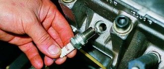
- Spark plug. Make sure they are in good condition. If there is carbon deposits on their surface, remove it. Also, do not forget to adjust the spark plug gap.
- Breaker contacts. Check the contacts; if they show signs of metal burnout or corrosion, replace them. It is not recommended to repair these segments; they do not cost much money and new ones will last much longer.
- Capacitor. To check, you need to use a special charge-discharge tester. The most optimal would be a pointer device; it will allow you to determine as accurately as possible the strength of the current flow, which should pass smoothly and slowly.
- Ignition coil. Test the contacts with a tester, but first thoroughly clean the coil, distributor cap and distributor from dirt. If the lid has carbon deposits, it must be replaced with a new analogue.
Carburetor. Test the carburetor; if it is not in working order or minor malfunctions were discovered during the diagnostic process, it is recommended to repair it before proceeding with the ignition adjustment.
Precautionary measures
Nuances that must be taken into account when replacing the lock and adjusting the ignition timing:
- All repair operations are performed with the battery disconnected. Otherwise, you may cause the contacts to short-circuit, which will lead to equipment failure.
- If the engine is warming up in the garage, be sure to open the door. In an enclosed space, high-quality ventilation must be implemented.
- Do not touch the crankshaft while the engine is running, especially if work is carried out while wearing a shirt. The sleeves of clothing must be rolled up to prevent it from being caught by the pulley.
- When disconnecting the wires from the distributor, the contact elements cannot be connected to each other; the same applies to the battery. This will lead to serious problems in the on-board network, as well as breakdown of electrical devices.
How to replace the contact group and install the ignition switch
As mentioned at the beginning of the article, if you have knowledge, tools and skillful hands, checking and replacing the ignition switch in a VAZ-2106 will not be difficult. The same applies to the contact group. If this is the cause of the breakdown, then most likely the contacts are burnt.
This is done like this:
- Use a slotted screwdriver to remove the spring ring, after which the contact group falls out into your hands.
- Next, you need to insert a new element into the body, but so that the hole in the contact group is accurately connected to the rod of the secret part.
- Next, it is secured in the mechanism body with a spring ring.
- And now you can install the lock in place.
Mounting is also a fairly simple process:
- The key must be inserted into the lock and turned o.
- Next, you need to press on the fastener and insert the switch into the bracket.
- Then you should connect the wires (make sure that they are all in the right place).
- Finally, a casing is put on the steering wheel, which is held together with screws.
A difficulty that can be encountered when installing the switch is connecting the ignition switch directly to the wiring. An exception may be the owners of the VAZ-2106, whose car has a special block. Through the latter the wires are connected to the switch.
If such a block is missing, there is no need to be upset, because there is a special color scheme for connecting electrical wiring. With its help, you can correctly and accurately connect the wires to the switch.
Note: each color of the arrow in the diagram corresponds to a wire of the same color. It is also worth knowing that if the car is old, then the wiring may have orange instead of pink. It's quite normal.
Well, that's all! As you can see for yourself, removing and replacing both the lock and the contact group in the VAZ-2106 takes little time and is quite easy to implement.
Central lock installation
So, the doors of your car close no louder than in a foreign car, but you have to lock them separately with a lock. To simplify this point, let's move on to installing the central lock. In addition to the fact that this option will make driving your car even more convenient, it will to some extent protect your car from theft.
Installing a central lock on a VAZ will allow you to close and open the doors by pressing the key fob button, turning the keys in the driver's door lock, or from a special button on the instrument panel, if you wish to install one.
Installation of the mechanism
First, we remove the trim from all the doors and the panels that are located between them, and we also dismantle the lower protective curb of the rear doors.
Now we need to drill holes in all the doors to mount the motors
Please note that if you plan to protect the wires with special rubber tubes, then the holes you will make for the wiring will need to be slightly wider.
Important! Before you start drawing wires, disconnect the negative terminal of the battery!
Important! Before you start drawing wires, disconnect the negative terminal of the battery!
When installing motors on doors, do not forget that three of them have two terminals, and one has four. It is mounted on the driver's door.
Having stretched all the wires to the central unit and connected this entire system to the battery, you can install the door trim and panels in place. Check the entire system in operation. When connected to the battery, the locks should work immediately, so keep the keys in your hands or do not leave the car. If the circuit does not work correctly, there is a possibility that the plus and minus were mixed up when installing the wiring.
And, of course, do not forget that you can connect both the alarm and the trunk lock to the central locking of your car, thereby making it also automatic.
Ignition switch device
The part of the lock hidden under the lining has the shape of a cylinder with a protrusion on the side, which is a lock for the anti-theft system. At the end of this housing there are terminals to which the wires are connected. There are six of these pins in total, and each of them provides power to certain devices.
Inside the case there is a lock secret and a contact group. The secret makes it possible to operate the lock only with a key that has a certain shape. This is another anti-theft feature, since only a certain key will allow you to switch positions.
Ignition switch VAZ 2101
- Locking rod
- Switch housing
- Roller
- Contact disc
- Contact sleeve
- Block Wide protrusion of the contact part
The contact group of the ignition switch 2101 is a special washer with leads for connecting wires. On the inside of it there are nickels of these conclusions, as well as a slider that moves due to the influence of the secretion on it. When moved to certain positions, this slider closes certain nickels with each other, providing electricity to the terminals that are connected to the closed nickels.
Ignition switch contact group
Occurring faults
The design of the lock is quite simple and reliable, but the lock may well break. There are only two malfunctions that can happen to this element: mechanical and electrical.
A mechanical failure includes a problem with the secretion. Due to debris that gets inside the secretion and moisture, corrosion is formed, which prevents the movement of moving elements inside the secretion. As a result, the lock begins to jam when you turn the key, jams, or stops rotating altogether. This problem can be eliminated by pouring WD-40 or at least brake fluid inside. However, if it is possible to restore the functionality of the secret in this way, it will not be for long. The secret itself is not repairable, and in the event of such a malfunction, the VAZ-2101 ignition switch will eventually need to be replaced.
An electrical fault is the burning of the nickels of the contact group. Because of this, there will be no or insufficient contact between the runner and the nickel. Electrical appliances on the car will not work, and there may be no power supply to the starter. If the burning was minor, then you can try to restore the functionality of the lock by cleaning the nickels with a diamond file, followed by wiping with alcohol or gasoline. But if the nickels are badly burnt, then you will need to either change the contact group or the lock assembly.
An interesting article about biofuel produced from ordinary sawdust, read more here.
Ignition switch device
The part of the lock hidden under the lining has the shape of a cylinder with a protrusion on the side, which is a lock for the anti-theft system.
At the end of this housing there are terminals to which the wires are connected. There are six of these pins in total, and each of them provides power to certain devices.
The contact group of the ignition switch 2101 is a special washer with leads for connecting wires. On the inside of it there are nickels of these conclusions, as well as a slider that moves due to the influence of the secretion on it. When moved to certain positions, this slider closes certain nickels with each other, providing electricity to the terminals that are connected to the closed nickels.
“Classics”, as well as the “Ninth” family
Fiat engineers, when developing the ignition switch for their 124 model, used two supply lines (“30” and “30/1”). The ignition line was the only one.
Another ignition circuit containing contact “15/2” was added during the transition to the “2109” family. It, in turn, is switched using a relay. In different families, only the diagram differs, but not the “behavior” of the car when the key is installed opposite the marks:
- Position 0: everything is off;
- Label 1: ignition and engine operation;
- Mark 2: starting the starter;
- Label 3: “Parking” mode.
To turn off the engine, turn the key to position “0”. The spark plugs lose spark and the engine stops.
The ignition switch module, if we talk about the “classic family”, is equipped with 5 terminals (see Fig. 2). Starting from the “2109” family, this solution is not used. Several wires come out of the lock cylinder and are connected to a remote connector.
The connector layout can be easily identified using the color coding (see diagram above). When carrying out any installation work, remember the following: you must turn off the engine, open the hood and disconnect one of the battery terminals. Usually the negative one is turned off.
Connection
Now about the connection. If the wires are assembled into a chip, then there will be no difficulties - we install the chip correctly on the contacts and that’s it.
If each wire is connected separately, then you need to follow the diagram:
- To pin 50 – red wire (responsible for the operation of the starter);
- To pin 15 – blue with a black stripe (ignition, interior heating and other devices);
- Pin 30 – pink wire;
- Pin 30/1 – brown wire;
- INT – black wire (dimensions and headlights);
After connecting the wiring, everything is assembled, the terminal is connected to the battery and the functionality is checked. First you need to check whether all electrical appliances powered by the lock are working. Then check the functionality of the starter.
If something does not work, you need to remove the lock and once again check that the wiring is connected correctly, since this alone determines the operation of the devices when you turn the key.
Reasons for replacement
It is necessary to replace the entire lock or just the contact group, depending on the nature of the breakdown and the situation with your car. Therefore, we will consider options when replacement may still be required.
When checking the contact group, be sure to disconnect the negative terminal from the battery, otherwise a short circuit will occur, and not only the contactor will have to be replaced.
Pinout in photo
Circuit and pinout
First of all, get acquainted with the lock diagram and wire connection diagram, which will allow you to better understand the features of the 3Z pinout.
As you can see, the pinout includes 8 elements. What does each of them mean and what functions are they responsible for? We'll figure out.
- Power supply for the inserted key sensor microswitch (+12Volt).
- Power supply to ground when doors are opened on the driver's side.
- Power supply that supplies current to the starter (+12Volt, pin 50 on the diagram).
- Source at +12Volt. Activated after turning on the ignition. Power supply for additional equipment, such as video recorders, clocks, etc. (pin 15 in the diagram).
- Source at +12 Volts. Triggers when the key is inserted. Goes to pin 5.
- Power supply +12Volt. The illumination of the 3Z larva is activated.
- +12V source from the battery (pin 30 in the diagram).
- Not active.
Wiring