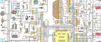
The VAZ-2106 car was produced from 1976 to 2008. This guide provides color-coded wiring diagrams (for the injector and carburetor) with a description of all elements for various modifications. The information is intended for self-repair of the six. Electrical circuits are divided into several blocks for ease of viewing via a computer or phone; there are also circuits in the form of a single picture with a description of each element - for printing on a printer. All electrical equipment of a car can be divided into the following components:
- engine starting system;
- battery charge elements;
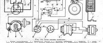
- fuel mixture ignition system;
- elements of external and interior lighting;
- sensor system on the instrument panel;
- sound notification elements;
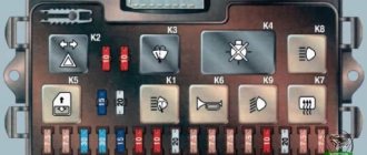
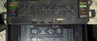
- fuse block.
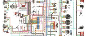
Electrical circuit diagram (1988-2001)
Content
- Front lights;
- Side direction indicators;
- Accumulator battery;
- Battery charge indicator lamp relay;
- Relay for low beam headlights;
- Headlight high beam relay;
- Starter;
- Generator;
- Exterior lights;
- Interior lights;
- Fan motor activation sensor;
- Engine cooling fan electric motor;
- Sound signal;
- Ignition coil;
- Distributor;
- Spark plug;
- Carburetor solenoid valve;
- Coolant temperature indicator sensor;
- Engine compartment lamp;
- Reversing light switch;
- Oil pressure indicator sensor;
- Low oil pressure indicator sensor;
- Insufficient brake fluid level indicator sensor;
- Windshield wiper motor;
- Switch*;
- Windshield washer motor;
- Fan motor activation relay**;
- Voltage regulator;
- Windshield wiper relay;
- Additional fuse box;
- Main fuse box;
- Relay-breaker for hazard warning lights and direction indicators;
- Relay for turning on the heated rear window***;
- Brake light switch;
- Socket for portable lamp****;
- Additional resistor for heater motor;
- Heater motor;
- Heater motor switch;
- Watch;
- Glove compartment lamp;
- Cigarette lighter;
- Hazard switch;
- Instrument lighting regulator;
- Brake fluid level indicator lamp;
- Three-lever switch;
- Ignition switch;
- Rear window heating switch***;
- Rear fog lamp switch;
- External lighting switch;
- Lamp switches located in the front door pillars;
- Motor reducers for electric windows of front doors***;
- Lamp switches located in the rear door pillars;
- Parking brake warning lamp switch;
- Interior lighting lamps;
- Fuel level indicator with reserve indicator;
- Coolant temperature gauge;
- Oil pressure gauge with low pressure indicator;
- Tachometer;
- Parking brake warning lamp;
- Battery charge indicator lamp;
- Carburetor air damper indicator lamp;
- Side light indicator lamp;
- Turn signal lamp;
- Headlight high beam indicator lamp;
- Speedometer;
- Carburetor choke warning switch;
- Left front door power window switch***;
- Front door power window activation relay***;
- Right front door power window switch***;
- Tail lights;
- License plate lights;
- Level indicator and fuel reserve sensor;
- Pads connected to the rear window heating element***;
- Trunk light;
- Rear fog lamp.
The order of conditional numbering of plugs in blocks:
A
- Switch;
b
— Ignition distributor sensor;
V
— Windshield wiper and windshield wiper breaker relay;
G
— Hazard warning and direction indicator breaker relay;
d
— Three-lever switch.* Installed if a vehicle uses a contactless ignition system. In this case, an ignition distributor sensor of type 38.3706 and an ignition coil of type 27.3705 or 027.3705 must be installed.
** Since 2000, the electric motor 12 has not been installed and is switched on directly by sensor-switch 11. In this case, instead of the previously used temperature sensor 11 of type TM-108, sensor-switch 661.3710 is used.
*** Installed on car parts.
**** Not installed since 2000.
Modifications of the VAZ-2106 car
VAZ-21060 . Modification with the symbol VAZ-21060, Izhevsk assembly of recent years of production with a VAZ-21067 injection engine with a catalyst that meets the Euro-2 environmental standard
VAZ-21061 . Modification with a VAZ-2103 engine, some cars with a similar index were equipped with a simplified engine cooling system and did not have an electric fan. Instead, an impeller was installed on the end of the coolant pump shaft. Already Russian cars were equipped with bumpers from the VAZ-2105, some examples were equipped with cleaners and headlight washers.
VAZ-21062 . Export, right-handed modification of the base six.
VAZ-21063 . A car with an improved VAZ-21011 engine, with an oil pressure sensor and an electric engine cooling fan. The release of this modification was completed in 1994.
VAZ-21064 . Export, right-handed modification, like the VAZ-21062, but the VAZ-21061 modification was taken as the basis
VAZ-21065 . A modification of the car with improved equipment, which was produced from 1990 to 2001. An engine with a volume of 1569 cm3 was installed as a power unit. Other differences from the base model include a more powerful generator, a 5-speed gearbox, a rear axle gearbox with a gear ratio of 3.9, a contactless ignition system, and a Solex carburetor. There were other changes both in the exterior and in the interior, in general it was a “luxury” version of the VAZ-2106 sedan.
VAZ-21065-01. The same VAZ-21065 but with a VAZ-2103 engine
VAZ-21066 . Export, right-hand drive modification of the VAZ-21063 car.
VAZ-21068 . A car that was produced as a carrier of units during the development period of the new VAZ-2108 and VAZ-21083 engines.
VAZ-21069 . Modification of the VAZ-2106 manufactured by order of the special services. It was equipped with a two-section rotary piston engine VAZ-411 with a power of 120 hp, VAZ-413 with a power of 140 hp.
Electrical diagram (1977-1987)
- Front lights;
- Side direction indicators;
- Accumulator battery;
- Battery charge indicator relay;
- Relay for low beam headlights;
- Headlight high beam relay;
- Starter;
- Generator;
- Exterior lights;
- Interior lights;
- Sound signals;
- Engine cooling fan electric motor;
- Fan motor activation sensor;
- Ignition coil;
- Distributor;
- Spark plug;
- Carburetor solenoid valve;
- Coolant temperature indicator sensor;
- Engine compartment lamp;
- Reversing light switch;
- Oil pressure indicator sensor;
- Low oil pressure indicator sensor;
- Insufficient brake fluid level indicator sensor;
- Windshield wiper motor;
- Windshield washer motor;
- Relay for turning on sound signals;
- Fan motor relay;
- Voltage regulator;
- Windshield wiper relay;
- Additional fuse box;
- Main fuse box;
- Relay-breaker for hazard warning lights and direction indicators;
- Brake light switch;
- Plug socket for portable lamp;
- Heater motor;
- Additional resistor for heater motor;
- Watch;
- Heater motor switch;
- Glove compartment lamp;
- Cigarette lighter;
- Hazard switch;
- Instrument lighting switch;
- Indicator lamp for insufficient brake fluid level;
- Three-lever switch;
- Ignition switch;
- Rear fog light switch*;
- External lighting switch;
- Lamp switches located in the front door pillars;
- Front door open alarm lamp switches;
- Front door open warning lamps;
- Lamp switches located in the rear door pillars;
- Parking brake warning switch;
- Interior lighting lamps;
- Fuel level indicator with reserve indicator;
- Coolant temperature gauge;
- Oil pressure gauge with low pressure indicator;
- Tachometer;
- Parking brake warning lamp;
- Battery charge indicator lamp;
- Carburetor air damper indicator lamp;
- Side light warning lamp;
- Turn signal lamp;
- Headlight high beam indicator lamp;
- Speedometer;
- Carburetor choke warning switch; 66 - p
- Parking brake warning relay;
- Tail lights;
- License plate lights;
- Level indicator and fuel reserve sensor;
- Trunk light;
- Rear fog lamp*. The order of conditional numbering of plugs in blocks:
a — Windshield wiper and windshield wiper breaker relay;b — Hazard warning and turn signal breaker relay;
c — Three-lever switch.
* Installed on parts of manufactured cars.
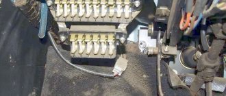
Underhood wiring
The main part of the electrical wiring is located in the engine compartment, where the main elements, electronic and mechanical sensors of the car are located. A significant number of wires reduce the overall aesthetic appearance of the motor, surrounded by multiple cables. For convenient maintenance of the mechanical components of the engine, the manufacturer places the wiring in a plastic braid, preventing it from rubbing against metal elements of the body and hiding it in body cavities out of sight so that it does not distract attention from the power unit.
Under the hood, electrical wiring provides connection to the main elements of the power unit
Under the hood, the engine contains many auxiliary elements that consume or generate electrical energy, such as a starter, generator, and sensors. All devices are connected to each other in a certain way and in the order shown on the electrical diagram. The wires are secured in a safe and inconspicuous place, which prevents them from wrapping around moving parts of the chassis and motor.
Grounding wires are located inside the engine compartment, a tight connection of which is only permissible on a smooth metal surface. A reliable grounding contact through the car body provides a single circuit of reverse current from the negative terminal of the battery, which is the “ground” of the vehicle. The bundled cables from the sensors are placed in a protective casing that provides insulation from heat, liquids and radio interference.
The wiring system located in the engine compartment includes:
- battery;
- starter;
- generator;
- ignition module;
- high-voltage wires and spark plugs;
- numerous sensors.
Engine fan diagram
- Electric motor activation sensor;
- Fan motor;
- Motor start relay;
- Main fuse box;
- Ignition switch;
- Additional fuse box;
- Generator;
- Accumulator battery.
Since 2000, a relay for turning on the cooling fan motor has not been installed, and the wires connected to the relay have been removed from the wiring harness. In addition, since 2000, the electric motor has been switched on by sensor type 661.3710. The temperature of closing the sensor contacts is (92±2.5) °C, and the opening temperature is (87±3) °C.
Typical malfunctions of the instrument panel
Deviation of the scale arrow indicates a malfunction of the device and damage to the wire that connects the sensor to the pointer.
The following malfunctions of the instrument panel elements are possible:
- the arrow on the scale of the coolant temperature sensor is constantly either in the initial position or in the red zone;
- the fuel gauge needle: does not leave the initial position even with a full tank, always lies at the end of the scale, moves jerkily and often returns to the beginning of the scale;
- The fuel reserve indicator light is constantly on or does not light up;
- The oil pressure indicator does not light up when the ignition is turned on, it lights up constantly, and goes out at high engine speeds;
- speedometer, tachometer faulty;
- The flexible speedometer drive is noisy.
Read more: Modification of the rear suspension of the Solaris
Device malfunctions are eliminated by replacing sensors, contacts, devices, and restoring wiring.
Low/high beam circuit
- Headlights;
- Fuse box;
- Speedometer with high beam headlight indicator;
- Relay for low beam headlights;
- Headlight switch;
- Headlight high beam relay;
- Generator;
- External lighting switch;
- Accumulator battery;
- Ignition switch.
Diagram of brake lights, reverse lights, side lights, license plate lighting
- Front lights with side light lamps;
- Accumulator battery;
- Generator;
- Engine compartment lamp;
- Fuse box;
- Brake light switch;
- Plug socket for portable lamp;
- Reversing light switch;
- Ignition switch;
- External lighting switch;
- Speedometer with side light indicator;
- Trunk light;
- Rear lights with parking lights, brake lights and reversing lights;
- License plate lights.
Hazard and turn signal diagram (1977-1985)
- Headlights with direction indicator lamps;
- Accumulator battery;
- Generator;
- Side direction indicators;
- Main fuse box;
- Additional fuse box;
- Ignition switch;
- Hazard switch;
- Turn signal switch;
- Relay-breaker for alarm and direction indicators (23.3747);
- Speedometer with turn signal indicator;
- Rear lights.
Hazard and turn signal diagram (1985-2001)
- Sidelights;
- Side direction indicators;
- Accumulator battery;
- Generator;
- Ignition switch;
- Main fuse box;
- Additional fuse box;
- Relay-breaker for hazard warning lights and direction indicators (231.3747);
- Turn signal warning light in the speedometer;
- Hazard switch;
- Tail lights;
- Turn signal switch in a three-lever switch.
LED panel lighting
The most popular lighting for VAZ 2106 devices is LEDs. The panel looks especially beautiful at night. LED lamps of various colors are used for illumination. At least 2 bulbs are installed on the speedometer and tachometer dials. For small sensors, one LED is sufficient.
LED lighting around the entire perimeter will look more impressive. LEDs must meet the 12-volt voltage of the on-board network. When installing LEDs, be sure to observe polarity. Thanks to tuning, the VAZ 2106 tidy takes on an individual look and becomes more convenient and functional.
Windshield wiper and washer diagram
- Washer motor;
- Windshield wiper and washer switch;
- Windshield wiper relay;
- Wiper motor;
- Fuse box;
- Ignition switch;
- Generator;
- Accumulator battery.
Since 1985, a reusable thermobimetallic fuse has been installed in the wiper motor. It is designed to protect the electric motor from overloads.
Sound signal circuit
- Sound signals;
- Relay for turning on sound signals;
- Sound switch;
- Fuse box;
- Generator;
- Accumulator battery.
Since 1993, one sound signal of type 20.2721-01 has been installed on cars, and it is turned on without an auxiliary relay “2”. There are two wires leading to the signal: red from plug “A” of the fuse box and gray with a black stripe from the horn switch.
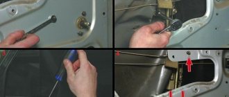
Dismantling instructions
Removing the VAZ 2106 instrument scale may be necessary when repairing and replacing its elements, tuning and modification. Dismantling is not difficult and will require a small set of tools: wrenches and screwdrivers.
Stages of dismantling the tidy
The removal procedure consists of the following steps:
- First of all, you need to remove the front box from below the tidy.
- Then you need to unscrew all the fasteners and pull out the lower latches.
- Remove the radio plate.
- Next, remove the casing from the steering column.
- The next step is to disconnect the wires. Each one needs to be marked to make assembly easier.
- Now you can dismantle the shield by disconnecting all connectors.
- After removing the sensors, they need to be sorted in order to assemble correctly.
After upgrading the instrument panel, assembly is carried out in the reverse order (the author of the video is Nikolay).
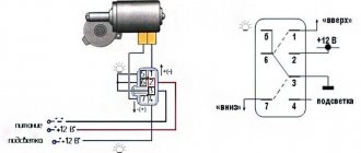
Window lifters
- Main fuse box;
- Power window relay;
- Left door power window switch;
- Right door power window switch;
- Right door electric window motor reducer;
- Left door electric window motor reducer;
- Additional fuse box;
- Ignition switch;
A - to terminal -30- of the generator;B - to the instrument lighting switch; B - conventional numbering of plugs in the gear motor block.
General tuning aspects
The simplest tuning of the VAZ 2106 dashboard is to purchase a ready-made set of accessories and replace standard devices. You can install it yourself using the instructions included with the kit. More labor-intensive is the tuning of individual devices, which involves replacing stickers and arrows.
When changing arrows and stickers, you need to be careful, as these parts are very fragile.
Tuning the VAZ instrument panel can be done by replacing the meter dials with white ones and installing overlays on the panel. You can cover the panel with artificial leather or leather if you have sufficient funds. Before stretching the material, the surface of the shield must be cleaned and then adhesive must be applied in an even layer. Next, press the leather or substitute over the entire surface and wait until the glue dries. At the last stage, you need to process the edges, giving it an aesthetic appearance.