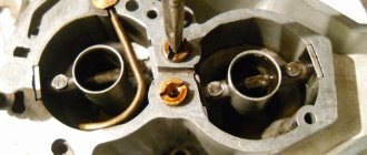
The simplest carburetor consists of two main parts: a mixture-forming device and a float chamber. In the mixture-forming device, a flammable mixture is prepared, and the float chamber is a reservoir from which fuel is supplied to be mixed with air.
The carburetor's mixture-forming device has an air inlet, a diffuser, a mixing chamber, a throttle valve, and an outlet. The outlet pipe usually ends in a flange that secures the carburetor to the engine intake manifold.
Promotional offers based on your interests:
A hose for supplying air or an air filter directly is installed on the inlet pipe. The diffuser is a local reduction in the cross-section of the mixture-forming device. Thanks to the diffuser, the conditions for fuel atomization are improved, since when the engine is running, the maximum air flow speed is created in the narrowest section of the diffuser. In this place, a sprayer is installed, which is a tube connected to a diffuser. Fuel flows out and atomizes through the atomizer.
The float chamber contains a float mechanism consisting of a float and a needle valve. The float is hinged to the wall of the float chamber. The shut-off needle of the needle valve rests on the float lever.
When fuel is supplied through the fitting into the float chamber, the float floats up and with its lever raises the shut-off needle, closing the needle valve. As soon as the fuel level in the float chamber reaches a predetermined limit, the needle valve will close completely and the flow of fuel into the chamber will stop. When fuel is consumed from the float chamber, the float lowers and opens the needle valve. Fuel begins to flow into the float chamber again until the specified level is reached. Thus, the float chamber, using a float mechanism, ensures that the specified fuel level is maintained under all engine operating modes.
The main jet is located at the bottom of the float chamber. Its main purpose is to dose fuel to obtain a combustible mixture of the desired composition. The jet is a plug with a central calibrated hole. The diameter of the calibrated nozzle hole is selected depending on the required fuel flow. The length of the calibrated hole of the nozzle, the angles of the inlet and outlet chamfers, and the diameters of the channels in the body of the nozzle are also of great importance for the formation of flammable mixtures. The main jet can be installed at the bottom or top of the sprayer.
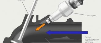
When the engine crankshaft rotates during the intake strokes and when the throttle valve is open, air flows through the carburetor mixing chamber. Inside the diffuser, the air flow speed increases significantly, and a vacuum is created at the sprayer outlet. In this case, due to the presence of the hole, the pressure in the float chamber remains equal to atmospheric pressure. Due to the pressure difference in the float chamber and in the atomizer, fuel begins to flow through the main jet and atomizer in the form of a fountain, ending up in the neck of the diffuser. Here, a stream of incoming air crushes the escaping fuel into small droplets, which mix with air, evaporate and form a combustible mixture.
The formation of a combustible mixture in the mixing chamber of the carburetor does not occur in full. Some of the fuel in the form of droplets does not have time to evaporate and mix with air. Unevaporated fuel droplets move in the air flow and settle on the walls of the mixing chamber and inlet pipeline. Fuel deposited on the walls forms a film that moves at low speed. To evaporate the fuel film, the intake manifold is heated when the engine is running. Most often, liquid heating (from the engine cooling system) or heating with exhaust gas heat is used. Thus, we can assume that the formation of a combustible mixture ends at the end of the engine intake pipe.
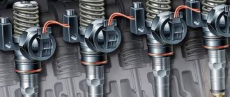
In this article you will learn about fuel injection systems. The carburetor is the very first mechanism that made it possible to combine gasoline with air in the required proportion to prepare an air-fuel mixture and supply it to the combustion chambers of the engine. These devices are actively used to this day - on motorcycles, chainsaws, lawn mowers, and so on. It’s just that they were long ago supplanted from the automotive industry by injection injection systems, which are more advanced and perfect.
A little history
Early developments at the dawn of the engine building era used lighting gas as fuel. At an early stage, such engines simply did not need a carburetor. The illuminating gas entered the cylinders due to the vacuum that was formed during engine operation. The main problem with such fuel was its high cost and a number of difficulties during use.
The second half of the 19th century was the period when inventors, engineers and mechanics all over the world tried to replace expensive lighting gas with a more economical, cheaper and accessible type of fuel for the internal combustion engine. The best solution was to use liquid fuel that is familiar to us today. It is worth considering that such fuel cannot ignite without the participation of air.
To prepare a mixture of air and fuel, an additional device was required. Not only that, but it was also necessary to mix air with fuel in the required proportions. To solve this problem, the first carburetor was invented. The device was released in 1876. The creator of an early model of the carburetor was the Italian inventor Luigi De Christoforis. In its design and operating principle, the first carburetor had a number of significant differences from more modern analogues.
The principle of operation and design of a simple carburetor
In the first device, invented by L. Christoforis in 1876, the fuel was heated, evaporated, and the resulting vapors and air flows were mixed. A year later, the solution was improved using the principle of fuel atomization, which became the basis for subsequent projects.
Before the widespread use of devices familiar to us, there were bubbling and membrane-needle models. The first were in the form of a gasoline tank, in which a board and a pair of pipes were located close to the surface for supplying a mixture of fuel and air from the atmosphere and taking it into the engine. The air moved under the board, directly above the fuel, became enriched in vapor and became a combustible mixture. It was a simple but working system. The throttle valve was located separately. The functioning of the motor with a bubbler unit was influenced by natural conditions - evaporation depended on temperature. Such a system was difficult to regulate and was explosive.
Diagram of a bubble carburetor.
The membrane-needle device is located separately from the gas tank. It contained several chambers, rigidly connected using a rod. The valve seat through which fuel was supplied was locked with a needle on the stem. The chambers were connected by a fuel channel and a mixing zone. The parameters of the device were determined by the springs on which the membranes were pressed. Such a carburetor worked regardless of street conditions and location; it was popular in the early 19th century, when it was installed on cars and motorcycles, and in airplanes with piston internal combustion engines.
Diagram of a membrane-needle carburetor.
What is a carburetor
The carburetor is the most important component among all vehicle systems. It refers to the design of an internal combustion engine and is designed to form a fuel-air mixture. Carburetion (that is, creation) of the mixture is carried out by mixing liquid fuel and air, and the proportionality of the parts is important.
Today, carburetors are used on a wide variety of engines to ensure the operation of a variety of technical devices. The first types of carburetors (bubble carburetors) are no longer used, as they have been replaced by more efficient membrane-needle and float carburetors.
A needle-membrane carburetor consists of chambers that are separated by special membranes. The membranes are quite rigidly fixed to each other by a rod, one of the ends of which is a needle. During carburetor operation, the needle moves up and down and either opens or closes the fuel supply valve. This is the simplest type of carburetor mechanisms today, which is used on lawn mowers, airplanes and some types of trucks (for example, ZIL-138).
The float carburetor is presented today in several modifications, but they all have a similar operating principle. The main element of such a device is a float and a float chamber. It is the chamber that is responsible for the timely supply of fuel and air; the air-fuel mixture is formed in it and supplied to the combustion chamber. The float carburetor guarantees smooth operation of the engine and provides good dynamics and traction. Therefore, this carburetor type of device has gained particular popularity in the modern automotive industry.
Carburetor and injector
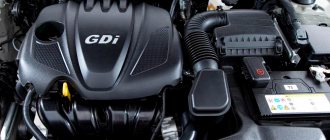
Further in the history of fuel supply and mixture formation systems, monoinjection (monoinjector) first appeared, and fully electronic injection and high-performance fuel injectors finally replaced obsolete carburetors.
The main advantage of the injector is much more accurate and timely dosing of fuel to obtain the required proportions of the fuel-air mixture. The emergence and introduction of affordable microprocessors into the auto industry ultimately led to the fact that the need for a complex carburetor and additional devices in its design simply disappeared. All the functions of the individual elements of the carburetor were taken over by one single control unit (ECU), and simple design devices were installed in the injector design.
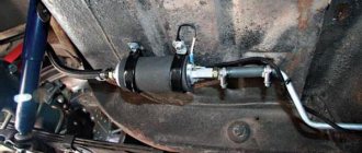
Today, carburetor injection is found only on those engines whose main purpose is the target installation on special equipment. The reason for this decision was the vulnerability of electronic injection systems during harsh operating conditions. Electronic components and injector modules suffer from increased humidity and contamination, and injectors are sensitive to fuel quality. As an example, it is worth saying that it is definitely better to install a mechanical carburetor on a special vehicle when using it in swamps, which will not burn out. Such a carburetor can always be easily maintained, cleaned and dried if necessary.
Types of carburetors
As we have already said, the process of modernizing carburetors has generated a large number of types of this device from different manufacturers. All this variety of carburetors can be divided into three groups:
- bubbling;
- membrane-needle-shaped;
- float;
The first two types of carburetors have practically not been seen for a long time, so we will not dwell on these designs. It is more advisable to consider a float carburetor, which can still be seen in various modifications on civilian cars of the 90s era today.
Float carburetor design
The main job of a carburetor is to mix fuel and air. Different models of carburetors carry out this process according to a similar principle. The float carburetor consists of the following elements:
- float chamber;
- float;
- float lock needle,
- jet;
- mixing chamber;
- spray;
- Venturi tube;
- throttle valve;
The float carburetor is designed in such a way that a special line is connected to its float chamber. This line supplies fuel from the fuel tank to the carburetor. Regulation of the amount of fuel in the chamber is carried out through two elements that are interconnected. We are talking about a float and a needle. A drop in the fuel level in the float chamber means that the float will drop along with the needle. Thus, it turns out that the lowered needle will open access for the next portion of fuel to enter the chamber. When the chamber is filled with gasoline, the float will rise, and the needle will simultaneously block access to fuel.
At the bottom of the float chamber there is the next element called a jet. The nozzle acts as a calibrator and ensures dosing of the fuel supply. Through the nozzle, fuel enters the atomizer. This is how the required amount of fuel moves from the float chamber to the mixing chamber. The process of preparing the working fuel-air mixture takes place in the mixing chamber.
Structurally, the mixing chamber has a diffuser. This element is designed to increase air flow speed. The diffuser is responsible for creating air vacuum in the immediate vicinity of the sprayer. This helps draw fuel out of the float chamber and also helps to atomize it better in the mixing chamber. This is the basic design of a simple float carburetor.
DESIGN AND PRINCIPLE OF OPERATION OF THE CARBURETOR
The float-type carburetor is a single unit included in the power system. During the use of such a system on cars, a large number of carburetors have been developed, with different design features, but they all function using the same principle.
The simplest float carburetor consists of two chambers:
The first task is to dose the fuel and maintain it at a certain level. Thanks to this chamber, a stable supply of gasoline is ensured under different engine operating conditions.
Structurally, it is very simple. Inside the assembly there is a cavity with a float placed in it, connected to a needle-type valve, which is located in the gasoline supply channel from the gasoline pump. As fuel is consumed, the float lowers, and with it the valve, as a result the channel opens and gasoline is pumped into the cavity. When the required level is pumped, the float together with the valve rises up and completely blocks the channel.
The second chamber ensures mixing of fuel into the passing air stream. For this purpose, a diffuser is installed in it - a specially narrowed section of the chamber. Thanks to this diffuser, the air passing through it is significantly accelerated.
These two chambers are connected to each other by a sprayer. The side that is installed in the float chamber is additionally equipped with a nozzle - a special insert with a through hole of a certain diameter. Its task is to ensure the supply of a strictly defined amount of gasoline. The second end of the sprayer is led into the diffuser.
It all works like this: during the intake stroke, the piston moves downward in the cylinder, creating a vacuum. Because of this, air is sucked through the air intake with a filter installed in it. This intake is located on the carburetor so that the flow passes through the mixing chamber.
The movement of air during acceleration in the diffuser ensures the formation of a vacuum in the spray tube, due to which fuel begins to flow out of it and mix into the passing flow.
Regulation of the mixture supplied to the cylinders is ensured by a throttle valve, which is installed behind the diffuser. By blocking the channel through which the air-fuel mixture moves, the speed of air movement is regulated. It is this valve that the driver acts upon by pressing the accelerator.
The carburetor design involves another damper - an air damper. If the throttle regulates the supplied amount of the ready-made mixture, then the second damper shuts off the air supply. And since a vacuum is still created in the cylinders when the engine is running, the mixture turns out enriched, which is characterized by an increased fuel content.
Carburetor is simple
This article clearly describes the principles of operation of a carburetor, how it works, and all this is done in a clear and accessible form, with illustrations and detailed descriptions. So if you have little idea what a carburetor is and what it is used for, but want to figure it out, this article is for you!
COMPOSITION OF COMBUSTIBLE MIXTURE For the operation of an internal combustion engine, a mixture of fuel and air is required. In carburetor engines, fuel (gasoline) is mixed with air in a certain proportion outside the cylinders and, having partially evaporated, forms a combustible mixture. This process is called carburetion, and the device that prepares such a mixture is called a carburetor. The mixture, passing through the intake pipe, enters the engine cylinders, where it mixes with the remaining hot exhaust gases, forming a working mixture. Particles of atomized fuel evaporate. To start the engine and operate it in different modes, a different composition of the combustible mixture is required. Therefore, the carburetor is designed in such a way that it allows you to change the quantitative ratio of atomized fuel and air in the mixture entering the engine cylinders. For complete combustion of 1 kg of fuel, about 15 kg of air is required. A fuel-air mixture in this proportion is called normal. The engine operating mode with this mixture has satisfactory indicators in terms of efficiency and developed power. A slight increase in the amount of air in the air-fuel mixture compared to its normal content (but not more than 17 kg) leads to a lean mixture. With a lean mixture, the engine operates in the most economical mode, i.e. Fuel consumption per unit of developed power is minimal. The engine will not develop full power with such a mixture. If there is excess air (17 kg or more), a lean mixture is formed. The engine runs unstably on such a mixture, and fuel consumption per unit of power output increases. With an over-lean mixture containing more than 19 kg of air per 1 kg of fuel, engine operation is impossible, since the mixture does not ignite from a spark. A slight lack of air in the air-fuel mixture compared to normal (from 15 to 13 kg) contributes to the formation of an enriched mixture. This mixture allows the engine to develop maximum power with slightly increased fuel consumption. If the air in the mixture is less than 13 kg per 1 kg of fuel, the mixture is rich. Due to lack of oxygen, the fuel does not burn completely. An engine with a rich mixture operates in an uneconomical mode, intermittently and does not develop full power. An over-enriched mixture containing less than 5 kg of air per 1 kg of fuel does not ignite - engine operation on it is impossible. STARTING THE ENGINE When starting a cold engine, part of the sprayed fuel settles on the walls of the intake manifold, and part of the evaporated fuel, having entered the cylinders, condenses on the walls. In addition, at low air temperatures, mixture formation worsens, since the evaporation of gasoline slows down. Therefore, to start a cold engine, it is necessary for the carburetor to prepare a re-enriched air-fuel mixture. IDLE OPERATION At idle speed, the engine speed is low and the carburetor throttle valves are almost completely closed. Because of this, cylinder ventilation is not as effective as compared to operation at medium and high crankshaft speeds and the amount of combustible mixture entering the engine is small. The working mixture contains a large amount of exhaust (residual) gases. Therefore, for stable engine idling, a rich mixture is required. PARTIAL LOAD MODE During partial load operation, the engine does not require full power. The throttle valves are not fully open, but the ventilation of the cylinders is good. Therefore, in this mode, a lean combustible mixture is sufficient. The ratio of the power developed by the engine to the amount of fuel consumed allows us to consider the partial load mode the most economical. LOAD MODE At full load, the engine requires maximum or near maximum power. At the same time, the engine operates at high speeds, and the throttle valves are fully (or almost completely) open. This mode requires an enriched mixture with an increased combustion rate. SHARP LOAD INCREASE MODE When the engine operates under a sharp load increase, for example when accelerating a car, a rich mixture is required. But since the mixture formation process has some inertia, in order to prevent the occurrence of a “failure” when accelerating, additional short-term enrichment of the combustible mixture is required. To do this, additional fuel is injected directly into the carburetor mixing chamber.
Modern carburetors are equipped with a dozen different systems and devices that have an extensive network of channels, numerous calibrated holes, complex lever transmissions and pneumatic chambers. It’s not easy to understand this intricacy right away. Therefore, it is useful to consider all the main systems separately using simplified diagrams as examples. And you should start with the operating principle and design of a simple carburetor.
To operate a gasoline engine, it is necessary to add fuel to the intake air, which then burns in the cylinder during the working stroke of the piston. In order for the fuel to reliably ignite and burn completely, it is necessary to thoroughly mix it with air and at the same time maintain the optimal composition of the combustible mixture in all engine operating modes. These functions are performed by a carburetor connected by an inlet pipe to the engine cylinders. The simplest carburetor consists of two chambers: a float chamber and a mixing chamber. The process of preparing a combustible mixture continues along the entire path of movement of fuel and air along the intake tract, right up to the cylinders, but begins with atomization of fuel in the carburetor mixing chamber. For this purpose, a tube-shaped sprayer is installed in the mixing chamber. The tube section is brought to the center of the chamber diffuser. A diffuser is a narrowing section of the mixing chamber. The air flow speed in the diffuser increases, and a vacuum occurs at the atomizer. Under the influence of this vacuum, the fuel flows out of the atomizer and is intensively mixed with air. Fuel enters the atomizer from the float chamber, with which it is connected by a channel. A nozzle is installed in the channel - a plug with a through hole of a certain size and shape. The jet restricts the flow of fuel into the atomizer. One of the conditions for normal operation of the carburetor is the correct setting of the fuel level in the float chamber. The fuel level in the chamber is maintained using a float mechanism with a needle valve. Fuel is supplied to the float chamber through the fuel line. As the chamber fills, the float rises and the needle closes the valve hole, while the air displaced by the fuel is discharged out through a special hole. The float chamber and the sprayer are communicating vessels. The fuel level in the float chamber is set so that it is just below the nozzle exit. At an increased level, the fuel will leave the atomizer, over-enriching the mixture; at a low level, the supply of fuel to the atomizer is insufficient, resulting in the formation of a very lean combustible mixture. In order to change the composition of the mixture, an air damper is installed in the mixing chamber above the diffuser. As the choke valve closes, the mixture will become richer. Excessive closing of the throttle will lead to over-richness of the mixture and engine shutdown. To regulate the amount of air-fuel mixture entering the cylinders, a throttle valve is installed in the lower part of the mixing chamber. When the air and throttle valves are fully open, there is minimal resistance to air flow. The simplest carburetor prepares a combustible mixture of optimal composition only in a certain range of crankshaft speeds. The range depends on the jet capacity, diffuser cross-section, fuel level and throttle position. An automobile engine must operate over a wide range of crankshaft speeds and under constantly changing loads. To prepare a mixture of optimal composition in all possible operating modes, automobile carburetors are equipped with additional systems.
The main metering system of the carburetor is designed to supply the main amount of fuel in all engine operating modes, except idle mode. At the same time, at medium loads it should ensure the preparation of the required amount of lean mixture of approximately constant composition. In the simplest carburetor, as the throttle valve opens, the increase in air flow passing through the diffuser is slower than the increase in fuel flow flowing from the atomizer. The combustible mixture becomes rich. To prevent over-enrichment of the mixture, it is necessary to compensate its composition with air, depending on the degree of opening of the throttle valve. In a carburetor, such compensation is carried out by the main metering system. In Solex carburetors, compensation is carried out by pneumatic braking: fuel enters the atomizer not directly from the float chamber, but through the emulsion well - a vertical channel in which the emulsion tube is installed. The walls of the tube have holes for the exit of air entering it from above through an air nozzle. The flow of fuel into the emulsion well is determined by the fuel nozzle. In the emulsion well, the fuel is mixed with air coming out of the holes in the emulsion tube. As a result, fuel emulsion enters the atomizer rather than pure fuel. As the throttle valve opens, the vacuum in the diffuser increases and the flow of emulsion from the atomizer increases. At the same time, the flow of air into the emulsion well through the air nozzle increases, which reduces the flow of fuel from the float chamber through the fuel nozzle. The amount of fuel passing through the nozzle corresponds to the amount of air entering the diffuser, which ensures compensation of the mixture composition. The required composition of the combustible mixture is determined by the selection of the flow sections of the fuel and air nozzles, as well as the type of emulsion tube.
In the simplest carburetor, the float chamber is connected to the atmosphere through a hole in the cover. During operation, as the air filter becomes dirty, the vacuum in the diffuser of such a carburetor will increase and, consequently, the mixture will begin to become richer. To eliminate the influence of air filter contamination on the composition of the combustible mixture, the internal cavity of the float chamber is connected by a channel to the carburetor neck.
For. running the engine at idle speed with a minimum crankshaft speed requires a small amount of combustible mixture. Therefore, the throttle valve should be almost completely closed. In this case, the vacuum in the diffuser is not enough for the main dosing system to start operating. Therefore, the carburetor is additionally equipped with an idle system, which prepares the air-fuel mixture in an amount that ensures stable engine operation with the throttle valve closed. The channels of the idle system connect the throttle space (the cavity of the intake pipe) with the emulsion part of the mixing chamber. When the engine is idling, a high vacuum forms under the throttle valve. Under the influence of vacuum, fuel from the emulsion well passes into the idle fuel channel, where it is mixed with air entering through the air channel from the upper part of the mixing chamber. The ratio of fuel and air in the emulsion is determined by the throughput of the fuel and air jets, which are installed in the idle channels. Next, the emulsion enters the throttle space, where it mixes with air passing through the gap between the chamber wall and the damper. The gap is adjusted with the “quantity” stop screw (SOLEX). The amount of fuel emulsion passing through the channel into the throttle space is regulated by a screw with a cone-shaped tip (a “quality” screw). When tightening the screw, the flow area of the channel decreases. And vice versa. When the throttle valve is gradually opened, the air flow through the mixing chamber increases, but the amount of incoming emulsion remains at the same level. The vacuum in the diffuser is still not enough for the main dosing system to start working. As a result, the mixture becomes leaner and a “failure” is observed in the engine’s operation. To ensure a smooth transition from idle to medium load mode, a transition system is used, which is combined with the idle system. The transition system channel connects the emulsion channel of the idle system with the over-throttle space of the mixing chamber. The outlet of the channel is located in such a way that, after opening the throttle valve, it appears in the vacuum zone; through it, an additional amount of emulsion enters the mixing chamber, smoothing the transition from one engine operating mode to another. At idle, when the throttle valve is closed, some of the air is mixed into the fuel emulsion through the transition system channel. Changes in the composition of the mixture are compensated by the selection of jets. When turning the “quantity” screw, the throttle valve opens slightly. As a result, the air flow through the channel of the transition system decreases, and through the gap between the walls of the mixing chamber and the damper increases. The amount of combustible mixture entering the engine increases, and the crankshaft speed increases. When the screw is unscrewed, the damper closes and the crankshaft speed decreases.
The main metering system ensures smooth engine operation only when the throttle valve is opened very smoothly. When the damper is opened abruptly (for example, for intense acceleration of a car), the mixture formation process is initially disrupted. To eliminate “failure” in engine operation in this mode, the carburetor is equipped with a special device - an accelerator pump. It is designed to briefly enrich the combustible mixture when the throttle valve is opened sharply. On carburetors, a diaphragm-type accelerator pump driven by the throttle axis is widely used. When the damper opens, a cam mechanically connected to its axis rotates and presses the diaphragm pusher. When the throttle valve closes, the cam stops acting on the pushrod. The diaphragm, under the action of the return spring, moves to its original position, creating a vacuum in the pump cavity. The discharge valve ball closes the hole in the well under the atomizer, and the suction valve ball allows fuel to flow into the pump. Gasoline from the float chamber passes through the suction valve, filling the pump cavity. When you sharply press the gas pedal, the cam presses on the telescopic pusher, compressing its spring. In this case, the discharge valve ball rises under fuel pressure, opening the way for fuel from the pump cavity to the atomizer. There is no sudden movement of the diaphragm, because fuel cannot pass quickly through the small nozzle outlet. Since the pusher spring is stiffer than the return spring of the diaphragm, the former, overcoming the resistance of the latter, moves the diaphragm, displacing a portion of fuel through the injection valve and nozzle into the carburetor mixing chamber. The injection process takes up to several seconds. This ensures stable operation of the engine when accelerating the car, and, in addition, the diaphragm is protected from rupture under the influence of fuel pressure.
When starting the engine, the crankshaft speed is low, the vacuum in the intake system is low, and gasoline does not evaporate well. In addition, as noted earlier, on a cold engine, especially at low ambient temperatures, most of the resulting fuel vapor condenses in the intake tract. Therefore, for a stable engine start, it is necessary to prepare a knowingly over-enriched air-fuel mixture in the carburetor. To do this, close the air damper and open the throttle slightly. Then a vacuum is created in the diffuser, sufficient for the required amount of fuel to flow out of the nozzle even when the crankshaft rotates slowly. A working mixture suitable for starting the engine is formed. But as soon as the first flashes appear in the cylinders, so that the engine does not stall from over-enrichment, it is necessary to open the air damper slightly, opening the way for air to enter the diffuser. To perform these operations, the carburetor is supplemented with a special starting device. On carburetors of domestic car engines, a manually controlled starting device is widely used. It consists of an air damper, an automatic device for opening it slightly and drive elements. The driver closes the air damper from inside the car using a handle, which is connected by a rod to the damper drive. The actuator allows the damper to open slightly, and the return spring tends to keep it in the closed position. The carburetor is equipped with a device that automatically opens the air damper to the required amount, which prevents the fuel mixture from becoming over-rich immediately after start-up. The device consists of a chamber with a diaphragm, a spring and a rod. The chamber is connected through a channel to the rear throttle space of the carburetor. With the beginning of stable engine operation, a sharp increase in vacuum occurs behind the throttle valve, from where it is transmitted through the channel to the chamber. The diaphragm, overcoming the resistance of the spring, moves and through the rod opens the air damper, leaning the mixture. Due to the fact that the damper is mounted asymmetrically on the axis, under the influence of vacuum, it tends to open in the mixing chamber, “helping” the starting device. The air damper is connected to the throttle valve by a mechanism that ensures that the throttle valve opens slightly when the air valve is completely closed. The amount of throttle valve opening should ensure stable operation of a cold engine when warming up. As the engine warms up, the driver manually opens the air damper and closes the throttle, reducing the crankshaft speed to the minimum stable speed.
To obtain maximum power from the engine, a rich fuel mixture is required. To prepare it, the carburetor is equipped with a special system called a power mode economizer. The system ensures that additional fuel enters the atomizer, bypassing the main fuel jet. To turn on the power mode economizer, a pneumatic or mechanical drive is used. The pneumatic actuator is activated when the vacuum in the mixing chamber drops, and not as the throttle valve opens. This makes it possible to enrich the mixture to the required extent when accelerating the car, ensuring good throttle response, and maintaining a lean mixture during uniform movement, ensuring efficiency. When the throttle valve is closed, the vacuum from the throttle space flows through the channel to the economizer diaphragm. In this case, the diaphragm compresses the return spring, and its pusher does not touch the economizer valve ball, and the valve is closed. When the throttle valve is opened, the vacuum under it (and therefore at the diaphragm) decreases. Under the action of the spring, the diaphragm moves, and its pusher, recessing the valve ball, opens the economizer channel. Additional fuel from the float chamber enters the nozzle of the main metering system, enriching the mixture.
The econostat is designed to further enrich the combustible mixture at maximum load conditions at high crankshaft speeds. An econostat is a sprayer installed at the very top of the mixing chamber, above the diffuser. Fuel is supplied into it directly from the float chamber through a channel in which a fuel nozzle is installed, which prevents over-enrichment of the combustible mixture. Sometimes, to fine-tune the economizer, an air jet is additionally installed in the upper part of the channel. Air is supplied through it, which is mixed with fuel in the channel. Since the nozzle outlet is located in a low-pressure zone, the economizer only comes into operation when the throttle valve is fully opened. In this case, the crankshaft rotation speed must be high enough to create a vacuum in the area of the nozzle outlet hole sufficient to raise the fuel in the channel to the level of the nozzle. The fuel entering through the atomizer is mixed with the flow of the fuel-air mixture, further enriching it.
To improve mixture formation and distribution of the combustible mixture among the cylinders, it is necessary to ensure low resistance to air movement through the carburetor diffuser at high loads and maintain sufficient vacuum in it at low loads. These requirements are best met by the design of a two-chamber carburetor with sequential chambers. The first chamber - the main one - ensures engine operation at idle, as well as at low and medium loads. The second - additional - is activated under heavy loads. The throttle valve drive of the second chamber can be mechanical or pneumatic. In the first case, the beginning of opening of the second chamber damper occurs at a certain opening angle of the first chamber throttle valve. In the second case, the opening moment depends on the magnitude of the vacuum in the mixing chambers. We discuss the article here https://www.semerka.info/forum/viewtopic.php?p=14392#14392 Mr.Ice especially for www.semerka.info
The role of the throttle valve in the operation of the carburetor
The amount of fuel mixture that enters the cylinders depends on the position of the throttle valve, which, in turn, is connected to the gas pedal.
In addition, in the interior of some carburetor cars there is a special lever on the dashboard that can also be used to control the throttle. It is commonly referred to as a "choke", although technically it is a "cold start device". By pulling its handle towards himself, the driver closes the air damper, limiting the access of air and increasing the vacuum in the carburetor mixing chamber. As a result, gasoline is sucked out of the float chamber more intensively and, with a lack of air, prepares an enriched combustible mixture for the engine, which is necessary to start a cold engine.
In order for the engine to idle, the carburetor has special additional calibrated air jets, through which a strictly defined amount of air enters under the throttle valve and mixes with the fuel, even if you take your foot off the gas pedal.
Main dosing system
The main metering system ensures a gradual depletion of the combustible mixture as the vacuum in the diffuser increases, as a result of which, at medium loads, the engine operates on an economical combustible mixture.
Rice. Diagram of a carburetor with a compensation jet: 1 - throttle valve; 2 - calibrated hole; 3 — compensation jet sprayer; 4 - compensation jet; 5 - compensation well; 6 - main jet; 7 — main jet sprayer; 8 — diffuser
Modern carburetors use metering systems with a compensation jet, emulsifying gasoline in a spray nozzle, and regulating the vacuum in the diffuser. In a carburetor with a compensation jet, the required composition of the combustible mixture is obtained using two jets: main 6 and compensation 4.
In such a carburetor, changes in the composition of the combustible mixture depending on the engine operating mode are carried out by a compensation jet system.
Sprayer 3 communicates with an additional, i.e. compensation, well 5, into which gasoline enters through compensation nozzle 4.
The compensation well communicates with the atmosphere, and therefore an almost constant amount of gasoline enters the well through the compensation jet, depending on the difference in levels in the well and the float chamber.
When the engine is running, with increasing throttle opening, the gasoline consumption through the main jet increases, and the gasoline consumption through the compensation jet remains almost unchanged. The total amount of gasoline flowing from both nozzles increases to a lesser extent than the air flow, and the combustible mixture becomes leaner.
The depletion of the combustible mixture is also facilitated by the influx of air sucked in through the compensation well and passing along with gasoline through the atomizer.
The flow sections of the main and compensation jets are selected to ensure an economical composition of the combustible mixture when the engine operates at medium loads.
The diagram of a dosing system with gasoline emulsion in a sprayer is shown in the figure.
Gasoline from the float chamber through the main jet 8 enters the well 4. The well communicates with the atmosphere through the air jet 3 and the emulsion tube 5 with several holes in the lower part.
When gasoline leaves the well through sprayer 2, a vacuum occurs in the well. As a result, gasoline begins to flow into the well through the main jet 8 and air through the nozzle 3. Gasoline and air are mixed in the well and exit through the sprayer in the form of an emulsion. As the vacuum in the diffuser increases, the consumption of gasoline from the well increases to a greater extent than its influx through nozzle 8. The level of gasoline in the well decreases, the number of open holes in the emulsion tube and the amount of air entering the well increase.
As a result, gasoline consumption with increasing vacuum in the diffuser increases more slowly than in a simple carburetor, and the combustible mixture becomes leaner.
The sections of the main and air jets are selected such that the composition of the combustible mixture when the engine is operating at medium loads is economical.
The diagram of a carburetor, in which the required composition of the combustible mixture is provided by a dosing system with automatic control of the vacuum in the diffuser, is shown in the figure.
Rice. Scheme of a dosing system with emulsification of gasoline in a sprayer: 1 - air to tubes; 2 - sprayer; 3 — air jet; 4 - well; 5 - emulsion tube; o - air holes; 7 - float chamber; 8 — main jet; 9 — throttle valve; 10 - diffuser
This type of carburetor has two or three diffusers, two jets and two nozzles. Four elastic plates 4 are attached to the bottom of the large diffuser 1, which with their lower ends are pressed against the middle diffuser 3 and close the passage between the large and middle diffusers. In the neck of the small diffuser 2 there is a sprayer 7 of the main jet 5. The main amount of gasoline passes through the main jet. In the neck of the large diffuser 1 there is an atomizer 8 of an additional jet 6.
The amount of gasoline supplied through the nozzles depends on the vacuum in the diffusers.
The composition of the combustible mixture is controlled by the main jet 5 due to the fact that the vacuum in the small diffuser does not change in proportion to the total air flow.
When the throttle is opened slightly and a small amount of air passes through the carburetor, all air flow is directed through the small and medium diffusers. In a small diffuser, a vacuum is created such that an amount of gasoline sufficient to obtain an enriched mixture emerges from the main jet atomizer.
Rice. Diagram of a carburetor with automatic control of vacuum in the diffuser: 1 - large diffuser; 2 — small diffuser; 3 — middle diffuser; 4 - elastic plate; 5 - main jet; 6 — additional jet; 7 — main jet nozzle; 8 — additional jet sprayer
As the throttle opening increases or the engine speed increases, the amount of air passing through the carburetor increases.
Under the influence of air pressure, the plates 4 bend and part of the air passes past the small diffuser. The greater the air flow, the more the plates move apart and the more air passes past the small diffuser. As a result, the vacuum in the small diffuser does not increase in proportion to the increase in air flow; Gasoline flow through the main jet decreases compared to the total air flow, and the combustible mixture becomes leaner.
With the correct selection of both jets, in almost all engine operating modes you can obtain a combustible mixture of the desired composition.
Advantages and disadvantages of a carburetor
The main advantage of a carburetor is its maintainability. You can purchase a repair kit for this device, which can be replaced, if necessary, even on the street. However, this advantage has long lost its practical meaning: the development of computer diagnostics has made injector repair an activity almost equivalent in simplicity. The diagnostic program can even be installed on an iPhone, and errors can be successfully read using an adapter cable.
The disadvantages of a carburetor are due to the fact that it is a rather thin and complex mechanical device. It must be adjusted from time to time, cleaned and protected from blockages. In addition, its operation depends on weather conditions: in winter, condensation can freeze in it, in summer it overheats, and the fuel begins to evaporate rapidly. In general, we can say that this device is morally outdated.
Carburetor adjustment
The carburetor is adjusted only when the engine is warm.
There is no point in tuning this car system with the engine idling. It is also necessary to remove the gas pedal linkage from the throttle valve, and then disconnect the tube that is responsible for crankcase ventilation to make sure that there is no vacuum plug in the advance regulator tube.
Then you need to tighten the quality screws one at a time strictly clockwise until the motor operation becomes sufficiently rigid. When the engine starts to run hot, you need to turn each screw back one turn so that the engine starts running smoothly. It is better to see how to adjust a carburetor using a specific example.
Comparison of mono injection and carburetor system
Mono-injection is one of the types of electronic fuel injection systems into the engine. We can say that single-injection systems are a kind of transitional model from a carburetor to an injector.
For the first time, mono-injection was developed and installed for aircraft as a more modern modification of the carburetor unit, which eliminated “failures” in the fuel supply during the performance of figures in the air.
A significant difference between a mono-injection and a carburetor system can be considered the presence in a mono-injection device of a computer unit for controlling the supply and consumption of fuel, as well as a gasoline pump and one injector powered by electricity. The mono-injection type of operation is similar to a carburetor, only using more modern components.
The main advantage of the mono-injection system is the uninterrupted operation of the engine, since a minimum pressure of 1 bar is constantly maintained in the unit. That is, vehicles with single injection can operate uninterruptedly during sudden overtaking or braking, when carburetor mechanisms cannot always guarantee engine stability in these modes.
In addition, mono-injection guarantees an increase in the power of the power unit due to the absence of power failures.
However, carburetors are still considered more economical devices to this day, since fuel injection is carried out not at one point, but throughout the entire chamber, which allows the entire incoming volume of fuel to be used. For this reason, engines with carburetors are easier to start in winter.
Thus, carburetor devices have good characteristics in terms of economical fuel consumption and the ability to start in any climatic conditions. Single injection ensures more stable engine operation and high quality vehicle power.
Strengths and weaknesses of the device
The main advantage of the carburetor is its affordable maintainability. To this day, there are special repair kits on the market that allow you to return the carburetor to operation quickly enough. Repairing a carburetor does not require an arsenal of any special equipment, and almost any motorist can repair the device if they have certain skills.
A mechanical carburetor is not so afraid of dirt and water, since their entry cannot completely damage it. This simultaneously conceals both the strength and weakness of the device. The carburetor needs to be adjusted quite often and must be cleaned compared to fuel injection, but it is more durable than electronic solutions when a number of conditions arise that are considered difficult or even extreme operating conditions.
Additional advantages of the carburetor include its less sensitivity to low-quality fuel, and the cleaning process does not seem difficult. Although the carburetor is a relatively complex device, it is definitely easier to diagnose problems and maintain it compared to a clogged or faulty injection system.
The last argument against the carburetor is the increased toxicity of the exhaust, which has led to the abandonment of its use on modern cars around the world. Today, the carburetor is justifiably considered a hopelessly outdated “classic” solution.
Features of adjusting the Solex carburetor. How to set the fuel level in the float chamber, adjust the idle speed, select jets, remove dips.
Carburetor cleaning: when to clean the metering device, signs and symptoms. Available methods for cleaning the carburetor without disassembling and removing it from the car.
Refinement and modernization of the carburetor. The main disadvantages of the carburetor injection system and how to eliminate them, settings. Intake manifold tuning.
Main dosing system, transition system in the secondary chamber, types of idle systems. Accelerator pump, economizer and cold start.
The main reasons that lead to a lean mixture. A lean mixture on carburetor and injection internal combustion engines, as well as on engines with gas equipment. Diagnostics, repair.
Various types of available carburetor cleaning products and compositions, advantages and disadvantages. How to properly clean a carburetor, which cleaner is better.
In order to work, a car engine needs power. Unlike electrical equipment, which is powered from the mains, a machine engine needs fuel, which is why cars have a special power system. It includes the fuel tank, fuel pump, fuel lines, carburetor, air filter, intake and exhaust pipes and muffler. One of the most important parts of the power system is the carburetor. In it, a combustible mixture is formed from fuel.
ADJUSTING AND MAINTENANCE OF THE CARBURETOR
With its complex design, the carburetor does not have many adjustments, and they only concern the idle system and the fuel level in the chamber with the float.
To establish stable operation of the engine at idle, there are two special screws - quantity (air) and quality (fuel). The first is a thrust element that regulates the degree of opening of the throttle to allow air to flow through the gap between it and the wall to create a mixture.
The second screw is a needle screw, installed in the channel through which the emulsion enters the throttle channel. By screwing in and out, the cross-section of this channel changes, and as a result, the amount of emulsion supplied.
The disadvantage of a carburetor is that it has a large number of channels and jets of small cross-section. Therefore, during operation, pollutants that enter along with air and gasoline settle in them and clog the channels and jets.
Therefore, it is important to periodically clean the unit. This can be done manually, with complete disassembly of the unit, washing and purging of the channels.
But recently, special cleaning products have appeared. Such cleaners are a special mixture that, when entering the channels, ensures the detachment and dissolution of deposits and resins in the channels, after which they enter the cylinders along with the fuel and burn. But it is worth noting that this product can only remove small blockages. If there is a large amount of deposits, they can only be removed manually.
Today, a large number of cars operate using a mixture of gasoline and air. Such engines are generally called internal combustion engines, and it is in the structure of a gasoline engine that there is such special equipment as a carburetor. In this article we will look at the basic principles of operation and analyze its design in detail.
Car device
When gasoline engines made only timid attempts to gain a place in the designs of the first cars, their power system contained a special evaporator that heated the gasoline, evaporating the light fractions, and then the piston sucked the resulting vapors along with air into the cylinders. This solution to the problem of preparing a flammable mixture turned out to be not the most successful for many reasons, including due to poor mixing of gasoline vapors with air before igniting the mixture, i.e., poor-quality mixture formation.
A brilliant idea came to the minds of several inventors at once - two Hungarian engineers Janos Csonka and Donat Banki, as well as the German engineer Hermann Maybach, who were the first to propose not to evaporate gasoline, but to spray it using tiny nozzles - jets in a special device called a carburetor. Hungarian inventors patented their ideas six months earlier, so they are considered the “fathers and parents” of the carburetor for a gasoline engine, used as a mixture former and in modern power systems of many automobile engines.
So, in 1893, two Hungarians, J. Csonka and D. Banks, presented to experts a special device designed to effectively atomize gasoline in the air flow, followed by mixing these main components, which provide the engine with an excellent source of heat.
According to legend, the idea of creating a carburetor came to Banks when, while walking along the streets of Budapest, he accidentally saw a flower seller spraying them with water in her mouth (a technique known to many housewives). Famous inventions are always accompanied by such legends; it is enough to remember that the invention of R. Diesel is also associated with a touching story - he pumped up a bicycle wheel with a hand pump and burned his hand due to the heating of the pump body, after which “Eureka” visited his brilliant head.
What is a carburetor, purpose
The carburetor is one of the most complex parts of the fuel concept of any gasoline device. Its purpose is to produce a fuel-air mixture (FA) by saturating gasoline with oxygen in the required quantities and then feeding the finished mass into the cylinders. Mixing of all components is carried out in the desired consistency corresponding to the operating modes of the engine.
The fuel supply procedure is carried out exclusively thanks to the carburetor, which has a mechanism such as a diffuser. It is designed to narrow the air throat of the mechanism. In other words, during the passage of the atmosphere through this narrowing, a decrease in pressure occurs. Then a small opening is used to supply fuel. Under high pressure, fuel is squeezed out of the chamber into the neck of the carburetor, from where the mixture is directed into the outlet channel and then enters the engine cylinders.
Main problems with the carburetor
Among the most common malfunctions in the operation of the carburetor are the following:
- fuel leak
- carbon deposits and smell on spark plugs
- unstable idle
- violation of carburetor adjustment, contamination of jets
Fuel leak
First you need to check the gasoline pressure - it corresponds to the mark from 4 to 7 psi.
Presence of carbon deposits and odor on spark plugs
This problem indicates that fuel is being supplied in excessive quantities due to an incorrect gasoline level or a burnt-out valve.
Rough idle
Basically, problems of this nature arise in the wiring between the accelerator pedal and the carburetor, that is, not specifically in the carburetor.
Improper carburetor adjustment, contamination of jets and channels
The main role in preparing the air-fuel mixture is played by jets - their contamination or damage leads to malfunction
the entire node.
With such malfunctions, the engine is not able to receive fuel in the required concentration and volume. Signs of this are:
- excessive fuel consumption;
- reduction in car engine power;
- black smoke is emitted from the muffler and popping noises are heard;
- the engine begins to overheat;
- The viscosity of automobile oil decreases.
Types of carburetors
The process of improving the carburetor entailed the creation of a huge number of types of this device by various manufacturers.
Based on the opening time of the mixing chamber dampers, the carburetor is divided:
- with alternate opening of the valve flaps of the secondary chambers;
- with synchronous opening of valve flaps.
Today, types of carburetors can be divided into three main groups:
- Float carburetors are the most optimal and common type of carburetors. Compared to others, it stands out due to its special reliability and simple setup. It consists of a float and mixing chambers.
- Membrane-needle - contains several chambers separated by partitions. The latter contains a piston with a needle, which closes and opens the fuel channel, thereby affecting the valve. The main advantage of this type is simplicity.
- Bubbler - this type of carburetor involves an externally heated steel cylinder. The coke fuel enters a vessel called a bubbler (located at the bottom of the unit) and flows through a layer of heated material. Due to the contact of coke oven gas with the raw material, auto-evaporation of hydrocarbons occurs, after which the gas is saturated with their vapors. Some of the raw materials that have not undergone evaporation are removed from the mechanism from time to time.
Based on the number of mixing chambers, they are divided into: single-chamber, two-chamber and four-chamber.
Classification of carburetors
All carburetors can be distinguished by the following characteristics:
- Based on the direction of flow, horizontal and vertical models are distinguished.
- Based on the adjustment of the nozzle hole and the formation of vacuum, they are divided into: systems with constant vacuum; with constant cross-section (serial devices); with spool throttling - models for motorcycles, in them, instead of a throttle valve, the volume of the incoming mixture is regulated by a slide valve.
- Depending on the number of mixing chambers, single- and multi-chamber models are produced. "Twin" devices are used in engines with cylinders that are far apart from each other. As a result, each half injects into its own cylinders.
Internal organization
Despite the fact that the injector is considered more suitable and advanced, there are still a huge number of cars on the roads whose engines are equipped with a carburetor.
As mentioned earlier, almost every car has a float-type carburetor. A simple unit consists of two main chambers: mixing and float. The role of the float is to dose and preserve the fuel; A constant fuel supply is maintained under different engine operating conditions.
Inside the assembly there is a recess with a built-in float connected to a needle-type valve, which is located in the fuel pump channel. At the moment of consumption, the float lowers, as a result the channel opens, and fuel is pumped into the recess.
The second chamber guarantees mixing of the fuel. For this action, there is a diffuser - a specially narrowed area; it helps to accelerate the flow of air.
To have a complete idea of what the internal structure of the unit looks like, we recommend watching the video:
Idling
This system is designed to do the work on the power plant at minimum speeds, when the throttle valve is closed.
This is a system of channels through which air flows and, together with fuel, is poured under the throttle valve. In this case, the mixing chamber is not used, since the idle mode produces enough mixture and fills the intake manifold bypassing it. This system also has an additional element in the form of a transition channel, which should maintain uninterrupted operation when switching modes from idle to medium gears.
This system performs the function of supplying the engine with fuel while the metering system is not active. It is for this reason that power operation of the installation is possible at lower speeds. Using the adjustment screws, the proportional components of fuel and oxygen at idle are corrected. In new car models, whose manufacturers are concerned about the environmental condition of the region and monitor the level of exhaust gas pollution, the system is equipped with a sealed adjustment screw. It is not true to say that such a change in the mixing composition causes a change in emissions under all possible variations.
Principle of operation
A simple carburetor is not able to provide the engine with a suitable mixture, according to its composition, at all stages of operation. In addition to the quantity of fuel assemblies, the car owner is obliged to manage its quality thanks to the “choke” handle connected to the atmospheric damper.
When the handle is pulled, the flap closes and less air enters the mixing chamber, and the vacuum is filled with fuel to the greatest extent. This fact is important, especially when starting the engine in the cold, when a rich mixture is needed, which can ignite at subzero temperatures.
The creation of a balanced fuel mixture in the mechanism chamber is not complete. Some of the fuel cannot evaporate and mix with the atmosphere. Drops of fuel that have not had time to evaporate move and settle on the walls of the chamber and exhaust pipes.
The fuel that settles on the walls forms a kind of film that moves at low speed. In order to evaporate the film of gasoline, the inlet pipes are heated during engine operation. Liquid heating or gas heating is more common. We can safely say that the generation of the combustible mixture ends at the end of the engine intake pipe.
Starting device
The most common device for enriching the combustible mixture when starting the engine is the air damper 12 installed in the carburetor air pipe.
When starting the engine, open the throttle valve slightly and close the choke valve. As a result, when cranking the engine crankshaft, a strong vacuum is created in the carburetor and gasoline flows out of all jets - the combustible mixture becomes richer.
The air damper has a safety valve 11, which opens automatically as soon as the engine starts running.
The air damper is controlled using a button located on the instrument panel and connected to the damper by a flexible rod.
Rice. Diagram of an accelerator pump with a mechanical drive: 1 - air pipe; 2 - air channel; 3 — accelerator pump nozzle; 4 - pressure plate; 5 - spring; 6 - rod; 7 - piston; 8 - cylinder; 9 - check valve; 10 — needle valve; 11 - thrust; 12 - leash; 13 - lever
As the engine warms up, the choke valve is gradually opened. Operation of the engine with the air damper closed should be as short as possible, since a strong enrichment of the combustible mixture during operation of a cold engine causes increased wear.
Pros and cons of carburetor
The main advantage is considered to be the affordable price of repairs. The next positive point is that the carburetor is not afraid of contamination and water ingress.
However, not everything is so smooth, because this mechanism needs to be cleaned and adjusted quite often. During the cold season, condensation may accumulate and freeze in the device body. In hot weather, the mechanism can easily overheat, which will lead to intense evaporation of fuel and a drop in engine power. The final argument against the carburetor is considered to be the high toxicity of the exhaust, which led to the refusal of its use in current cars.
How to fix a carburetor
Strainer
This filter is either clogged or damaged. And to find out exactly what’s wrong with it, you’ll need to take it out. If it is heavily soiled, it is enough to rinse it thoroughly in gasoline; if there is visible damage, replace it with a new one.
Starting device
The starting device, like the mesh filter, is susceptible to contamination and also needs to be washed and blown with compressed air.
Connection in carburetor
Depressurization of the connection occurs in the inlet or outlet pipelines, also on the throttle body and other carburetor connection points. Ordinary soap suds or a special smoke generator will help determine where air is sucking in. Traces of soot or a film of fuel at the site of a loose connection may also indicate problems with the intake pipeline.
When malfunctions occur due to a leaky seal at the junction of the lower flange of the carburetor and the inlet pipe, simply tighten the nuts. Try to tighten carefully and evenly so as not to distort the carburetor flange. If tightening the bolts does not solve the problem, then you should clean the suction area and change the gasket.
Acceleration pump
When the accelerator pump stops working, then it needs to be replaced. Its parts cannot be repaired. As a preventative measure, the pump is washed and purged. It is also advisable to check the movement of the levers and diaphragm parts. Pay special attention to the ball in the sprayer - nothing should interfere with its freedom of movement.
Economizer diaphragm
In carburetor models equipped with an economizer, make sure that there is no damage to the diaphragm. And if the length of the pusher becomes short, then replace it along with the diaphragm.
Possible carburetor problems
Now we will list possible problems when working with a carburetor so that you can avoid them:
- If the engine does not start or stalls after starting, this is a clear sign of a lack of fuel in the float chamber or a violation of the composition of the combustible mixture;
- If the engine is idling unstable or constantly stalls, then the following are possible:
- contamination of channels or idle jets;
- problems in the operation of the solenoid valve;
- breakdowns in the functioning of EPHH and control unit elements;
- failure and deformation of the rubber sealing ring.
- In connection with the concept of the first chamber, in the absence of proper speed, the possibility of completely stopping the start of the machine is not excluded. To fix this problem, you need to properly rinse or blow out the channels, and also replace damaged parts.
The principle of operation of a carburetor is the very first thing you should understand. A carburetor is one of the most important mechanisms of every engine, without which no car will work like a mechanical watch. And, if you learn how to clean and adjust it yourself, then you won’t have to look for a long time for a good technician to implement the individual desired settings for the power and consumption of your vehicle.
Carburetors. The operating principle of a simple carburetor
Carburetors. The operating principle of a simple carburetor
The process of preparing a combustible mixture of fuel and air outside the engine cylinder is called carburetion. The device that carries out this process is called a carburetor.
Carburetors can be of three types: evaporative, injection and float suction. Evaporative carburetors are designed to operate on easily evaporating fuel. Air passing over the surface of the fuel is saturated with its vapors and forms a combustible mixture.
An injection (or membrane) carburetor has a rather complex design consisting of two high and low pressure fuel chambers, separated by a first membrane, respectively, as well as two air chambers - high and low pressure, separated by a second membrane. Under the influence of the pressure difference, the elastic membrane bends and fuel enters the fuel chamber through the gas pump.
The most widely used are float suction carburetors with fuel suction at a vacuum that occurs in the narrowed part of the carburetor air channel - the diffuser due to a local increase in air flow speed.
In the body of a simple carburetor there is a float chamber 6 and a mixing chamber 1. Float 8, acting on the needle valve 7, maintains a constant fuel level in the float chamber. Hole 5 communicates the float chamber with the atmosphere.
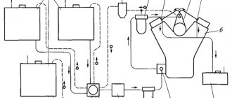
Rice. Diagram of the design and operation of a simple carburetor
1 – mixing chamber, 2 – diffuser, 3 – air pipe, 4 – sprayer, 5 – air hole of the float chamber, 6 – float chamber, 7 – needle valve, 8 – float, 9 – jet, 10 – throttle, 11 – inlet engine pipeline. , 12 – throttle lever.
In the upper part of the mixing chamber there is an inlet air pipe 3, in the middle there is a diffuser 2 having a narrowed flow area (neck), and in the lower part (outlet pipe) there is a damper 10, called a throttle, mounted on a roller passed through holes in the walls of the mixing chamber. Using lever 12 at the outer end of the throttle shaft, the throttle can be turned to the required position. The outlet pipe of the mixing chamber is connected to the inlet pipe 11 of the engine via a flange.
Carburetor tuning
Refinement or, in other words, tuning of the carburetor is carried out in order to achieve maximum power. At the inlet, the carburetor must have minimal resistance, since otherwise it is difficult to achieve acceptable mixture quality and cylinder filling at medium and high engine speeds. Boring the second chamber and raising the intake valves above 10.25 mm (relevant for 1.5 liter engines with high camshafts) allows squeezing out maximum power at high speeds.
A modified carburetor with a 24/24 diffuser diameter gives an increase when installing even a tuning engine. But it is worth noting that at low speeds and partial engine loads, a usual increase in the diameter of the diffusers will lead to a deterioration in its performance, since the vacuum in the diffuser area decreases and the atomization of gasoline and homogenization of the mixture worsen.
Carburetor tuning
– this is not only replacing all fuel jets with others of a larger cross-section, but also changing all the calibration data of the carb and its filling. Also, additional metering systems are introduced into the carburetor design. For this purpose, additional metering channels are drilled in the carburetor body.
Related terms
- Fuel filter
- Throttle valve
- Gasoline pump