The diesel engine boost pump is a low pressure fuel pump (LPFP). The main task of this device is the function of supplying fuel to the high pressure fuel pump. As a rule, the booster pump is installed on the injection pump “box” or in close proximity to the high-pressure pump.
Both pumps are connected using fuel pipes, through which diesel fuel is supplied from the high-pressure pump to the high-pressure fuel pump. At the same time, diesel fuel is cleaned, which involves passing it through special coarse and fine fuel filters. Next, we will look at the device, as well as the principle of operation of the fuel booster pump in more detail.
Low Pressure Fuel Pump Definition
To create a diesel fuel injection system, a low pressure fuel pump is installed. Its main purpose is to supply fuel from the tank to the high pressure pump. Stepped operation allows you to achieve higher efficiency from the equipment. The unit in question performs several functions:
- Supply of the required amount of fuel.
- Creation of sufficient excess pressure at the inlet to the injection pump. Otherwise, the entire system will not be able to function correctly.
- Creation of the required vacuum pressure in the suction pipe, which is sufficient to take fuel from the tank, taking into account the installed filter element.
- Providing pressure sufficient to overcome the resistance created by the fine filter.
- Preventing the effect associated with the release of bubbles of light volatile components during the movement of fuel in the system. A similar phenomenon occurs when transporting fuel in a system at high ambient temperatures.
Today, TNND is performed as a separate component, which is mounted together with other components. The main application is to power a diesel engine. It is worth considering that the failure of the node in question leads to the inoperability of the entire system.
Diesel engine power system
The diesel engine is increasingly gaining popularity among car enthusiasts; these units are in particular demand in the European market. Since its first appearance, the diesel-powered unit has undergone many changes and improvements in its design.
Today it is no longer the same engine that it was ten years ago; a modern diesel engine is in no way inferior to a gasoline engine in terms of noise, comfort, and environmental performance. And for some, such as efficiency, torque, power, and dynamic characteristics, it is even superior. By choosing a diesel power plant, the user receives a modern device, the operation of which, from the point of view of the average person, will not be difficult enough. However, there is a difference in maintenance between a gasoline engine and a diesel engine. The main difference between the two installations is the process of ignition of the working mixture. For its normal implementation, it is equally important to prepare this mixture correctly. The design and operation of the power system in diesel engines is much more complex than gasoline engines; in order to properly operate the unit, you need to understand how each of its mechanisms works.
Features and requirements for diesel fuel
The ignition process in a diesel unit occurs independently; the spark plug is completely excluded from it. To heat the air entering the cylinder, a glow plug can be installed, this is done in order to help the engine warm up faster during a cold start. When the installation warms up, the candles are turned off. The design of the fuel system of a diesel engine, in particular, the requirements for it, mainly depend on the specific characteristics of the fuel. Diesel is a mixture of fractions, mainly kerosene and gas oil, obtained after gasoline is extracted from oil. Diesel fuel, in comparison with gasoline, has the following properties and requirements:
- High viscosity, as a result of which the ignition process is slower;
- The ability to ignite independently is perhaps the most important property. The indicator is estimated by the cetane number; in modern types of fuel it has a value of 45-50; the higher it is, the better the fuel.
- Cleanliness is one of the main conditions for normal fuel supply to the power plant. It is carried out through a high-pressure fuel pump (HPF), it compresses the diesel fuel, increasing the pressure, after which the nozzle delivers and sprays it in the form of mist directly into the combustion chamber. Mixing with hot air and simultaneously compressing to a pressure of 3 to 5 MPa, the fuel ignites itself. If cleanliness is not observed, the fuel supply will be greatly complicated, as a result, the entire operation of the system is disrupted and stopped. Therefore, in diesel engines it is very important to use high-quality filters to clean the fuel from mechanical impurities, paraffin, and water.
- High density;
- Good lubricity, thanks to which the service life of diesel power plants is much superior to their gasoline counterparts;
- Pour point. This indicator allows you to divide the fuel mixture into varieties: summer, winter, arctic.
The boiling point is high, therefore its volatility is lower;
Basic provisions
The diesel power plant is an internal combustion engine, piston type, in which the mixture formation process occurs inside the cylinder, and the mixture is ignited due to compression. This differs from a gasoline unit, which requires the use of an external source, a spark plug, or a thermal element to ignite the mixture. Another process that occurs in the engine, which differs from its counterpart, is the process of mixture formation. In a gasoline unit, mixture formation occurs outside the cylinder, in a special device that mixes gasoline and air, then moves into the pipeline and is completed in the cylinder, during the intake and compression processes.
The principle of operation of a diesel engine
The general operating principle of a diesel unit that performs four cycles during operation can be described as follows:
- The process of filling the cylinder with clean air when the piston moves to the bottom dead center position, the air passes through the intake valve;
- Compressing the air until it is heated to its maximum, the piston moves to the top dead center position, the intake and exhaust valves are closed;
- Injection of fuel into the cylinder, its mixture with air and self-ignition, which generates a large amount of heat and increases pressure;
- The process of performing useful work due to the downward movement of the piston is stimulated by the action of gas pressure;
- The movement of the piston to the top dead center position, the release of exhaust gases through the exhaust valve.
Normal fuel system operation conditions
In order for the fuel system of a diesel engine, including equipment and mechanisms, to operate stably, certain requirements must be met:
- The combustion chamber must be provided with high temperature and pressure;
- Fuel and air, when mixed, must create a certain proportion;
- The crankshaft rotation at a certain frequency must correspond to the fuel injection advance angle;
- The air charge parameters must correspond to the most optimal state. This requirement is very important, since if fuel gets into an unprepared environment, the operation of the installation will be greatly complicated. The parameters that have a strong influence on the process are the following: compression, piston head temperature, quantity and proportion of air in the combustion chamber.
As for the compression ratio, its parameters differ significantly from those of a gasoline engine. In gasoline power plants it has a value of 10, while in diesel units it can be 20 or higher. This is due to the fact that a high compression ratio makes it possible to create a higher combustion chamber temperature, which greatly facilitates the ignition of the air-fuel mixture and the start of the power plant.
Purpose of the fuel system
The main purpose of the diesel engine power system is to transport fuel to the dosing and spraying mechanisms. The whole process takes place under high pressure conditions.
A special feature of the system is the fact that the amount of fuel must be supplied strictly at a certain rate necessary for successful operation of the engine. If you increase or decrease it, failures and breakdowns are possible. The amount of fuel and the duration of its injection are determined by the position of the cylinder of the device, and the beginning and completion of the process depends on the passage of certain holes by the plunger, which are located in the cylinder. The injection level itself is determined by the pressure at which the nozzle begins to open.
Power system, device
The diesel engine power supply system is characterized by a complex structure; it includes a whole range of different devices. To ensure proper functioning, fuel must not only be supplied to the injectors, but must be done so while maintaining a certain high pressure. This condition is necessary, since this is the only way to accurately adjust the fuel injection portion into the cylinder. The fuel supply system performs the following functions:
- Portion dosing of fuel depending on the load and operating mode of the power plant;
- Supplying fuel to the working chamber taking into account a given time period and a certain intensity;
- Maximum effective distribution of fuel mist so that it evenly envelops the entire volume of the working chamber;
- Maximum purification of fuel before supply to mechanisms and injectors.
Classification of TNND
There are quite a large number of different low pressure pumps on sale. The power supply system of diesel engines is equipped with the following designs:
- Oral.
- Geared.
- Piston.
In addition, classification is carried out according to the type of drive. Based on this feature, the following devices can be distinguished:
- Mechanical. In this case, rotation is transmitted from the injection pump shaft or the camshaft or camshaft.
- Electric. In some systems and cars, an additional electric motor is installed, from which rotation is transmitted to the device in question.
Rotor and gear versions are installed on passenger cars and commercial trucks. On trucks there is a diesel engine with an already built-in injection system.
Design features of rotary injection pumps
Rotary pump designs are widely used and may differ in design features. The main difference lies in the method of forming a closed chamber for the supplied fuel. Design Features:
- The basis of the design is the body, which is often made in a cylindrical shape. The body has slots of variable cross-section.
- The rotation is transmitted to a slotted rotor, into which rollers and flat blades are inserted.
- At the moment of rotation, the blades come into contact with the surface of the housing. This creates separate chambers that capture the fuel and discharge it through the outlets.
It is worth considering that this design has a fairly large number of disadvantages. The main one is the need to create a complex drive from a crankshaft or other drive. This point significantly increases the cost of the unit and reduces its reliability. To increase the reliability of the unit, an electric drive is installed, which ensures a reliable supply of fuel to the high-pressure pump.
Why did you need to switch to electric pumps?
With the advent and proliferation of electronically controlled injection systems, the use of mechanical pumps has become impractical. The fact is that it is necessary to maintain a higher pressure in the fuel line of injection systems, and it is impossible to achieve it using a mechanical diaphragm pump. In the injection system line, it is necessary to maintain a constant fuel pressure of 1 to 5 bar for uninterrupted operation of the injectors. In addition, the fuel flow supplied by the mechanical pump due to cyclic operation had significant pulsation. If fuel was supplied to the injector in this mode, the injectors would experience periodic fuel starvation, which would lead to engine malfunctions.
Gear TNND
Gear injection pumps resemble the design of oil pumps. This design is also quite common. Key points:
- The body serves as the basis of the structure. It has a high degree of tightness and strength.
- Inside the housing there are two gears that are meshed. Both gears are sized for the teeth to contact the surface of the housing. This ensures the creation of sealed chambers.
- At the moment of rotation, the gears capture fuel, after which they throw it into the outlet holes.
The mechanism under consideration has all the advantages and disadvantages that are characteristic of rotary versions. However, gear ones are characterized by a simpler and more reliable design, they are cheaper to maintain, due to which they have become very widespread. Piston version of the pump
Piston designs have also become very widespread. Low pressure pumps come in two types:
- Single action. In this case, the maximum amount of fuel is removed in one cycle.
- Double action. Such a device is characterized by the fact that two fuel pumps are performed in one working cycle.
A single-acting pump has a simpler design. Its features:
- A cast body is used as the basis.
- The housing has an inlet chamber, a discharge chamber, and a central area for the piston to move.
- A single design is created by a piston, a rod, a cylindrical pusher, a roller with an eccentric cam shaft.
- In the suction cavity there is an inlet valve through which fuel is drawn from the tank. The outlet is located in the discharge section.
At the time of operation, the piston creates a reciprocating motion. This design is less practical, but is also quite common due to its high efficiency. The double-action version has a more complex design, but this significantly increases the efficiency of the mechanism.
Fuel lift pump
The fuel priming pump is used to supply fuel from the fuel tank through the fuel filter to the fuel pump. On 4ch8.5/11 diesel engines, a piston-type fuel priming pump is installed. It is mounted on the body of a four-plunger fuel pump and is driven by the pump camshaft.
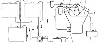
The operating diagram of the fuel priming pump is shown in Fig. 26.
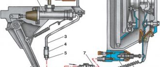
The piston of the pump 11 is driven from the cam through the roller pusher 13. When the roller runs off the cam (Fig. 26, a), the piston moves downward under the action of spring 7. Fuel enters the space above the piston through inlet valve 8. Discharge valve 6 is closed. At the same time, fuel from the cavity under the piston is pushed into the discharge line.
During the reverse stroke of the piston (Fig. 26, b), under the action of a cam running onto the pusher roller, fuel through injection valve 6 and channel 4 enters the space vacated by the piston when it moves upward. The feeding process is repeated with each full revolution of the cam.
If the pump capacity exceeds the demand of the fuel pump, then fuel backpressure arises in the space under the piston and in the discharge line, under the influence of which spring 7 is not able to move the piston to its lowest position. The piston stops at a certain middle position. The spring pressure in this case is balanced by the back pressure of the fuel (Fig. 26, c).
Rice. 26. Scheme of operation of the fuel priming pump:
a - injection; b - release; c — idling; 1 - eccentric; 2 — pusher roller; 3 —, space under the piston; 4 — connecting channel; 5—fuel removal; 6 - discharge valve; 7 — piston spring; 8 — inlet valve; 9 — fuel supply; 10 — space above the piston; 11 - piston; 12 — pusher spring; 13 - pusher
When the discharge line is completely blocked, the piston will stop in the upper position and the pusher rod will not touch the piston. As fuel consumption increases, the piston begins to move down. Thus, the piston stroke, and therefore the fuel supply by the pump, automatically changes depending on the fuel consumption. The fuel supply pressure is determined by the spring preload and varies slightly under different operating conditions.
The fuel priming pump (Fig. 27) consists of a cast iron body 1, into the cylindrical bore of which a steel piston 3 with a spring 2 is inserted. The bore is hermetically sealed from the outside with a plug 10. The space between the plug and the piston is connected by channels to the cavity above the inlet valve 12 and to the cavity under the discharge valve valve 11. Fuel is supplied and discharged through union bolts screwed into the pump housing.
The pump piston receives movement through rod 4 from pusher 5 with roller 8 moving in the bore of the housing. The protruding ends of the roller axis 7 slide in the longitudinal grooves of the bore, which prevent the pusher from turning. The pusher has a spring 9, with which it is constantly pressed against the surface of the fuel pump cam or against the lever on the hatch cover.
The guide hole in the pump body, in which the rod 4 moves, has an annular groove. The fuel penetrating through the gap between the rod and the guide hole is discharged out through the channel. This prevents fuel from entering the fuel pump housing or into the cavity of the crankcase and diluting the oil present there. The latest pump design does not have this channel. Fuel leakage through the gap between the rod and the guide hole is eliminated by precise grinding of the rod along the hole. As a result, the rods in the pumps are not interchangeable. To fill the fuel system with fuel and remove air from it before starting the diesel engine, a manual fuel pump is installed on the suction line of the pump, which consists of a housing 18, a piston 14, a rod 17 and a button 15. To pump the fuel, you need to unscrew the button 15 and pull it up. The piston connected to the button by the rod will also move up. As a result of the vacuum formed under the piston, fuel will fill the cavity under the piston through the suction valve. During the reverse stroke of the piston, fuel is pushed into the discharge line. After pumping is completed, the button is screwed onto the body again and ball 13, rolled into the bottom of the piston, tightly locks the channel in the body.
Didn't find what you were looking for? Use the search:
Best sayings: Only sleep brings a student closer to the end of the lecture. And someone else's snoring alienates him.
8940 — | 7611 - or read all.
Selection and measurement of TNND
The type of pump in question operates under high loads for a long period. Due to this, rapid wear of the main elements occurs. Excessive wear and tear may cause the device to break. In most cases, to restore the structure, the main elements are replaced.
If the damage is serious, then you have to completely replace the unit. Serious defects include the following:
- Cracks and other defects in the body. The chambers of the housing must be characterized by high tightness, since pressure is created during operation of the device. As a result, liquid may be forced out through the housing.
- Fracture and destruction of main parts. Improper operation and untimely maintenance, too much load can cause destruction of the main elements.
- Deformation of key non-separable parts. This occurs due to the operation of the device with obvious defects.
It is worth considering that when replacing a pump, attention should be paid to the corresponding models. All work on replacing the device and setting it up should be entrusted exclusively to professionals, since mistakes made can lead to very serious consequences.
CVT: general characteristics
By and large, a variator (CVT - continuously variable transmission) is a subtype of automatic transmission. And a car with this gearbox is at first glance identical to an automatic transmission. But the operating principle of the variator is completely different. There are no fixed gears in it at all. Due to this, switching occurs smoothly, without shocks.
The functionality of CVT is a continuous change in the gear ratio according to the acceleration and deceleration of the car.
The variator is a continuously variable friction transmission. The counter-rotating pulleys are brought together by a V-belt. The main gear is connected to the engine using a shaft, and the driven gear is responsible for the wheels.
The more one pulley touches, the smaller the radius of contact of the other. This is how a car with CVT accelerates and brakes.
The variator also includes:
- reverse device;
- intermediate link associated with the engine;
- ECU.