When we get into the car, the first thing we do is start the engine using the starter. This mechanism is the main unit of the starting system; its task is to spin the crankshaft to a certain frequency necessary to start the car engine.
But what to do if the starter does not work and the car does not start? In order to correctly assess the current situation, determine a possible breakdown and correct it, you need to understand the design and principle of operation of the car’s starting system.
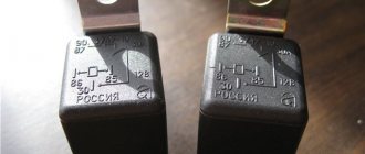
One of the weak points in this system is the starter relay.
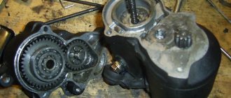
The starter is a device in the form of a metal cylinder of small length (15 - 20 cm) and diameter (7 - 10 cm). An energizing relay is connected to the mechanism body. The place where the starting unit is located is the connection between the engine and the gearbox of the vehicle. The starter is secured with a bolt connection.
Top-5 foreign manufacturers of starters.
| No. | Name | A country |
| 1 | Bosch | Germany |
| 2 | Denso | Japan |
| 3 | Denso | Belarus |
| 4 | Fenox | Belarus |
| 5 | Valeo | France |
Other reputable manufacturers include CARGO (Denmark), UNIPOINT (UK), WPS (USA), Protech (France). There are also domestic, quite good brands -
- KZATE (Samara),
- Eltra (Rzhev),
- StartVOLT (St. Petersburg).
Main starter relay
The car's electric starting system includes, in addition to the starter and relay, also starter on/off elements, various connecting wires, the main power source (battery), etc.
The starter relay or VR is activated after turning the key in the ignition switch. The BP armature and the freewheel lever move, and the bendix engages with the flywheel crown. This ensures normal engine starting.
To be able to adjust the system, you need to disconnect the current wiring from the VR. The control terminal is marked on the terminal with the letter M.
Then the battery is removed from its original place and connected to the M and S terminals marked on the terminals. Thus, the purpose of the operation performed is to shift the bendix. And in order to connect the BP to the starter, you must first adjust the gap between the bendix and the stop. It is also recommended to adjust the gasket located between the drive and the BP.
Additional VR starter
On modern cars, an additional VR starter is a priori provided. On older cars, the relay is installed and connected independently.
The advantages of installing an additional VR are obvious:
- Protects the starter device from burnout of contacts in the lock, which occurs for various reasons (long start-up, banal wear, etc.);
- It has a positive effect on the loading of contacts of the same ignition switch, as a result of which the contacts remain operational longer;
- Protection of the starter from a situation where, due to a “glitch” of the key in the ignition switch (the engine has started, but the starter continues to spin).
You can check whether the additional VR is installed on the car like this:
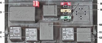
- Look in the “black box” (fuse box);
- Turn on the starter device in the engine purging mode - if the additional relay is on, then the starter must turn off on its own after a few seconds.
Connection of additional VR
Here's how to connect:
- Fix the relay in any convenient place (you can on the stud of the glass cleaning fluid reservoir);
- Connect the cable to the starter;
- Remove the red wire from the flat terminal of the main relay, and in its place insert the wire from the additional VR;
- Connect the other wire of the new BP with an 8 mm tip to the positive of the starter;
- Place contact 30 of the additional VR onto the released contact of the main VR;
- Screw the short wire numbered 85 to the body (ground).
Additional relays can be purchased in stores. They are sold as a kit, where everything is provided for proper self-installation.
Forget about fines from cameras! An absolutely legal new product - NANOFILM, which hides your license plates from IR cameras (which are installed in all cities). More details at the link.
- Absolutely legal (Article 12.2.4).
- Hides from photo and video recording.
- Installs independently in 2 minutes.
- Invisible to the human eye, does not deteriorate due to weather.
- 2 year warranty
Starter relay description purpose device repair photo video
Share “Starter relay description purpose device repair photo video”
The movement of any car begins with starting the engine . If you want to understand the principles of operation of the main components of a car, we recommend starting your study with the starting system. One of the most vulnerable points of this system is the starter relay. Almost everyone has heard about this detail, but not many understand the principle of its operation. Before we start talking about the starter relay, it is worth noting that the design of the car simultaneously has two parts with the same name, only the first is responsible for turning on the starter, it is usually located in the engine compartment, and the second is the starter solenoid relay.
FAQ
Let's touch on several interesting questions that both novice drivers and very experienced car enthusiasts may ask. So:
- What is the current of the starter solenoid relay? Answer : Much depends on the model of starter and relay, but in most devices a current of 15-20 Amps passes through the control contact. In some cases this current is greater, but also remember that the strength of the current depends on whether the contacts are clean;
- How to disassemble the starter solenoid relay? Answer : This question was addressed above. In this case, you can get to the “filling” of a non-separable relay, although you cannot do without special tools and damage to the integrity of the case.
We have already described the relay repair process above. Even an inexperienced car enthusiast will not have any particular difficulties with this. The problem can only arise during the search for relay parts. However, many repair parts can be found from the already mentioned Danish company Cargo. Most of the goods offered by the company are produced in the countries of Southeast Asia, but their quality is quite high.
WHAT IS A STARTER RELAY
So, let's start with the basics. Two relays are responsible for the starter. The first is installed in the engine compartment. The design can have its own housing or be installed in a common unit.
In this article, we will be much more interested in the second relay, which is responsible for the operation of the starter, namely the retractor. It performs the following functions:
- redistributes energy between the starter and the electromagnetic relay;
- feeds Bendix gears;
- synchronizes the starter components,
- returns the gears to their original position after you turn off the engine.
In the automotive world, this unit has two names: traction and retraction. The first is most often used in specialized literature, the second is popular.
To understand why a starter solenoid relay is needed, let’s look at the engine’s operation schematically. To start the engine, the crankshaft must begin to rotate. Only after this does the fuel-air mixture ignite in the combustion chamber.
Usually the engine starting process takes place within a second. The role of the relay in it is quite simple. Thanks to it, the gear elements engage with each other. It synchronizes the operation of the starter. This unit also removes the bendix from the flywheel.
Typical faults
Among all the problems that happen with the starter, most are associated with this traction relay. Let's look at the most common faults.
During operation, the starter experiences enormous loads. Most often it is installed at the bottom of the engine. This is an area that receives a large amount of dust and dirt, water, and other liquids. Structurally, the retractor relay is combined with the starter housing. If we take into account the location of the relay, it also experiences serious loads. Inrush currents when starting the engine can reach up to 500 A and above. This leads to destruction of the contact pads, contact plate and contact bolts.
Among the main malfunctions are breaks, destruction or burnout of the windings. Also, contact zones on the heels and contact plate are often destroyed. The contact bolt clamps are burning. Often the plug breaks, the relay rod or armature gets stuck. The springs are destroyed.
Main components and operating principle of the engine starting system
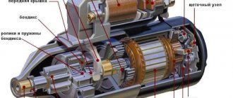
To understand the operation of the starting system, it is worth first considering the design of the car starter. The purpose of the starter is to start the engine. The starter device for all cars is identical, they differ only in size or parameters. So, the design consists of the following required elements:
- Electric DC motor;
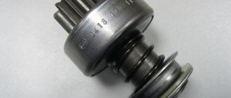
- Bendix;
- Starter solenoid relay.
The main role here is played by the electric motor, and the bendix and starter relay are auxiliary elements. The electric motor includes standard elements such as a stator, a rotor, and a starter brush assembly. Bendix, even the smallest detail, plays a very important role. It is necessary to transmit rotation from the electric motor to the gear ring of the engine flywheel, thereby ensuring starting.
Until 2000, the bendix was located on the same shaft as the rotor, and then a new arrangement appeared, where the bendix began to have its own separate shaft and rotate through a gearbox.
That’s why we sometimes hear the name “gear starter”. The starter retractor relay is a more complex element and performs several functions at once:
- Redistribution of electricity supplied from the battery between the electric magnet of the starter relay and the electric motor;
- Synchronization of the operation of all components when starting the engine;
- Feeding the Bendix gear until it engages with the flywheel ring gear;
- Returning the working gear to its original position after starting the engine.
The principle of operation of the starter is as follows: in order to start the car engine into operating mode, it is necessary to forcibly rotate the crankshaft until the fuel mixture in the cylinders begins to burn.
Typically, it takes quite a bit of time to start a working engine. The task of the starter retractor relay is to maintain the engagement of the Bendix gear with the flywheel and rotate the crankshaft equally until the start occurs. No more and no less. If you hold it longer, you can break parts, and if you hold it longer, the engine won’t start.
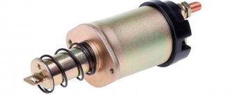
Device
The relay consists of the following elements. So, the mechanism is assembled in a housing. It contains two windings - a holding winding and a retracting winding. Sometimes these windings can be combined into one. The relay also has an armature and a core. The first one is equipped with a return spring. In addition, the device is equipped with a fork, rod, damper spring, contact plate, bolts and nickels.
All the main work in this relay is performed by the armature and winding. After an electrical impulse arrives from the battery, an electromagnetic field appears inside, causing the armature to move along the tube. When the impulse stops being supplied, the armature leaves the core.
The relay return spring is compressed as soon as the armature begins to act on it. Along with the stroke of the spring, the bendix begins to rotate.
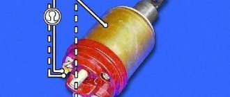
A magnet with windings inside a relay is nothing more than a pair of coils with different properties. One of them performs only a retracting role and is connected to an electric motor, the other is only a holding role and is connected to the control terminal.
At the moment of launch, the armature is affected by the magnetic field of the second coil. It prevents it from leaving the core.
DIAGNOSTICS AND REPAIR
CHECKING THE SYSTEM
Before checking the solenoid relay, you need to test the starter itself. This check will allow you to understand what exactly is not working in the system. Insert the key into the ignition and turn it.
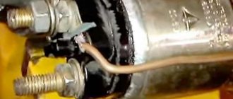
Next you will need to open the hood and get to the starter. You must make sure that this is the case. To do this, bridge the two contacts. They are made in the form of two copper bolts. These structural elements are attached to the rear of the solenoid relay (on the body). If, after the manipulations you have performed, the mechanism rotates, then the problem is in the solenoid relay.
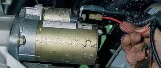
In some cars, reaching the starter is very difficult, and sometimes even impossible. In this case, you will have to partially disassemble the system and dismantle the device itself.
After removing the starter, place it on the ground. Place the battery nearby. Connect the leads of the two devices. In this case, the battery ground is connected to the starter ground.
When the wires are connected, the starter solenoid relay will operate. At first there will be a rather loud click. If the mechanism operates too slowly, be sure to check the contacts. This situation may be caused by the fact that they are burnt.
Checking the retractor relay with the starter removed
It is more convenient to check the functionality of the relay with the starter removed. But before dismantling, several operations are performed to identify the problem:
- Check the reliability of the terminals, the condition of the battery, remove oxides from the contacts and terminals of the battery.
- Make sure that the wiring is securely fastened to the starter with nuts. If corrosion is noticeable, clean the contacts with fine sandpaper.
- Check the condition of the starter enable relay.
The starter is removed after disconnecting the wires that go to it and unscrewing the mounting bolts. In some cars, this operation will take a lot of effort, since the unit may be located in a poorly accessible engine compartment.
After removing the starter, it is cleaned of dirt, the oxidized contacts are treated with sandpaper, and the test begins in the following order:
- The unit is placed next to the battery, from the terminals of which there are wires with “crocodiles”.
- The positive and negative terminals are connected to the corresponding contacts on the retractor.
- The free end of the negative wire is touched to the starter housing and the result is observed:
- If there is a distinct click in the relay, then it is working;
- If the retractor does not show “signs of life,” it needs to be replaced or repaired.
WHAT DAMAGES CAN BE IN THE EXTRACTOR RELAY
Usually the whole problem lies in burnt contacts or their sticking; other faults include:
- coil burnout,
- mechanical damage,
- natural wear and tear of parts.
In the latter case, the starter solenoid relay will need to be replaced. There are a number of signs that most likely indicate that the problem is in this particular node, these include:
- After the engine starts, the starter continues to operate. This is indicated by a clearly audible buzzing sound.
- When you turn the key in the lock, you can hear a distinct clicking sound. This means that the main system starts, but the starter does not work.
- When you turn the key, the starter idles. The engine remains inactive.
These signs most likely indicate that the malfunction is related to the starter solenoid relay.
HOW TO CONNECT
Many motorists are afraid that after they repair the solenoid relay, they will not be able to connect it. In reality, the connection diagram is quite simple. Moreover, you compose it yourself.
To carry out reverse dismantling, you must first mark the disconnected terminals. This will allow you to connect everything correctly after the repair is completed. Also, before installing the relay, you need to clean the contacts. For degreasing, use a modern liquid sold in automotive stores.
REPAIR
It is worth recognizing that on machines of the same series, the starter solenoid relays are very similar. The most striking in this context is the following automobile line:
In principle, all starter solenoid relays have the same design. Accordingly, their repair process is similar. The main differences lie in the fastening systems. Also, cores can have different designs. But the general scheme is very similar.
So, in order to repair the starter solenoid relay, you first need to dismantle and disassemble it. Here, in fact, lies the main problem. In most cars, these units are non-separable. All that remains for the driver in this case is to make a replacement.
This is interesting: Installation diagram of window lifter cables for UAZ loaf
It is very important to maintain a clear sequence during repairs. Otherwise, you risk not only damaging the part or other systems, but also getting injured. The process itself consists of the following stages:
- Disconnect power from the battery.
- Clean the part from dust and dirt. Otherwise, foreign particles may get inside the unit, causing damage to it.
- Unscrew the brush assembly nut.
- Remove the contact from the bolt.
- Unscrew the clamping screws. They are the ones that connect the relay to the ground of the car.
- Unscrew the ends of the nuts.
- Divide the device in half.
- Replace the core.
- Reassemble.
Before putting the device back into the car, start it. Reinstallation should only be carried out after preliminary testing. Once everything is assembled, do a few test runs. Only after this go on the road.
WHAT ELSE CAN BROKE?
Most damage to the solenoid relay is associated with the burnout of certain of its elements. Most often, electromagnetic circuits burn out. Windings and contacts are also subject to similar destruction. In some cases, the cause of failure is metal fatigue.
However, ignition problems are not always associated with the starter or solenoid relay. If the repair does not give the desired results, check the electrical circuit. Also look at how much charge the battery has.
Every car owner can check and repair the solenoid relay. The process itself does not take much time, and its complexity in most cases depends on how conveniently the starter is located.
Share “Starter relay description purpose device repair photo video”
Car starter connection diagram
A lot of time has passed from the time the car was created, or rather the introduction of a starter into it, to the present day, but the scheme has remained virtually unchanged. The first connection diagram for the starter looked approximately as shown in the figure below, now it has changed a little, which I will explain below.
The battery positive (1) is connected by a thick wire to the starter terminal (3). The starter current at start-up can reach hundreds of amperes. Next, the plus, through the generator (2), is supplied to the ignition switch (5). After closing the ignition switch contacts, the intermediate relay coil (4) is energized, which closes its contacts. One of the relay contacts is connected to the positive wire, therefore, after their closure, the windings of the solenoid relay are energized. We will look at how the starter and solenoid relay work in another article.
Such schemes were used in Soviet-made cars; foreign cars, if they used them, moved away from such schemes very quickly. The first starters were massive and had low efficiency. Consequently, the control circuits required the same not small currents. An intermediate relay is used to pass these currents. Modern starters have less power. This was achieved by using permanent magnets on the stator poles and installing a step-down gearbox on some models. This made it possible to get rid of the intermediate relay and supply voltage from the ignition switch directly to the coils of the solenoid relay.
Computer keyboard circuit Starter blocking device Simple starter blocking Power supply for 9-volt radio equipment from the car's on-board network Circuit of a desulfating charger Simple stabilized power supply with super-available parts Laboratory power supply controlled by a microcontroller Laboratory power supply from an AT power supply Power supply from an uninterruptible power supply
Notes
Categories:
- Switching devices
- Relay
- Relay protection
- Automation
Wikimedia Foundation. 2010.
See what “Relay” is in other dictionaries:
relay - , constant; Wed An automatic device that closes or opens electrical circuits in response to certain phenomena to which it is designed to respond. Switch relay. Electromagnetic relay. ◁ Relay, oh, oh. R oe ... ... Encyclopedic Dictionary
relay - uncl. Wed relais < relayer change, replace. unit Traveling from one station to another on horseback. We go to one station, then another, a man gets into the stagecoach, perhaps a very respectable one, but without a nose, the Englishwoman suffered for two, three relays and began to beg... Historical Dictionary of Gallicisms of the Russian Language
relay - a device for automatic switching of electrical circuits based on an external signal. It consists of a relay element (usually with two stable states) and a group of electrical contacts that close (or open) when the state changes... ... Encyclopedia of Technology
RELAY - A sensitive electromagnetic device used in a telegraph. Dictionary of foreign words included in the Russian language. Chudinov A.N. 1910. RELAY is a very sensitive electromagnetic device through which. the current of the telegraph line passes and... ... Dictionary of foreign words of the Russian language
RELAY - (French relais) a device for automatic switching of electrical circuits based on an external signal; consists of a relay element (with two stable equilibrium states) and a group of electrical contacts that close (or open) when... ... Big Encyclopedic Dictionary
RELAY/ - (re), uncl. Wed (French relais) (physical tech.). An electromagnetic device that controls the action of something. signaling or other apparatus, machine or network by closing or opening an electrical circuit. Cathode relay (radio) is the same as cathode... ... Ushakov's Explanatory Dictionary
relay - , uncl. Wed (French relais) (physical tech.). An electromagnetic device that controls the operation of some signaling or other device, machine or network by closing or opening an electrical circuit. ❖ Cathode relay (radio) is the same as... ... Ushakov's Explanatory Dictionary
RELAY - RELAY, several Wed (specialist.). A device for closing and opening an electrical circuit. Electromagnetic river | adj. relay, oh, oh. Ozhegov's explanatory dictionary. S.I. Ozhegov, N.Yu. Shvedova. 1949 1992 ... Ozhegov's Explanatory Dictionary
relay - noun number of synonyms: 11 • barorele (1) • hydrorelay (1) • kipp relay (1) • ... Dictionary of synonyms
relay - for controlling electrical circuits; relay A relay action device designed to make changes in electrical circuits (usually control, signaling and communication circuits) ... Polytechnic terminological explanatory dictionary
- Control and protection relays. Volume 1. Control relay (+ CD-ROM). Control and protection relays belong to the class of low-current switching devices and are used in electrical devices as a control and protection element. Control relay and… Read more Buy for 2652 RUR
- Control and protection relays. Volume 2. Protection relays. Directory. Control and protection relays belong to the class of low-current switching devices and are used in electrical devices as a control and protection element. Control relay and… Read more Buy for 1520 UAH (Ukraine only)
- Control and protection relays. Volume 2. Protection relays. Directory. Control and protection relays belong to the class of low-current switching devices and are used in electrical devices as a control and protection element. Control relay and… Read more Buy for 1469 RUR
Other books on request “Relays” >>
How to make a start button instead of an ignition key in a car with your own hands
Oddly enough, this issue very often worries motorists and not only for aesthetic reasons - in the spirit of the times. The contact group located behind the ignition key very often fails, and changing it is far from an easy task.
In older cars, often the wires from the starter itself are connected directly to contacts inside the contact group, which close when the ignition key is turned. When the starter is activated, a very large amount of energy is consumed, which means a large current flows (the contacts strike a spark). Over time, a burnt deposit forms on the contacts or they completely burn out, no longer providing reliable contact. Newer vehicles have a separate relay that closes the starter contacts when the ignition key is turned.
What is it used for?
This protective device is necessary, just like a circuit breaker. However, this device has a different purpose - to monitor voltage.
Overvoltage in the network is a common cause of failure of expensive equipment, the repair and replacement of which costs a pretty penny, since failure from overvoltage is not covered by warranty. And as a rule, such surges last a few seconds until the protection at the substation is triggered; this is quite enough for the electronics in the house to fail. Look at how many devices you have plugged in, even if you don’t use them, at the moment, they are all a potential threat.
To avoid this, a voltage relay has been created that monitors the state of the electrical potential in your apartment around the clock, and will instantly de-energize the network in the event of an abnormal change.
Pay attention to the single-phase relay RN-104 volt control from the manufacturer Novatek Electro. Easy to set up and operate, it will guard the electrical network of your home or apartment
Below we will look at the design and operating principle of a voltage control relay.
The main advantages of using a relay in the starter power circuit:
— Such a system is more reliable, since the relay is designed for high currents and lives much longer. — The relay can always be replaced — The contact group behind the ignition key works for a very long time, since it only turns on the relay that takes the main load.
Regardless of whether your starter is turned on by a relay or directly by a contact group, all operations to connect the starter are still performed by turning the key.
First you need to determine which contacts are responsible for the start and connect them to the start button.
To do this, you need to disassemble the plastic protection under the steering wheel of your car. Very often, a connector with all the necessary wires is connected to the contact group of the key well at the back. There should be locking tabs on both sides of this connector. You need to press on them and pull out the connector.
If you have an old car, inspecting the contact group connector you will most likely find the two thickest wires. Very often one of them is red - these wires are directly connected to the starter. If you connect them with the ignition key turned, your starter will most likely start spinning.
Then you can go the simple way. You can simply install the button and connect these two wires to it, placing the button in a place convenient for you. The button should be non-latching, that is, when pressed, it should close the contacts, and immediately after you release it, open it.
Do not forget that you will operate the button in the same way as a key. We press the button, wait until the starter spins, and as soon as the engine starts, release the button.
But do not forget that very large currents will pass through the button and most likely such a button will burn out.
We used a vandal-proof chrome button - it failed after about half a year.
If you have a newer car and the starter in it is connected using a relay, you will need to find among the many wires exactly those that are responsible for controlling the relay.
To do this, you can ring the tester in resistance measurement mode on all the wires on the car body. All wires that ring are marked as ground (or minus), since they are all shorted to the body.
Next, touch each of the remaining wires with one tester probe and the other probe to the body in voltage measurement mode.
We need to find the wire on which 12 Volts appears exactly at the moment you turn the key, that is, when your starter starts spinning.
If you find this contact, you need to check how the system works.
— Find some kind of contact on which, relative to ground, there is always 12 Volts.
— Turn the ignition key to ignition mode (the starter must be turned off)
— Check again the wire you found:
* check that it is not connected to ground and is not short-circuited to the body,
* check that voltage appears on it when you turn the key to the starter mode
- Now try using a separate wire to connect the wire that you found in the paragraph above to the wire that always has 12 Volts.
If after connecting your starter turns over, then you have found the wires that connect when you turn the key so that the starter turns over.
Your work is finished here. You just need to bring these wires to a convenient location on the dashboard and connect the button to them.
If your car is an old model, it is best for you to install a separate relay to turn on the starter and close only the relay contacts, which in turn will connect the starter contacts.
You can see which contacts are responsible for what on the relay body, or you can open it and see how it works.
Oddly enough, it makes absolutely no difference where to connect + (plus) and where - (minus) on the contacts of the relay coil - in any case, it attracts the desired contact and connects the line.
That is why you can use the positive contact with 12 Volts already connected to the relay. It can be connected to the coil contact. Accordingly, the second contact is connected to ground through the button.
It is these two wires - minus (ground) - the second contact of the coil that must be brought out in a place convenient for you and the button connected to them.
The remaining relay contacts for the main line must be connected to the wires on the contact group that connect the starter.
Don't forget about high power when connecting these wires. The wires must be very thick and the connections very secure.
The wires can be directly soldered to the relay contacts, but most likely this will be a mistake, since it will be quite difficult to replace it later. In our case, when heating the contacts with a soldering iron, they melted the plastic body of the relay and moved, closing the contacts inside the relay.
It is best to find a remote connector for such relays, which is sold separately. Unfortunately, it does not please with its reliability or quality of workmanship.
The wires on the connector pins are very thin and very difficult to hold on to. We recommend that you remove each pin and solder secure thick wires to them.
For convenient connection, you can attach screw terminals to the wires.
It is best to place the relay in a place where it will be convenient for you to reach it later to replace or check the operation of the system.
Remember that you do all the above actions at your own peril and risk; we do not recommend that you undertake such complex electrical work if you do not have skills in electrical engineering. We wish you good luck in all your endeavors.
How to start a car
There are no car enthusiasts who, at least once in their lives, have not found themselves in a situation where their car’s starter or battery stubbornly refused to do its job. And this often happens at the wrong time, when you need to go urgently, but there is no time for repairs. Let's talk about how to solve this problem yourself.
How to start a car in difficult conditions?
The most common case of engine failure is a broken starter. How to start a car if you have such a misfortune? Of course, you need to short-circuit the starter terminals. But before you move on to closing the unit, you need to try to find out the reason for the starter failure. After all, having recognized it, you can try to cope with it yourself, without resorting to the services of specialists.
So, starter failures include:
- breakdown of the starter relay;
- breakdown of the starter retractor relay;
- Bendix that has fallen into disrepair;
- burnt out armature winding.
If any of the above parts are damaged, you can immediately look for a method to start the engine yourself. There are few options for such methods, but they work flawlessly. It will also be useful to read the article How to start a car in cold weather.
How to start a car correctly if the starter is broken?
- The first most reliable option for starting the engine is the so-called push start. Ask passers-by or neighbors in the parking lot to push your car. In turn, turning on the ignition and first gear, start the engine and press on the gas until it starts. Please note that this method is suitable for a manual transmission. In the case of an automatic transmission, starting the car in this way will be much more difficult, since you will need to put more effort into pushing. For reference, there is a good article: Starting a car with a pushrod.
- The second effective option is towing, i.e. your car is towed by another car, and after driving some distance, you start the engine. Be extremely careful when starting this way. Please note that when you start the engine, the car will accelerate and may overtake the towing vehicle and damage it.
- The next option for starting the engine requires initial technical training from the driver. It involves shorting the starter terminals directly using a pry bar or screwdriver. It should be noted right away that the terminal jumpers at hand will only help if the starter solenoid relay breaks down. To perform this procedure, you must short-circuit the power terminals of the solenoid relay. But before jumpering the terminals, do not forget to put the car on the handbrake, the transmission in neutral and turn on the ignition.
How to start a car with a dead battery?
Let's look at the causes of this problem and their solutions. So, the reasons for battery discharge may be the following:
High energy consumption by third-party energy consumers. In this case, you need to turn off all electronics, including the alarm. If the engine starts running, it means there is still enough charge in it. If the previous procedure did not help, then there is very little charge left. Then you need to turn off the engine and wait 5-10 minutes. After this, try to start the engine again. The remaining charge can last for a minute of driving. Then you will need to turn off the engine again and repeat the procedure. When the battery is completely discharged, the so-called “lighting up” can help. This term means charging from the battery of another car using special wires with “crocodiles” - metal clips. You need to connect one end of the wire (red) to the positive terminals of the car batteries. The other end (black) is connected to the negative terminal of the donor and some metal part of the recipient machine's engine. In this case, a spark may jump, which is normal.
During charging, it is important that the machines do not touch
So we looked at several simple options on how to start a car. We also recommend that you read the article How to start a car correctly.
How to connect a starter relay: rules for connecting a relay
As you know, normal functioning of a car is impossible without a good and clear start. When setting up the electric starting system of a car, great importance should be paid to the “starter-relay” circuit. It is important to know how to connect the starter relay so that no difficulties arise in the entire starting system.
Main starter relay
The car's electric starting system includes, in addition to the starter and relay, also starter on/off elements, various connecting wires, the main power source (battery), etc.
The starter relay or VR is activated after turning the key in the ignition switch. The BP armature and the freewheel lever move, and the bendix engages with the flywheel crown. This ensures normal engine starting.
How to properly connect the starter relay
To be able to adjust the system, you need to disconnect the current wiring from the VR. The control terminal is marked on the terminal with the letter M.
Then the battery is removed from its original place and connected to the M and S terminals marked on the terminals. Thus, the purpose of the operation performed is to shift the bendix. And in order to connect the BP to the starter, you must first adjust the gap between the bendix and the stop. It is also recommended to adjust the gasket located between the drive and the BP.
Additional VR starter
On modern cars, an additional VR starter is a priori provided. On older cars, the relay is installed and connected independently.
The advantages of installing an additional VR are obvious:
- Protects the starter device from burnout of contacts in the lock, which occurs for various reasons (long start-up, banal wear, etc.);
- It has a positive effect on the loading of contacts of the same ignition switch, as a result of which the contacts remain operational longer;
- Protection of the starter from a situation where, due to a “glitch” of the key in the ignition switch (the engine has started, but the starter continues to spin).
This is interesting: Wiring diagram for VAZ 2114 power windows
How to connect the additional starter relay
You can check whether the additional VR is installed on the car like this:
- Look in the “black box” (fuse box);
- Turn on the starter device in the engine purging mode - if the additional relay is on, then the starter must turn off on its own after a few seconds.
Connection of additional VR
Here's how to connect:
- Fix the relay in any convenient place (you can on the stud of the glass cleaning fluid reservoir);
- Connect the cable to the starter;
- Remove the red wire from the flat terminal of the main relay, and in its place insert the wire from the additional VR;
- Connect the other wire of the new BP with an 8 mm tip to the positive of the starter;
- Place contact 30 of the additional VR onto the released contact of the main VR;
- Screw the short wire numbered 85 to the body (ground).
Additional relays can be purchased in stores. They are sold as a kit, where everything is provided for proper self-installation.
How to pay TWICE LESS for GASOLINE
- Gasoline prices are rising every day, and the car's appetite is only increasing.
- You would be happy to cut costs, but is it possible to live without a car these days!?
But there is a completely simple way to reduce fuel consumption! Don't believe me? An auto mechanic with 15 years of experience also didn’t believe it until he tried it. And now he saves 35,000 rubles a year on gasoline! Read more about this at the link.
What does it mean “the starter takes over the current”?
The main reasons why the starter can take on current are:
- Lack of good contact on electrical wiring and elements of the ignition system;
- Sufficiently low electrical or high mechanical resistance;
- Failure of the constituent elements (due to the deterioration of the bushings, the armature begins to touch the starter when rotating). This leads to strong heating and destruction of parts. The gearbox also needs to be checked, because it may also need additional lubrication.
Your actions
To understand the true reason, it is necessary to carefully study the mechanism and check all its elements. The first step is to determine the location of this mechanism. Access to it is usually very limited, but you can get it by hand. It is also important to make sure that the battery is charged, since drivers often leave the car with the headlights on, and their work greatly drains the battery.
If the battery is in perfect order, then you should check the starter, for this you will need a power class=”aligncenter” width=”600″ height=”402″[/img] So, a thick wire is supplied from the battery to the starter, which is connected to a large bolt on relay (this is the positive terminal). You need to connect the positive contact of the multimeter to it, as a rule, this is the red wire. And the black wire with a negative contact must be connected to the ground of the car. And when you turn the key in the ignition, check what the instrument display shows. If the battery is working well, the voltmeter will show twelve volts, and the starter will make characteristic clicks. If clicks occur and the display shows less than twelve, then perhaps the reason is not in the starter, but in the battery or ignition switch.
To check the malfunction, you need to purchase a long screwdriver with a well-rubberized handle. Next, you need to disconnect the wire that comes from the ignition switch from the solenoid relay. Next, you need to short-circuit the positive terminal with the bolt from which the wire was removed, using the metal part of the screwdriver. This operation will allow current to be supplied directly from the battery to the relay. The car should start. If you managed to do this, then this means either the lock or the relay is faulty.
If you were unable to perform such a manipulation, this check did not produce any results, then you will have to remove it and deal with it. Before checking the relay, it must be cleaned of various contaminants. Next, connect the starter to the battery. We connect the positive contact of the battery to the relay output, and the negative contact to its body. As a result, a click should occur and the gears should begin to move. This way we know that the relay is working properly. If this operation does not produce results, then the relay must be repaired yourself or purchased a new one. The cost of the relay is not high. If you buy a new one, do not forget to buy the same one (go to the store with the old relay).
After checking the relay, I recommend checking the starter itself. There is a terminal in the place where the relay was; you need to connect the positive alligator clip from the battery to it, and the negative one to the housing. If the gear works, then the reason is in the relay. The second element that may cause poor starter performance is its armature.
The fact is that in a situation where the bendix rotates very slowly, and the battery is fully charged, it is necessary to remove the armature. Next, you need to check the housing winding and the winding short circuit - these are the main reasons for the failure of the starter armature. To check the functionality of this element, you need to use a tester and check the voltage between the windings and the rotor housing. The tester should show at least a million ohms, or even more. If the data is lower, the anchor needs to be replaced.
From my experience I know that checking the bendix, brushes and windings play an important role in the good performance of the machine. If the relay does not work, then it is necessary to check the brushes and the winding. To check, you need to use a regular light bulb (12 Volts) with two wires that are connected to the brush holder and to ground. When checking, the starter must be connected to the battery. If the lights come on, this means that the brushes are faulty. In the same way it is necessary to check the winding.
It is important to remember that if several starter elements break down at the same time, it is advisable to purchase a new one rather than try to replace one part at a time.
If one part fails, then it needs to be replaced. The new part must be identical to the part being replaced. It is not advisable to purchase analogues; this may lead to undesirable consequences in further work.
Video “Checking current leakage”
The recording shows how you can check at home whether there is a current leak on a JEEP car.
List of reasons
This is mainly a consequence of the following breakdowns:
- nuts are not securely fastened. It is possible that they were completely unwinding. To eliminate it, you just need to strengthen the fasteners by tightening the nuts;
- connection points, wires have undergone oxidation. If this is minor, then such places simply need to be cleaned. If the process is significant, a complete replacement is required;
- there is a break in the power supply. This must be eliminated by replacing the wires;
- If the device responds too slowly, it needs to be replaced.
In order to check the winding turns, you must use an ohmmeter.
When checking the solenoid relay, the following algorithm is used:
- First, you need to provide access to the starter. It is located next to the gearbox and is located slightly lower than the battery.
- The voltage needs to be checked. It should not be higher than 8 V.
- The moment of operation is accompanied by a certain temperature. If it is above 25 degrees, then you cannot expect effective operation from the device.
Some deficiencies can be detected directly by visual inspection. Once detected, they must be eliminated.
Dismantling steps:
- First, the battery wire with the minus sign is disconnected;
- then the air filter must be removed;
- All wires are disconnected from the solenoid relay;
- the tip of the power cable is disconnected. To do this, you need to unscrew the nut using wrench No. 13;
- the nuts that serve to fix the trigger device are unscrewed. For this, wrench No. 15 is used. But it should be said that this nut is not so easy to get to;
- then the starter must be removed;
- wiring is disconnected;
- the relay is dismantled using key No. 8.
If someone has a desire to repair the relay, then from a theoretical point of view this is quite possible. But there is no economic feasibility. The part is very inexpensive and it is easier to simply replace it. Moreover, there is currently no shortage of spare parts. In any case, the new element will work much longer than the repaired part.
We can only hope that those who read this article have acquired new knowledge and now know where the starter relay is located on a VAZ 2110.
How to hook up a button to the starter via a relay and connect
Today, drivers of old cars often want to see a convenient button on the instrument panel that can easily activate the starter. They want such modernization not only for aesthetic purposes, but also for purely practical ones. We will learn from the article how to connect a button to the starter via a relay.
Contact vulnerability
In cars manufactured more than ten years ago, the starter wires are always connected directly to the ignition switch contacts. The engine starts only after the driver turns the ignition key to the extreme position.
This option for connecting the starter is simple and effective. But contacts are always a problem. Moreover, when the starter device is activated, a huge amount of voltage is generated, causing sparking. Where there is a spark, the contacts burn out, oxides accumulate on them, etc. As a result of this, over time, problems arise with starting the engine; motorists are looking for alternative ways to turn on the starter, including directly from the battery.
How to connect a starter via a relay
As you know, in cars of recent years of production, which do not have a button, an additional relay is provided that controls the starter. In this way, the lock contacts are relieved, which now bear less of a load.
- Systems with a separate relay are more reliable because they last longer.
- The ignition switch contacts also “live” much longer.
- An additional relay can always be upgraded.
How to connect a button to the starter
However, the topic of this article is connecting the starter via a button connected to the same relay. How can this be accomplished?
Connecting a button in a car where there is no additional relay
First of all, you should find the contacts responsible for turning on the starter. Then integrate them with the button.
The modernization algorithm generally looks like this:
- The plastic trim under the steering wheel is disassembled;
- There is a connector connected to the ignition switch contacts (as a rule, this connector has locking tabs);
- Press the tabs to release the connector and pull it out.
As a rule, on older cars, after inspecting the connector, two cables with a large cross-section are found. The red one is responsible for controlling the starter.
Note. You can check whether the wiring is really responsible for controlling the starter like this. Turn the ignition key all the way, short-circuit both wires from the removed connector. If the starter turns on, then that's what they are.
- The button is placed in a place convenient for the driver;
- The found wires are connected to it.
Setup procedure
The minimum holding current of the thyristor (in this case on the KU101E thyristor) was 3.32 mA, therefore the current supplying thyristor VS1 through resistors R7 and R8 (Fig. 1) of the base circuit of transistor VT2 should be higher and is set by selecting these resistors.
In the case when the thyristor has a larger holding current, especially with a transistor switch VT2 of p-p-p conductivity, an additional ballast resistance is connected, it is possible with a construction resistor according to the principle of the circuit in Fig. 4.
What is meant here is that in a pnp transistor, unlike a pnp transistor, when the thyristor is open, current flows through the emitter-base circuit and through the open thyristor, the value of which depends on the current-limiting resistor.
Next, we charge capacitor C1. When relay K1 turns on, we close the circuit of capacitor C1, the capacitor will discharge. Relay K1 should turn off quickly, this should be repeated several times. In Fig. Figure 3 shows an alternative version of an electronic relay with improved capabilities.
The thyristor is turned on according to the current of the control electrode with a current greater than the holding current, and turned off - according to the current below the holding current. The device differs from the previous circuit in that the base of the transistor switch VT2 is connected between the anode of the thyristor VS1 and the cathode of the diode VD2, and the control electrode of the thyristor VS1 is connected to the anode of the diode or is connected to the emitter of the transistor VT1 through resistor R7.
Other ways to connect the control electrode are possible, for example, through a diode, zener diode, capacitor individually or mixed, or supplemented with a resistor. Thus, the base of the key of transistor VT2 is cut off from communication with “-”, including through the control electrode of thyristor VS1.
The following parameters were set on the KU101E thyristor during repeated tests: the holding current was 3.32 mA; at a lower current the thyristor was turned off. The minimum total current at which the thyristor opened again was 4.2 mA.
The voltage difference between turning off and turning on the thyristor at the common point of the emitter VT1 was 0.7 V. (It is worth noting that this principle can be used in tracking devices.) The holding time at the same ratings is the same as the circuit in Fig. 1, and the error is The device operates as follows.
When you press the SB1 button, the charging circuit of capacitor C1 is turned on. The positive voltage at the base will open transistor VT1. The current on the control electrode will cause the thyristor VS1 to open, the anode of the thyristor will accept a low potential, and the base of the transistor VT2 will receive a negative bias, which will completely open the emitter-collector junction of the transistor and turn on relay K1.
When the SB1 button is released, capacitor C1 will slowly begin to discharge when the minimum voltage at the emitter of transistor VT 1 reaches 1.5 V, and with a total current of less than 3.32 mA, the thyristor VS1 switches to the closed state.
The base of transistor VT2 will move to a positive bias and the transistor will switch to the closed state, relay K1 will turn off. In Fig. Figure 7 shows the printed circuit board of the electronic relay.
Rice. 7. Printed circuit board (method 2).