Wiring diagram VAZ 2114 injector: device and features
A car's electrical diagram is the most important document on the basis of which you can understand the malfunction of any electrical part and understand when the wiring is faulty and when the fuses are faulty. If we take as an example the VAZ 2114 diagram on the injector system. Then you can see a typical set of standard devices. A similar electrical circuit is installed on early models of the VAZ 2115 injector.
Components of the electrical circuit
So, in a VAZ 2114 car with an injector system, the electrical wiring, as well as its circuit, consists of 75 structural elements, most of them are fuses. In general, the electrical circuit can be divided into several important blocks. Here they are:
- Headlight block VAZ 2114 injector. All electronics related to the operation of the VAZ 2114 lighting system are located here.
- Sound signals. The unit responsible for the operation of the horn and other sound signals of this car.
- Set of various sensors. This includes all sensors that ensure the normal operation of vehicle components and assemblies - this includes an air sensor, oil pressure, position, and so on.
- Circuit breakers. There are also a lot of them in the system. The main task of these electrical parts is to protect the electronic components of the car from voltage surges, that is, as in ordinary household and radio appliances.
- Switches for various moving parts of the car, for example, window lifts, etc.
- Connecting wires or electrical wiring, its task is to ensure complete communication between all elements, for example, so that fuses are actually connected to the entire system, it is the wires that are responsible.
In fact, a car's electrical system has many more different elements. In general, in essence, this is precisely the organism that ensures the performance of the machine. Naturally, you won’t go far on gasoline alone, and the most important elements, such as spark plugs, a starter or a generator, are also included in the electrical system of the VAZ 2114 injector. That is why, as a rule, a lot of problems arise with it in modern cars.
Electrical system malfunctions and repairs
In general, if the electronics in a car start to act up, it’s hard not to notice. The headlights, power windows could easily fail, or the engine might stop starting. Of course, the main malfunctions of VAZ electronics have long been studied. Basically, problems arise, as a rule, with the following elements:
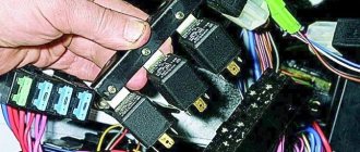
In the first case, the problem is solved quite simply. The main fuses are stored in the car's mounting block, and if any element of the system stops working, the first thing you should do is look there. When you open the cover, you will see a lot of fuses. However, if you carefully study the car’s electrical circuit on paper, it’s not difficult to figure out which fuse may be faulty. You can check the fuses for functionality using a special device. However, not everyone has it and therefore it is easier to replace the part with a known good one. If this is the problem, it will be resolved immediately.
In the case of a faulty generator, everything is somewhat more complicated. This device, which supplies the motor with high-voltage current, although it works on the principle of magnetic induction, is fraught with many unpleasant surprises. It is highly not recommended to attempt to repair a generator yourself. While there is even a slim chance of repairing the device, it is better to entrust this matter to specialists. A high-quality car service center will immediately determine the cause of all your problems and repair the faulty element of the electrical system in the shortest possible time.
Deciphering error codes
The first character is a letter and indicates a fault block:
- B - body;
- C - suspension;
- P — engine (ECM, gearbox);
- U - data exchange bus.
The second character is a number, code type:
- 0 — SAE (standard);
- 1.2 - OEM (factory);
- 3 - reserved.
The third character is a number, system:
- 1, 2 - fuel system;
- 3 - ignition system;
- 4 — reduction of exhaust gas toxicity;
- 5 - idle;
- 6 - ECU or its circuits;
- 7, 8 — transmission (automatic transmission).
The fourth and fifth characters are numbers, the error code itself.
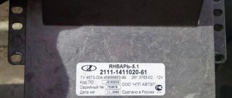
I decided to change the engine ECU from January 5.1.1 (2111-1411020-71) with firmware J5V13I02 with simultaneous injection to January 5.1 with pairwise parallel injection. As far as I understand from the information on various ECUs for our cars, even on the latest models of VAZ cars with 8-valve internal combustion engines (Granta, Samara) injection is pairwise-parallel. Therefore, I really wanted to switch to this type of injection and modernize my car.
To switch to pairwise parallel injection on the 2111 engine (1.5L 8 valves), in addition to another unit, it is also necessary to modify the wiring. Here's what I found about this conversion on the Internet. The first place I went was chiptuner.ru/content/changes/.
Weak points of VAZ injection wiring - A116.RU Kazan
Weak points of injection wiring of VAZ cars
Like any car, AvtoVAZ products have inherent flaws. The wiring of the engine control system is constantly being improved by the factory - sometimes in the direction of improving reliability.
Weak places where you need to look first.
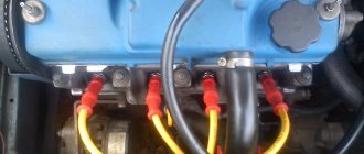
DPKV crankshaft position sensor connector. Not even the connector itself, but the wires that go to it. If the DPKV wire is not secured to the bracket on the lower bolt of the timing belt cover or with a clamp to the special eyelet of the cover, the wires break due to constant vibration and movements of the body relative to the engine. Wire strands under the insulation often break; from the outside, these wires appear intact. Also, a loose DPKV wire can touch a hot exhaust manifold - which causes the insulation to melt and the signal wires to short out to each other or to ground through the wire screen.
Speed sensor connector. Quite often, in the area of the speed sensor connector, the wires rub against the gearbox or are very bent. As a result of strong bending, the insulation of the wires is damaged. The speed sensor is located at the bottom of the motor - it quite often gets flooded with water from puddles. In addition, careless car owners periodically spill antifreeze or brake fluid, which can get on the damaged section of the wire. This causes copper conductors to oxidize and turn into dust.
Injector harness wiring. Quite often the wires are located on the fuel pipe attached to the fuel rail. Vibration causes the wires to fray and short to ground.
On 16-valve cars, the injector wiring is sandwiched between the filter and the cylinder head - it also gets frayed.
If you have something like this, don’t be lazy - do it like this in advance - correctly.
Wiring individual ignition coils on 16-valve engines. It rubs against the cylinder head or against the radiator pipe clamp in the area of the air filter housing - it’s very crowded there. If the signal wire is shorted to ground, the coil melts in the well.
Fastening the mass of the injection wiring.
In 2114, these are two brown wires that go under the tunnel for supplying warm air to the rear seats, somewhere under the carpet and sound insulation. Inside, the place of contact with the body may be well painted. Or the fastening nut or self-tapping screw (!) may become loose. In any case, it is advisable to separate these two brown wires and secure them at two different points to minimize the impact of the fan on the power supply to the control system (let me explain, if when you turn on the fan the machine responds quickly to this, you need to do this).
In 2110, the ground mount is located on a bracket under the panel in the area of the driver’s right foot. Often the nut 10 is not tightened. In addition, there is very poor contact between this bracket and the sternum of the body - the bracket is attracted by a nut to the body through the sound insulation layer. Poor contact with the sternum greatly affects the behavior of the temperature arrow on the instrument panel. The panel beeps, the arrow goes off scale - but the temperature is normal. Europanels 2112 suffer from this.
The control system power contact is on the positive terminal of the battery. Must be secured with a SEPARATE bolt to the terminal. Often attached under the clamping nut of the terminal, or many different types of music or alarms are hung on this pin.
Coolant temperature sensor wiring. The air filter housing often lies on the sensor connector and breaks short wires. If the fan is constantly spinning, look there!
The canister valve connector on Kalina - the valve is attached to the back of the air filter housing - very often the wire comes off at the root.
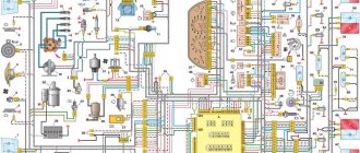
VAZ 2114 injector wiring diagram
The second ends of the black wires are also brought together to points connected to ground. In this case, the pads 12 are connected to the washer pump, and the wires connected to pumps 13 and 14 are connected to the corresponding solenoid valves. The Soldering Iron site exists only through advertising, so we would be grateful to you if you add the site to the list of exceptions.
A – block of headlights and headlight cleaners VAZ; B – cigarette lighter; B - VAZ mounting block, instrument cluster, VAZ ignition switch, windshield wiper and other electrical equipment components for blocks with a different number of plugs - the numbering order is similar; G – relay for turning on the rear fog light; D – alarm switch; E – gear motors for power windows and gear motors for locking door locks; F – interior lamp.
Electrical diagram of VAZ-2112
Designations: 1 – Headlight, 2 – Klaxon, 3 – Main radiator fan, 4 – Starter, 5 – Battery, 6 – Generator 2112, 7 – Gearbox limit switch (reverse), 8 – Actuator in the front passenger door, 9 – Power window enable relay, 10 – Starter relay, 11 – Heater fan, 12 – Electric heater partition drive, 13 – Main pump, 14 – Washer reservoir sensor, 15 – Driver’s door actuator, 16 – Front passenger window selector, 17 – Unlock button fifth door, 18 – Heater fan resistance unit, 19 – Main wiper motor, 20 – Driver’s window lift selector, 21 – Front passenger’s window lift motor, 22 – Central locking, 23 – Exterior light switch, 24 – Brake fluid leakage sensor, 25 – Pump additional, 26 – Driver's window lift motor, 27 – PTF on indicator, 28 – PTF switch, 29 – Dashboard, 30 – Heated glass on indicator, 31 – Heated glass switch, 32 – Steering column selector switch, 33 – PTF relay, 34 – Ignition switch, 35 – Main fuse block, 36 – Illumination of heater controls, 37 – Hazard warning button, 38 – Heater control controller, 39 – Glove compartment lighting, 40 – Glove compartment lid end cap, 41 – Cigarette lighter, 42 – BSK – display unit, 43 – Ashtray illumination, 44 – 12V socket, 45 – Instrument lighting switch, 46 – Actuator in the right rear door, 47 – Right rear passenger window selector, 48 – Clock, 49 – Right rear passenger window motor, 50 – Brake limit switch (closed – pedal is pressed), 51 – Left rear passenger window motor, 52 – Left rear passenger window selector, 53 – Actuator in the left rear door, 54 – Turn signal, 55 – Handbrake limit switch (closed – handbrake on), 56 – Rear wiper motor , 57 – Navigator's lamp, 58 – Interior lamp, 59 – Temperature sensor in the heater, 60 – Limit switch for the open front door, 61 – Limit switch for the open rear door, 62 – Trunk light, 63 – Rear optics (on the body), 64 – Rear optics (on the fifth door), 65 – License plate illumination.
The letters indicate the terminals to which it is connected: A – Front speaker on the right, B – Radio, C – Injector harness, D – ESD diagnostic connector, D – Front left speaker, E – Diagnostic connector for the heater controller, G – Rear right speaker, W – Rear left speaker, I – BC connector, K – glass heater thread, L – fifth door actuator, M – Additional brake light.
Wiring diagram VAZ-2112 injector 16 valves - full view
VAZ 2115 | Checking and replacing injectors
Signs of injector failure may include:
– difficult engine starting;
– unstable engine operation;
– the engine stalls at idle;
– reduced crankshaft rotation speed at idle;
– the engine does not develop full power, insufficient engine response;
– failures in engine operation when the vehicle is moving;
– increased fuel consumption;
– increased content of CH in the exhaust gases.
You will need: a 5-point hex key, a flat-blade screwdriver, a 17-point key (two), an autotester.
1. Disconnect the connecting block of the injector wiring harness and the engine harness by pressing the lock.
2. Perform an initial check of the injector windings. To do this, connect the ohmmeter to the contacts of the pads one by one.
The block has five contacts: four for supplying a control signal to the injectors and one common “+12 V” (a crimson wire with a black stripe is connected to it).
3. In turn, connect the four control contacts to the common contact and measure the resistance in each case. It should be 11–15 ohms. If in one or more measurements the resistance value differs from the specified value, the tested injectors or their wiring harness may be faulty.
4. For a more accurate check and replacement of injectors, remove the fuel rail from the car (see “Removing and installing the fuel rail”).
5. Use a screwdriver to pry off the spring retainer of the injector...
6. ...remove the clamp...
7. . and remove the injector from the fuel rail. Remove the remaining injectors in the same way.
8. To identify a faulty injector, connect an ohmmeter to the injector contacts. It should show a resistance of 11-15 ohms. If the winding resistance is not normal, replace the faulty injector, as it cannot be repaired.
Check the injector for the shape of the sprayed fuel spray and for leaks at specialized service stations, since such a check directly on the car is very fire hazardous.
The injectors of the VAZ-21126-00 engine of the VAZ-2170 Lada Priora car have an original design and are not interchangeable with the injectors of VAZ injection engines of other models. Buy new injectors with exactly the same markings.
9. Whenever removing injectors, be sure to replace the O-rings on all injectors on the ramp side. Using a screwdriver, carefully pry the edge of the ring...
10. ...remove the sealing ring from the injector...
11. ...and similarly remove the ring from the sprayer side.
12. If you are installing old injectors, carefully wash their nozzles with solvent or carburetor cleaner.
Install new O-rings carefully, without using any tools, after lubricating them with engine oil.
The sealing rings on the injectors are identical to other rings installed on early VAZ models with fuel injection systems and are interchangeable with them.
13. Before installing the injectors, lubricate the O-rings with engine oil or WD-40.
14. Install the injectors in the reverse order of removal, securing them to the ramp with clamps, after tightening them a little.
15. Having installed the fuel rail, connected the fuel line and connected the wiring harness block, secure the minus terminal on the battery, turn the ignition key 3-4 times to position “I” (ignition) at intervals of 2-3 s between turns on and check for leaks pipe connections and injector seals.
16. Install all removed parts in the reverse order of removal.
The VAZ-2114 wiring diagram has been implemented in the simplest possible way. The function of the wire transmitting the negative power pole is performed by the car body. This scheme is used in most modern cars. There are no complex components in the electrical wiring design; every driver can perform independent maintenance and repairs. The main thing is to be able to understand electrical circuits. You don’t need to know by heart all the wires and which specific node they are responsible for. You must be able to navigate complex networks of wires.
A few words about the procedure for working with wiring
At the end of today’s article, we’ll look at exactly how you should proceed if you want to change the wiring. As an example, let's take standard models of the VAZ brand - 2110, 2109 and the like. So, to competently work with car data electronics you will need:
- First, prepare for repair procedures. The implementation of this goal lies through:
- Purchasing the required wiring and devices;
- Search for the necessary connection diagrams;
- Selection of auxiliary tools: harnesses, fasteners, gloves for work, etc.
- After this, acting according to the diagrams of the currently installed electronics, we completely remove it. Naturally, before this you need to turn off the engine, disconnect the battery and put on gloves;
- Then the actual replacement of the VAZ wiring begins. Here you also need to act taking into account the connection diagrams. First of all, we connect the injector wiring according to the principle “from the oldest element to the youngest”. Next, we connect the main wiring outputs (ECU contacts) with the current source, and at the end we connect other electronics.
Of course, the noted procedure is only generalized, but, in general, compliance with it and compliance with the described rules for working with car wiring is the key to the success of such repairs. We hope that today's material was useful to you and provided answers to your questions. Good luck in maintaining and operating your car!
Dear customers, in order to avoid errors when sending the 5 pin connector (contacts) with the wires of the mating part of the injector wiring harness, which is one of the elements of the controller harness, in the “Comment” line indicate the “female” or “male” connector, your car model, year of manufacture .
Connector with wires for connecting to the injector wiring harness with 5 pins, used in VAZ 2108-099, VAZ 2110-2112, Lada Samara, Kalina, Priora, NIVA, Chevrolet Niva cars and their modifications. Can be used to make your own cable or other. The contacts are already crimped onto the wires (wire length 100 mm) and inserted into the connector. Can be installed on a car.
Key Features
The main feature of the VAZ-2114 wiring diagram is that it is necessary to supply power to all components that provide fuel injection:
- Electric fuel pump.
- Injectors in the fuel rail.
- Sensor system.
Power is also supplied to the electronic control unit and ignition system. Moreover, on 8-valve engines, only ignition modules were installed, which, in essence, are a switch with built-in coils (there are two in total). But on 16-valve engines, one coil was installed for each spark plug. This scheme is more advanced, since if the coil fails, only one cylinder will fail.
The entire car is based on the design of its predecessor, the VAZ-2109. The body shape is the same, the suspension, ignition and fuel supply elements used, even the rear lights are the same. But there are significant differences in the design of the engine and gearbox. The new europanel looks much more attractive. It uses more attractive sensors and other devices.
Car electrical wiring design
The general wiring diagram of the VAZ-2114 can be divided into several components:
- External lighting system.
- Ignition system.
- Fuel supply.
- Engine control (sensors, actuators and ECU).
- Starting the engine (starter).
- Power (battery and generator).
- Additional equipment systems - wipers, washer, heater, heated mirrors, seats and windows, cigarette lighter, etc.
Absolutely all circuits that are connected to the battery are protected by fuse links. They are installed in the mounting block under the hood (as on its predecessor, the VAZ-2109).
Switching occurs using electromagnetic relays. They allow you to get rid of the flow of large current through the buttons when turning on powerful consumers. The reason is that when direct switching of high currents occurs, the buttons are destroyed and the contacts burn. In this regard, electromagnetic relays are much more reliable.
Where is the diagnostic connector located?
On different cars of the VAZ family, the socket is located in different parts of the car. Let's look at a few models as an example:
- on the VAZ-2112 , as on the 2110 , as well as the 2111 , the socket is located to the right of the driver’s seat, immediately under the column;
- on models 2108 , 2109 and 21099 , the socket you need is located under the glove compartment, on a special shelf;
- on cars with a europanel it can be found in the center of the console, near the cigarette lighter. A special decorative cover is used to disguise it;
- Lada Kalina cars the connector is near the gear shift lever, it is also hidden under a special cover;
- On a Lada Priora, look right behind the glove compartment, on the wall.
VAZ 2110
Engine starting system
The wiring diagram of the VAZ-2114 (injector and carburetor if in the power system) must have a starter. It helps the engine start. In this case, the battery acts as a power source.
- Stator winding (fixed part).
- Rotor winding (excitation).
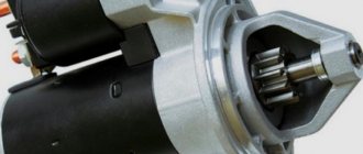
- Bendix - designed for mechanical connection of the starter rotor and the flywheel crown on the crankshaft. Consists of a drive fork, overrunning clutch and gear.
- Solenoid relay - drives the bendix and power contacts.
- Covers, brush assembly and other parts.
How the injector wiring should work, how to connect it yourself
When deciding to make major modifications to their car, or restoring it after serious breakdowns, many motorists are faced with the need to replace the wiring. In the design of any car, it is possible to replace either the under-hood wires, mainly coming from the injector, or the interior electronics that ensure the operation of application devices. In today’s article we will look at the features of repairing and replacing both types of wiring, taking VAZ cars as an example. Interesting? Then be sure to read the article below to the end.
How does a starter work?
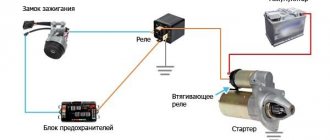
The starter is powered directly from the battery - a wire goes from the upper terminal of the solenoid relay to the positive terminal of the battery. The launch system works according to the following scheme:
- When you turn the ignition key, power is supplied to all components of the fuel system, the ECU.
- When the key is set to the “Start” position, power is supplied to the control output of the traction relay.
- The pull-in windings create a magnetic field, which causes the core to move.
- The power contacts close and the rotor begins to rotate.
- At the same time, the Bendix moves along the rotor axis, and the gear engages with the ring gear on the flywheel.
- The crankshaft begins to rotate, fuel is injected into the combustion chambers and high voltage is supplied to the spark plug electrodes.
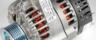
Generator design
The second power source of any car is the generator. It is necessary to power all consumers when the engine is running. The generator consists of the following parts:
- Rotary excitation winding.
- Slip rings on the rotor.
- Bearings.
- Front and back covers.
- Stator winding.
- Voltage regulator.
- Pulley with impeller.
- Diode block.
- Capacitor.
How does a generator work?
When the engine is stopped, the rotor winding is powered. Therefore, there is a magnetic field around it. But since the rotor does not rotate, the field is stationary. Therefore, one of the mandatory operating conditions of the generator set is not met - the magnetic field must be constant and moving. All conditions are met only when the starter begins to spin the crankshaft. In this case, the generator generates voltage supplied to the battery.
But the design feature of any car generator is that it produces alternating current. Moreover, three phases appear at the output, and alternating direct current is needed to power all consumers. Otherwise, all the sub-panel wiring of the VAZ-2114, the diagram of which is presented below, will simply burn out.
To rectify alternating current, a block of semiconductor silicon diodes is used. The design of a generator with three phases at the output is used for one simple reason - there is much less ripple. A capacitor is installed at the output of the rectifier - with its help it is possible to get rid of the entire alternating component of the current.
Voltage regulator operation
But there is one huge problem - depending on the crankshaft speed, the generator can produce voltage from 10 to 30 Volts, and such a variation is unacceptable. Therefore, it is necessary to stabilize the voltage at the same level - 12 V. In fact, of course, the generators produce a little more - 13.6-14.6 V. Only in this case will the battery be charged normally. You can stabilize the output voltage, but the problem is that the current consumption is very high.
And the zener diode must have considerable dimensions and, accordingly, cost. But it is much easier to stabilize the power supply to the rotor winding. If the voltage applied to it is stable, then the magnetic field will not change under any circumstances. This action is carried out using a voltage regulator. The maximum current consumption of the excitation winding is no more than 2 A. Structurally, the regulator is combined with a brush assembly.
Electronic control unit
The wiring diagram of the VAZ-2114 ECU turns out to be very complex, since a large number of sensors and actuators are connected to it.
- Housing made of plastic and metal.
- At the heart of the circuit is a microcontroller.
- Sensors are connected to the microcontroller inputs through matching devices.
- Signal amplifiers, electronic keys and relays are connected to the controller outputs.
The microcontroller allows you to send signals to the actuators, depending on how the engine is operating. The ECU memory contains the algorithm for the operation of all systems. Moreover, the wiring diagram of the VAZ-2114 (injector) 8 valves differs from the V16, since a little more parameters are needed to control the engine.
Control system sensors
VAZ-2114 cars use several sensors that are connected to an electronic control unit. They affect fuel injection and ignition timing.
The system consists of the following sensors:
- Throttle position.
- Crankshaft positions.
- Phases (camshaft position).
- Speed (located on the speedometer cable).
- Air flow. A MAP sensor can be used instead.
- Pressure.
- Detonations.
- Oxygen.
All these reading devices adjust the supply of the fuel mixture to the combustion chambers and the ignition timing. The wiring diagram for the VAZ-2114 (injector) with a description is given in the operating and maintenance instructions for the vehicle. There you can also learn how to perform troubleshooting yourself; the document also lists the main symptoms of breakdowns.
Did you like the article? Follow our channel for new ideas of useful car tips. Subscribe to us in Yandex.Zen. Subscribe.
The VAZ 2114 (in the factory classification - Samara-2) is built on the VAZ 21093 platform and is an improved version of it. The interior features a new instrument panel, a new steering wheel, an adjustable steering column, power windows and a new heater. Improvements affected the electrical part, which was reflected in the car's wiring.
Pinout of diagnostic connector for VAZ cars
VAZ cars have a fault diagnostic system that allows you to read and decipher error codes. Most VAZ-2110 cars have an old type “January-4” controller installed. The activation of “CHECK ENGINE” is considered a malfunction detection signal. Troubleshooting in such a controller is simple - error codes are calculated starting from the number 12 and ending with 61. For more modern VAZ models, ELM-327 electronic adapters with the OBD-II program are suitable.
Features of the new model
The electrical wiring of the VAZ 2114 has a different design than its predecessor:
- Inside the car;
- In the engine compartment;
- In the rear of the body.
For reference: initially the car was equipped with a 1.5 liter eight-valve engine of the VAZ-2111 model with an injection power system. Later, the automaker replaced it with a 1.6-liter VAZ-11183-1000260 environmental class power unit that meets Euro-3 requirements.
The new engines were equipped with a more powerful ignition system, as a result of which the wiring diagram of the VAZ 2114 to the injector had some peculiarities.
- A wiring harness was added to connect to the terminal of the ignition module, which supplied impulses to the spark plugs;
- A wiring harness has been added for connecting to the electronic switch;
- Wiring has been added to connect the adsorber valve to the injection system controller.
For reference: there is a misconception that the ignition module replaces the coil. In fact, the ignition module has 2 coils and 2 switches at once. The first coil supplies an impulse to the 1st and 4th cylinders, and the second - to the 2nd and 3rd cylinders.
The wiring for the VAZ 2114 has undergone changes not only due to the addition of new electronic devices, but also due to the automaker's further plans to modernize the functionality of the car.
- It is possible to connect heated exterior mirrors;
- It is possible to install heated front seats;
- It is possible to install front fog lights, etc.
Caution: When installing fog lights, the requirements of GOST R 51709-2001 must be observed. In particular, adhere to the rules set out in paragraph 4.3.12, which states that the fog lights are activated only when the side lights are turned on, regardless of whether the headlights are turned on.
Engine compartment
The first thing that owners of a carburetor power system pay attention to is the modified wiring diagram of the VAZ 2114 to the injector.
To operate on a lean mixture, the vehicle is equipped with:
- Forced fuel injection system directly into each cylinder;
- Installation of an increased power ignition system on the vehicle;
- Self-learning ECM - electronic engine control system.
For reference: a feature of EURO 3 standards is the low content of unburned fuel components in the exhaust gases. To this end, the car's fuel system reduces the amount of gasoline in the air-fuel mixture, compensating for this by better filling the cylinders due to forced fuel injection.
To ignite a lean air-fuel mixture in the engine cylinders, it is necessary to provide a more powerful spark at the moment when the piston is at TDC (top dead center).
This is realized by installing an ignition module, the operating principle of which is implemented:
- The generator produces alternating electric current;
- It is supplied to the ECU, which converts it to direct current;
- From the control unit, current is supplied to the windings of the ignition module coils;
- High voltage is generated in the secondary winding (according to the law of induction) of the coils;
- It is supplied to the spark plugs at the start of the ignition phase.
Advice: if you want to understand the operation of a car’s ignition and power system, it would be a good idea to watch video materials from a school physics course. Or find videos on automotive websites.
Vehicle interior
For the VAZ 2114 model, the automaker developed and installed a new dashboard, which differed from its predecessor:
- the absence of a glove compartment in the upper part - it was moved lower;
- new instrument panel;
- the advent of an on-board computer
For reference: the on-board (trip) computer gave readings about the outside air temperature, the voltage in the vehicle's on-board network, current fuel consumption, power reserve and other parameters.
The emergence of new electronic components has led to a change in the wiring diagram of the VAZ 2114 panel.
- a wiring harness with a connector for the on-board computer was added;
- an outside air temperature sensor has appeared, installed in front of the radiator;
- The voltmeter relay appeared.
In addition, a wiring harness was added to the front door panels, which were equipped with electric windows.
Pinout of the VAZ 2110 injector plug
Listen, what program do you use?
the one they have on their website? Added after 11 minutes 28 seconds:
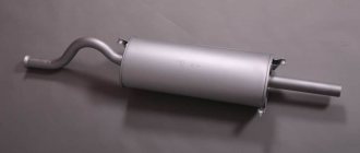
Anyway, I figured out my problem! I bought engine compartment wiring at a disassembly shop for 500 rubles in a bad condition and in just 6 hours, using a soldering iron and some mother, I made one perfect one from two dead harnesses. but the car still started, and after a few more hours of dancing around the car with a tambourine and a multimeter, it was found out that the recently replaced MZ had failed, and it seemed to have burned out from a short period of time. By the way, after the muffler ruptured, fuel consumption dropped sharply by 4 liters in the city. Can there be high consumption due to a clogged muffler? Or was it the wiring that was at fault?
Today the author came across the SAME problem - VS, 100% not sewn, shorted control of injectors 1-4, absorber, FIRE.. At first I thought that the pressure had dropped, because... The engine stalled smoothly at first, then after a couple of minutes of torment it began to work longer, but if it stalls, then the next starts with pops.. then I realized that there were problems with the ignition - the ignition or the lock was nonsense - although the errors were directed towards the wiring. We check the spark - chaotic, weak. Changed MZ - OK! The motor came to life.
Added after 1 minute 40 seconds:
The owner didn’t touch the wiring, he doesn’t even open the hood, so the MZ died a natural death for the author of the topic..
Added after 13 minutes 34 seconds:
In addition, I wanted - as happens with the mass air flow sensor. 10ka dragged along. BOSH1.5.4 E0. When I press the accelerator, the engine almost stalls. From the diagnostics, the TPS is 0.460 and rises smoothly without jerking, the mass air flow sensor at rest is 0.996! When the engine is running at idle, there are minor interruptions as if there were air leaks, but from the diagnostics everything is more or less normal - air consumption is 9 kg - + 0.5 (cannot be checked at rpm It turned out that there were jumps from 20kg to 40kg due to the shaking of the engine at the time of increase), UOS 13-19g, speed 800-900rpm, IAC 40-50sh. We tried to turn off the mass air flow sensor to make sure in emergency mode that it was not the mass air flow sensor... and the engine also does not gain momentum. Pressure 3.5 in the wall. The marks were checked 3 times, including the encoder, and the DPKV was changed because shot at the blowers (the MZ was checked and replaced with a new one), the wiring was checked, the controller was changed to January 5.1.1 and the same BOSCH - still the same. They removed the Siemens forces - there was sand, they removed them, checked them with similar BOSCHs, only new ones, everything was fine. In general, they changed everything except the mass air flow sensor, because... in emergency mode, nothing changed (although my January works faster when switched off than with the mass air flow sensor), but that was exactly the problem - the owner of the car said that it seemed like it had been washed.
Source
Troubleshooting electrical problems
During the operation of the vehicle, problems may arise due to malfunctions of electrical components.
- at the operation of the power unit, preventing it from developing its rated power;
- on the operation of devices, not allowing control of engine systems and other components;
- on the operation of lighting devices and comfort mechanisms (heating systems, interior lighting, window lifts, etc.)
Ignition system malfunctions
The main signs of a malfunctioning ignition system are:
- Difficulties in engine operation when accelerating the car;
- Loss of engine power during operation;
- Unstable or erratic idle;
- Malfunction of one or more cylinders.
Do-it-yourself troubleshooting should begin by checking sparking.
- Turn on the ignition;
- Remove the wire tip from the spark plug of the first cylinder;
- We bring it to the metal part of the motor at a distance of 4-5 mm;
- Turn on the starter;
- Let's see if a spark jumps between the wires;
- Similarly, we check the wires from spark plugs 2, 3 and 4 of cylinders.
Advice: If the spark discharge was stable in all cases, then the reason for the interruption in engine operation lies in the spark plugs. If there was no spark, the cause of the failure should be sought in the primary circuit from the generator to the ignition coil.
The search starts with:
- Directly ignition coils;
- Ignition module;
- ECU - on cars with VAZ-11183-1000260 engine
To check the ignition coil, you need to use a tester, with which you should measure the resistance of the primary and secondary windings.
Advice: If the readings obtained do not correspond to the data given in the car's passport, then the coil must be replaced. The probable cause of coil failure is a breakdown in the winding.
The ignition module is also checked using a tester. To do this, measure the resistance at its paired high-voltage terminals of the ignition module. The resistance should correspond to 5.4 kOhm.
Advice: if the cause of engine interruptions lies in the ignition module, then it needs to be replaced. The asking price is no more than 1000 rubles.
Basic tips for working with automotive electronics
Let’s immediately agree that installation, removal and any other work with car wiring are the most complex operations, which are taught in secondary specialized educational institutions. This article is for informational purposes only on working with the electronics of VAZ models and contains solely a description of the basic aspects of these procedures, so it will not be possible to learn from it all the intricacies of wiring repairs. Familiarization with these lies only through long and hard work associated with work practice in the field of automobile repair.
Returning to the main topic of today’s material, it would not be out of place to note: even a person without special skills in this path has the opportunity to install the wiring of any car with his own hands. However, for proper implementation of all procedures it is extremely important:
- Have the necessary diagrams that connect the wiring to a specific engine and dashboard. You can find them either when purchasing certified parts or the machine itself, or on the World Wide Web;
- Know the basics of working with automotive electronics, which we will get acquainted with in this article;
- Find free time, a small amount of tools and a place for repair work.