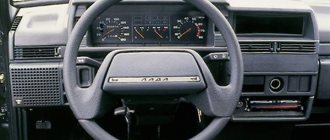
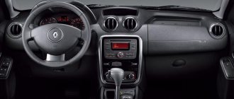
Europanel for VAZ 2114 is the best option for car tuning.
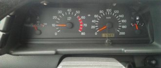
After all, even modern models of this series have an old-style panel installed, which has a number of disadvantages, namely:
- the low quality of the plastic from which the “tidy” is made fills the car with a characteristic squeak literally after 500-1000 km;
- the view of some of the instruments is blocked by the steering wheel;
- at night, the dashboard is reflected on the windshield, which distracts the driver;
- The air ducts installed in the body of the torpedo are poorly fitted and, as a result, problems arise with the ventilation of the car.
These and some other disadvantages push owners of almost new cars to replace their original panel with a Euro panel VAZ 2114. It should be noted that on models with an injection engine such a panel is installed directly at the manufacturer.
Euro torpedo VAZ 2114: advantages and disadvantages
The Europanel is perfect for installation on a VAZ 2114 and does not require additional alteration or adjustment.
Its quality significantly exceeds that of the panel provided by the factory, due to such points as:
- more modern design;
- better quality material (plastic);
- availability of built-in VDO devices (with internal lighting);
- presence of a digital odometer;
- original design of signal lamps;
- the presence of several additional compartments for storing small items;
- well-equipped air duct, etc.
In addition, the VAZ 2114 Europanel allows the driver, if necessary, to connect various additional sensors (for example, levels of antifreeze or windshield washer fluid or open doors).
Of course, the europanel has some disadvantages, including:
- not full amplitude (does not reach the edges of the slots) and tight movement of the air damper control levers;
- poor adjustment of rods and cables, etc.
Despite the existing shortcomings, installing a Europanel changes the appearance and comfort of the VAZ 2114 interior so much for the better that car drivers are increasingly resorting to this procedure.
Recent comments
- admin to the post differences between 8v and 16v controllers using the example of January 7.2 8v and Bosch 7.9.7 16v
- admin to post Useful information
- admin to post Atomic soft
- admin to the post Answered questions (comments) over the past months
- admin to the entry Pinout of the connection block SUD M7.9.7./January7.2 to the interior wiring of the Europanel (VAZ 2114)
- admin to the entry Chiptuning - About the table of monitoring stations and control centers (for dummies)
- admin to the post Answer to a question about Atomic Tune 2.8.8
- daser on Angel Eyes
- Kirill on the entry Pinout of the connection block SUD M7.9.7./January7.2 to the interior wiring of the Europanel (VAZ 2114)
- Anonymous to the post Answered questions (comments) in recent months
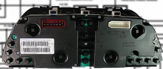
Europanel: standard equipment
With a total weight of 17 kg, the panel has overall dimensions (in cm) – 170x90x100.
The package includes all the elements necessary for quick installation and further operation:
- Instrument panel (qty. - 1 pc.).
- Set of devices (qty. - 1 pc.).
- Under-panel wiring harness (qty. - 1 pc.).
- Central console (qty. - 1 pc.).
- Floor tunnel (qty. - 1 pc.).
- Control unit for the heater (qty. - 1 pc.).
- Top cover for the glove compartment (qty. - 1 pc.).
- External lighting switch (qty. - 1 pc.).
- Rear fog light switch (qty. - 1 pc.).
- Heating switch for rear window (qty. - 1 pc.).
- Set of plugs for switches (qty. - 4 pcs.).
- Heater air duct deflector (qty. - 5 pcs.).
- Cigarette lighter (qty. - 1 pc.).
- Metal frame (quantity - 1 piece).
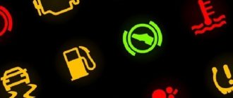
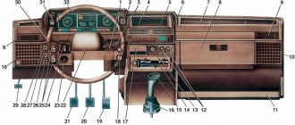
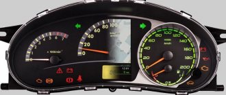
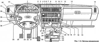
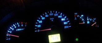
Main instruments on the dashboard
Speedometer
Engine piston YaMZ-651.10 composite assembled EURO-4
Indicates the approximate vehicle speed (in km/h).
Odometer
Serves to display the total mileage of the vehicle (in km).
Trip counter
The daily mileage counter allows you to determine the vehicle mileage for a specific period of time (for example, during the last trip). To reset the daily mileage counter, use a special reset button.
Note : The trip counter can only be reset when the vehicle is stationary.
Tachometer
Shows the approximate engine speed (in revolutions per minute). To obtain the rotation speed value, you need to multiply the number on the scale that the arrow points to by 100.
The red zone (the area of the scale shaded in red) means the engine is operating at a high frequency, which is dangerous for the engine.
ATTENTION: Do not allow the engine to operate in such a way that the tachometer needle is in the red zone (more than 6000 rpm).
Engine temperature gauge
The transition of the arrow of this indicator to the red zone of the scale indicates overheating of the engine. In this case, check the operation of the thermostat and electric fan of the cooling system.
ATTENTION: Do not allow the engine to operate in overheating mode (over 110°C).
Fuel level indicator
When the ignition is turned on, this indicator displays the approximate amount of fuel in the tank. If the fuel in the tank is almost running out (less than 7-9.5 liters left), the arrow approaches the “0” value on the scale and the corresponding light indicator lights up warning of the need to refuel. In this case, it is recommended to refuel as soon as possible.
Econometer
This indicator is intended to help the driver choose the most economical engine operating mode. The econometer scale is divided into two zones - white and yellow. The white zone corresponds to the economical mode, the yellow zone to the high fuel consumption mode.
Left steering column switch
The left steering column switch is used to control the vehicle's lighting devices.
The following lighting modes correspond to the different switch positions:
1 — direction indicators are off; The low beam headlights are on if the exterior lighting switch is set to the appropriate position.
2 — left turn indicators are on (non-fixed position).
3 — left turn indicators are on (fixed position).
4 — right direction indicators are on (non-fixed position).
5 — right turn indicators are on (fixed position).
6 — (for yourself), turning on the high beam headlights regardless of the position of the external lighting switch (non-fixed position).
7 - (from yourself), turning on the high beam headlights if the exterior lighting switch is set to the headlights on position (fixed position).
Right steering column switch
The right steering column switch is designed to control the windshield wipers and washers.
The different switch positions correspond to the following operating modes of the windshield wipers:
1 - windshield wipers and windshield washer are turned off.
2 — activation of intermittent operation of the windshield wipers (non-fixed position).
3 — activation of intermittent operation of the windshield wipers (fixed position).
4 — activation of the first speed of windshield wipers (fixed position).
5 — activation of the second speed of windshield wipers (fixed position).
6 — (pull), turning on the windshield washers (non-fixed position). At the same time, the windshield wipers are switched on.
7 — (from yourself), turn on the rear window wiper (fixed position).
8 - (from yourself), additional activation of the rear window washer (non-fixed position).
Hood
To open the hood, you need to pull the lever located under the instrument panel on the left side, which will raise the hood slightly. Through the resulting gap, press the lever (1) of the safety hook and lift the hood. Install the stop (2) into the hood slot, as shown in the photo.
To close the hood, lower it to a height of 20-30 cm until it is completely closed and release. Make sure that the hood lock has engaged - you should hear a characteristic click.
Note : Before closing the hood, make sure that the safety hook (3) rotates without jamming and returns easily to its original position.
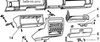
How to install europanel 2114?
All actions are performed in the following sequence (for greater convenience, you can remove the seats and column):
- The old panel is removed.
- The europanel is “attached” to the installation site and screwed (together with the column).
- The central frame is installed.
- The stove control is screwed on.
Please note that even new VAZ 2114 cables may not be suitable for installation. In this case, you can make them yourself.
- Wiring is being laid.
- The “beard” and side pads are installed in the legs.
Installing the panel will not take much time, since it does not require special adjustment to the interior features.
VAZ 2109 wiring diagram
The VAZ 2109 car has remained one of the most popular in the country for many years. Not just popular, but also prestigious. In the social hierarchy, owners of nines were not much lower than owners of used Cadets and Jettas. One could argue with the reliability of the car, but since there was no alternative, the car filled the entire CIS and was even assembled using the hub method in Finland, but this has little to do with the 2109 model.
This is interesting: 10 ways that will save you from frequent car washing
Content:
Wiring diagram VAZ 2109
Like the entire car, the electrical equipment was not at the highest level, so owners of nines should know the VAZ 2109 wiring diagram thoroughly. To do this, we have provided the factory diagram in good resolution, which can be used with adjustments for changes made from time to time.
This is a diagram of the canonical nine with factory markings and explanations. In principle, the circuit is quite simple, but the electrical appliances themselves caused difficulties, the problems with which we will talk.
Basic problems with electrical wiring 2109
The biggest problem with the electrical equipment of the VAZ 2109 was the low quality of components and unsatisfactory build quality. Despite the fact that Togliatti traditionally blames suppliers for all mortal sins, in the end we have to take the rap, and as ordinary users, we should not be interested at all in why the spirals on the double-filament rear light bulbs constantly burn out. Also, in principle, we don’t care which factory made the housing for the fuse box - we only see the inadequate operation of the electrical equipment when pressing the brake pedal turns on the right turn.
And a lot of such examples can be given. If the factory is not confident in the quality of the components, then why install them on the car. Therefore, rhetorical questions only lead to unnecessary vibrations in the air, and do not solve the problem. The above problem with feet can be solved quite simply:
- the rear light cover is removed;
- the power terminals are disconnected from the trunk;
- the entire strip on which the lamps are mounted is unscrewed;
- The contact on the flexible board at the point of attachment to the lamp socket is checked.
Short circuits of the tracks of this board occur due to contamination of the contacts and tracks. Then the signal sent to the stop lamp can simply be redirected to the turn signal lamp. This can be radically solved by replacing the entire board with a new one, but the new strip will not last as long as we would like due to poor sealing of the lamp from inside the luggage compartment. It seems like a trifle, but we spend precious time solving trivial problems that are solved at the production level with the right approach, not the VAZ approach.
Improvements and correction of factory errors
In light of the above, a breakdown of the electronics control unit is very typical for the nine. The reason is very simple - its body simply allows water, dust and moisture in the form of condensation to pass through. Its very placement on the air supply shelf is not entirely clear, but there are also more significant disadvantages that can be eliminated with your own hands. The factory provided a tiny groove to drain water from the housing, but it constantly gets clogged, the housing fills with water, and the control unit slowly and surely dies. It is not cheap, so such negligence of the designers cannot be explained. There are two ways out of the situation - constantly clean the water drainage channel, or change the block at least once a year.
It is also worth paying attention to the fact that the power wiring on the bottom shelf of the radiator is constantly exposed to high temperatures. In addition, in this place it is in no way protected from water and dirt. This is also a difficult moment to explain. The category of wiring harness oversights includes the harness under the carpet next to the driver's seat. Moisture constantly accumulates there, and in order to remove it, you need to dry the floor, inevitably tugging on the rope. Of course, this problem cannot be solved on your own - the amount of work required to re-tighten all the wiring in the car is too large.
It is worth paying special attention to the power terminals on the generator. They very often become loose, heat up, spark and melt the wiring. But that's not the worst thing. The wires may short out, and it already smells burnt. Therefore, you should not be lazy, but check this unit as often as possible for tightness of the terminals.
Wire harness insulation 2109
No one will disassemble half a car for the sake of insulating the harnesses, but if necessary, you need to do this for your own safety. Using the diagram that we placed at the beginning of the article, all the work will not take much time, but you will be confident in the quality of the wiring insulation. For this you will need:
- Corrugated hose for electrical wires.
- Insulating tape.
- Wire cleaner.
Before wrapping old wiring in a sleeve, treat the wires with a cleaner, which is widely available in aerosol cans. Next, following the instructions and checking the electrical diagram, we proceed as follows:
- Disconnecting the battery
- Disconnect the terminals and remove the harness.
- We treat it with an aerosol.
- We carry out a visual check of the contacts.
- We lay the tourniquet in the corrugation.
- We fix and seal the entry points of the harness into the corrugation.
- We put the finished cable in place.
- Referring to the diagram, connect the terminals.
Particular attention should be paid to sealing the harnesses in places where they come into direct contact with water or hot surfaces. Also, when assembling, pay attention to the integrity of the pads and the condition of the contacts and terminals.
Thus, having spent very little time, we will save the wiring and get rid of unnecessary problems with short circuits. Keep an eye on the wiring, and good luck on the road!