Before replacing the oxygen sensor, you need to make sure that it is this that is causing the engine to malfunction: failures during acceleration, loss of power, increased consumption, engine tripping. To do this we need to check the oxygen sensor.
List of possible malfunctions of the lambda probe (oxygen sensor):
- heating not working;
- loss of sensitivity - decreased performance (how to repair the sensor (restore sensitivity)?).
As a rule, the death of a sensor is most often not recorded on a car if the cause is in the sensitivity of the sensor. But if there is a break in the sensor heating circuit, the on-board computer will instantly give you an error.
How to properly install a universal oxygen sensor?
1. Cut the new oxygen sensor wires to the required length.
IMPORTANT: The new sensor connected to your existing connector must be the same length as the old sensor with the original connector.
2. Cut the wire from the old oxygen sensor.
3. Strip the wires of the new sensor and connector from insulation by approximately 7 mm each.
4. Crimp the butt joints of the sensor and conductor with special pliers and cover with heat shrink tubing (size 22–16).
5. Apply hot air to the shrink insulation until the connections are tightly sealed.
General connection rules
Since 1999, cars have typically been equipped with zirconium or titanium oxygen sensors that meet certain standards regarding wire colors. The number of wires is usually four. Below are tables for both probes. In the vast majority of cases, to check you will need the first table - for zirconium sensors, but occasionally you can find titanium ones.
If, during reconciliation, it is revealed that the combination of colors in one of the columns of the table corresponds to the colors of the lambda probe wires of your car, this means that the probe is structurally designed this way, and the pinout should be done in accordance with these data.
Color combinations (zirconium probes)
Color combinations (titanium probes)
Tip for using the table:
- Check the oxygen sensor wires in your car.
- Compare their colors with the columns in the tables.
- If the colors completely match one of them, then this is exactly the design you have and you should build on it.
For example, your lambda probe is equipped with four wires of the following colors: beige, purple and two brown. The same combination is indicated in the fourth column of the first table. This means you have a zirconium device with the same wires and operating principle. Next, we look at the first column of the same table and see that the arrangement of the wires according to the diagram is as follows: the beige one goes to ground (minus), the purple one is responsible for transmitting signal data, and the two brown ones are needed for the operation of the heater. This way you can accurately identify the wires by their shades.
How to correctly connect the oxygen sensor wires by color?
1. Find out what wire colors are used on your old sensor.
2. Select the appropriate DENSO universal oxygen sensor. For all DENSO sensors there are two types of cable color combinations depending on the article number.
3. Connect the wires according to the data in the table below:
| Old (original) sensor | New DENSO sensor | |||||
| Original sensor type 1 | Original sensor type 2 | Original sensor type 3 | Original sensor type 4 | Original sensor type 5 | ||
DOX-010.
DOX-011.
DOX-012.
DOX-013.
DOX-015.
The original sensor has 4 wires with the following color combination: 2 white, black and gray. The DENSO oxygen sensor art. no. is suitable for your vehicle. DOX-0107. Therefore, the wires should be connected as shown in the picture below:
Option 2: - Black wire on the ECU - Gray wire - ground - White wires - “-” and “+” for heating the probe - polarity does not matter. In this case, the white “-” is thrown to ground, and the white “+” to the ignition switch, or to the battery through a relay or something like that. Then it turns out that 2 native contacts remain empty.
Lambda probe sensor pinout table
| Purpose | Color combinations for zirconium sensors. | ||||
| 1 | 2 | 3 | 4 | 5 | |
| Heater + | Black | Violet | White | Brown | Black |
| Heater - | Black | White | White | Brown | Black |
| Signal + | Blue | Black | Black | Violet | Green |
| Signal - | White | Grey | Grey | Beige | White |
| Purpose | Color combinations for titanium sensors. | |
| 1 | 2 | |
| Heater + | Black | Red |
| Heater - | Black | White |
| Signal + | Grey | Yellow |
| Signal - | Grey | Black |
What does a lambda probe consist of?
Posts 6
1 Topic by serega 32 2014-11-30 00:15:08
- serega 32
- New member
- Inactive
- Registration: 2014-11-29
- Messages: 5 Thanks : 0
- Car: VAZ 2109i
Topic: oxygen sensor connector is broken, how to connect by color? VAZ 2109
The connector has come off. How can I now connect the wires without this connector? Which wire goes to which? they are not there by color. Tell me who has encountered this!?
Added: 2014-11-30 01:15:08
I forgot to say, the car is a VAZ 2109i
2 Reply from Serg 2014-11-30 08:52:53 (2014-11-30 08:59:27 edited by Serg)
- Serg
- Lada2111.rf fan
- Inactive
- Registration: 2013-07-29
- Messages: 830 Thanks : 363
- Car: 2111 dwg 2114 year 2008
Re: oxygen sensor connector is broken, how to connect by color? VAZ 2109
Which side did the sensor or harness come off from? The connector has the letters ABCD
sensor A - C sensor output (gray and black) B - D sensor heater (usually white wires)
harness A - pink to ecu 28 leg B - pinkblack +12v heater power supply C - red and white to ecu 10 leg D - white to ecu
3 Reply from serega 32 2014-11-30 11:41:24
- serega 32
- New member
- Inactive
- Registration: 2014-11-29
- Messages: 5 Thanks : 0
- Car: VAZ 2109i
Re: oxygen sensor connector is broken, how to connect by color? VAZ 2109
Thank you. only there is no connector itself, just wires hanging. 4 from the sensor and 4 from the harness.
Publication date: January 16, 2022. Category: Automotive equipment.
Lambda probe (also called oxygen controller, O2 sensor, DC) is an integral part of the exhaust system of vehicles that meet EURO-4 environmental standards and higher. This miniature device (usually 2 or more lambda probes are installed) monitors the O2 content in vehicle exhaust mixtures, thereby significantly reducing the emission of toxic waste into the atmosphere.
If the DC is not operating correctly or if the lambda probe is disconnected, the functioning of the power unit may be disrupted, causing the engine to go into emergency mode (the Check Engine light will light up on the panel). To prevent this from happening, the car system can be outsmarted by installing a decoy.
Pinout Mikas 7.1 injector and carburetor
This block is designed to control internal combustion engines:
- ZMZ-4062.10—with gasoline injection and electronic control;
- ZMZ-409.10—with gasoline injection and electronic control;
- ZMZ-405.10—with gasoline injection and electronic control;
- ZMZ-4063.10—carburetor, with electronic ignition system;
- ZMZ-4061.10—carburetor, with electronic ignition system.
- UMZ-4213.10—with gasoline injection and electronic control;
- UMZ-420.10—with gasoline injection and electronic control.
The block is a multi-mode cyclic machine with an extensive program that provides registration and processing of information from the system sensors to control the actuating electric mechanisms of the engine. The block is implemented on the basis of an 8-bit microcontroller and on an imported element base, has a monoblock single-board design with a 55-pin electrical connector from AMP.
| 1 | white | Ignition coils 1 and 4 (KZ/1-4) Ignition control circuit. Creates excitation in ignition coils 1 and 4. |
| 2 | black White | Grounding the control unit. (General GNI) The contact is connected to the vehicle ground. The voltage at the contact relative to ground should be close to zero. |
| 3 | white/green | Fuel pump relay (FPR) Control of the fuel supply system relay. Turning on the ignition is a signal for the control unit to connect power (+12 V) to the fuel supply system relay. If there are no crankshaft position reference signals, the control unit turns off the relay. When the reference signals of the position of the k.v. are resumed. the unit turns on the fuel pump relay again. |
| 4 | blue/cyan | Additional air regulator* (РДВ/1) |
| 5 | Not used | |
| 6 | White black | Input signal from the mass air flow sensor “-” (MAF) |
| 7 | black/yellow | Input signal from the mass air flow sensor “+” (MAF+) |
| 8 | pink | Input signal from the camshaft position sensor “+” (DPRV +) |
| 9 | Not used | |
| 10 | Not used | |
| 11 | green/white | Knock Sensor Input Signal "+" (DD+) The signal is the voltage supplied to the control unit from the knock sensor to detect knock. The block adjusts the ignition timing depending on the level of detonation to extinguish it |
| 12 | White yellow | Power output of the throttle position sensor (TPS (power) |
| 13 | brown | L - diagnostic line (L - Line) |
| 14 | black | Control unit grounding (Common GNP) The contact is connected to the vehicle ground. The voltage at the contact relative to ground should be close to zero. |
| 15 | Not used | |
| 16 | pink/green | Nozzle 2(F/2) |
| 17 | orange | Injector 1 (F/1) Injector control. The voltage at these contacts is supplied through injectors connected to +12 V. When the ignition is on and the engine is not running, the voltage at the contacts is equal to the battery voltage. At idle, the charging system increases this voltage slightly. At higher engine speeds or greater engine load, the increased frequency and duration of the injector injection pulse causes a slight decrease in voltage compared to the idle voltage. |
| 18 | blue | Battery terminal 30 + 12 V ( 30 ) Provides constant +12 V power to the electronic unit, including when the ignition is turned off. The voltage comes through the fuse. |
| 19 | blue red | Common (Common GNO) The contact is connected to the vehicle ground. The voltage at the contact should be zero. |
| 20 | brown/white | Ignition coils 2 and 3 (KZ/2-3) Ignition control circuit. Creates excitation in ignition coils 2 and 3. |
| 21 | Not used | |
| 22 | pink/blue | Diagnostic lamp (LD) Control of the diagnostic lamp. The electronic unit provides ground for turning on the diagnostic lamp. With the ignition on and the engine not running, the lamp should light up for 0.6 s and go out, and the voltage at the contact relative to ground should be close to zero. When the lamp is turned on, this voltage matches the battery voltage. |
| 23 | Not used | |
| 24 | red/pink | Control unit grounding (General GNI) The contact is connected to the vehicle ground. The voltage at the contact relative to ground should be close to zero. |
| 25 | Not used | |
| 26 | yellow/black | Additional air regulator (RDV/2) |
| 27 | orange/white | Ignition switch, terminal 15 (15) “On” signal to the control unit from the ignition switch circuit. The signal does not power the unit, it signals to it that the ignition is on. The voltage is equal to the battery voltage when the ignition switch is in the ignition or starter position. |
| 28 | Not used | |
| 29 | Not used | |
| 30 | Red Green | Common sensors (General GNA) The contact is connected to the vehicle ground. The voltage at the contact relative to ground should be close to zero. |
| 31 | yellow/white | Control channel for the burn-in of the mass air flow sensor (burn-in of the mass air flow sensor) |
| 32 | Not used | |
| 33 | Not used | |
| 34 | orange/red | Nozzle 4(F/4) |
| 35 | yellow green | Injector 3 (F/3) see pins 16 and 17. |
| 36 | measles h/blue and | Input signal from CO adjustment potentiometer (PTSO +) |
| 37 | orange/green | Input+12V(12) |
| 38 | Not used | |
| 39 | Not used | |
| 40 | Not used | |
| 41 | Not used | |
| 42 | Not used | |
| 43 | blue/black | Output signal (logic level) to tachometer |
| 44 | white/pink | Input signal from intake air temperature (IAT) sensor |
| 45 | White blue | Input signal from the coolant temperature sensor (DTOHL) The electronic control unit sends a 5 V signal to the coolant temperature sensor, which is a thermistor. The sensor, also connected to ground, changes the voltage depending on the temperature of the coolant. |
| 46 | white/brown | Main relay (RGL) |
| 47 | Not used | |
| 48 | yellow/blue | Input signal from the crankshaft position sensor “-” (DPKV -) |
| 49 | white/blue | Input signal from the crankshaft position sensor (Dpkv+) The contacts provide the electronic unit with data on the speed and position of the crankshaft. With the ignition on but the engine not running, the voltage should be below 1V. As the crankshaft rotates, the voltage increases with increasing speed. |
| 50 | Not used | |
| 51 | Not used | |
| 52 | Not used | |
| 53 | green | Throttle Position Sensor + Input (TPS+) The input voltage of the throttle position sensor, which corresponds to actual changes in throttle position, varies from 0 to 5 V. Typically, the voltage at idle speed is below 1 V, and with the throttle fully open it is 4.4...4.7 V. |
| 54 | Not used | |
| 55 | Red Blue | K - diagnostic line (K-Line) This line communicates with diagnostic equipment (tester, stand, etc.) |
Types and versions of MIKAS-7 blocks
- "MIKAS-7.1"—for GAZ cars;
- "MIKAS-7.2"—for UAZ cars.
Designation of the MIKAS-7 block according to TU: 29ХK.3763-YY, where:
- X—even number for the block version with an immobilizer, odd number—without an immobilizer;
- X—number 1 or 2—for UMZ-XX engines;
- X—number 3 or 4—for ZMZ-XX engines;
- K—climatic version: k=7 for version “U-T”, no number for version “U”;
- YY—version number according to purpose: engine brand, control system configuration, vehicle type.
For example, the MIKAS-7.2 block has the following versions:
291.3763000-01—for UAZ-31625 with UMZ-4213.10 engine; 293.3763000-01—for UAZ-3159 with ZMZ-409.10 engine.
Table of pin number and what it is connected to
| № | Mikas 7.1/ 7.2 | Mikas 7.6 |
| 1 | Ignition coils 1, 4 | Ignition coil "A" |
| 2 | Control unit grounding | not used |
| 3 | Fuel pump relay. | Fuel pump relay |
| 4 | Auxiliary air regulator, circuit 1 | Additional air regulator (ADV), circuit A |
| 5 | Canister purge valve. | not used |
| 6 | Input signal from mass air flow sensor “-“ | Radiator Fan Relay |
| 7 | Input signal from mass air flow sensor “+” | Absolute Pressure Sensor (APTS) (+) |
| 8 | Entrance. Phase sensor "+" | not used |
| 9 | Speed sensor "+" | Speed sensor |
| 10 | Oxygen sensor 1 "-" | Oxygen sensor weight |
| 11 | Input signal from knock sensor “+” | Knock sensor (DS) |
| 12 | Throttle position sensor power supply | Absolute Pressure Sensor (APTS) (-) |
| 13 | L - diagnostic line | L - diagnostic line (L-Line) |
| 14 | Control unit grounding | General power |
| 15 | Shaper FVN1 | Oxygen Sensor Heater |
| 16 | Injector 2 | Injector 2 |
| 17 | Injector 1 | not used |
| 18 | Battery terminal 30 + 12 V | Battery terminal 30 + 12 V |
| 19 | General power | General power |
| 20 | Ignition coils 2, 3 | Ignition coil "B" |
| 21 | Shaper FVN3 | Additional air regulator (ADV), circuit C |
| 22 | Diagnostic lamp | Diagnostic lamp |
| 23 | Recirculation valve | Injector 1 |
| 24 | Common ignition wire | Common ignition wire |
| 25 | Air conditioner relay | not used |
| 26 | Additional air regulator, circuit 2 | Additional air regulator, circuit B |
| 27 | Ignition switch, terminal 15 | Ignition switch, terminal 15 |
| 28 | Oxygen sensor 1 “+” | Input Oxygen Sensor |
| 29 | Shaper FVN2 | Additional air regulator (ADV), circuit D |
| 30 | General sensors | Common sensor wire |
| 31 | Burning control channel for mass air flow sensor | not used |
| 32 | Fuel consumption sensor | not used |
| 33 | Secondary air relay | Oxygen Sensor Heater |
| 34 | Injector 4 | Injector 4 |
| 35 | Injector 3 | Injector 3 |
| 36 | Entrance. CO adjustment potentiometer | not used |
| 37 | Input +12V after the main relay | +12V after the main relay |
| 38 | PBS signal | not used |
| 39 | Oxygen sensor 2 "-" | not used |
| 40 | Air conditioner request | not used |
| 41 | Knock sensor 2 "+" | not used |
| 42 | Block programming permission | not used |
| 43 | Output, logical. Signal to tachometer | not used |
| 44 | Entrance. Intake air temperature sensor “+” | Intake Air Temperature Sensor (IAT) |
| 45 | Entrance. Coolant temperature sensor “+” | Coolant temperature sensor (DTOZH) |
| 46 | Main relay | Main relay |
| 47 | Pressure sensor power supply | Block programming permission |
| 48 | Frequency sensor "-" | Frequency sensor (DPKV) “-“ |
| 49 | Frequency sensor "+" | Frequency sensor (DPKV) “+” |
| 50 | Pressure sensor "+" | not used |
| 51 | Diagnosis of FVN | not used |
| 52 | Shaper FVN4 | CO adjustment potentiometer (RCO) |
| 53 | Throttle position sensor. Input "+" | Throttle Position Sensor (TPS) |
| 54 | Recirculation valve position sensor | not used |
| 55 | K - diagnostic line | K - diagnostic line (K-Line) |
Mechanical snag of the lambda probe (“screw-in”)
“Vvertysh” is a bushing made of bronze or heat-resistant steel. The inside of such a “spacer” and its cavities are filled with ceramic chips with a special catalytic coating. Due to this, the exhaust gases are burned faster, which, in turn, leads to different indicators of pulses 1 and 2 DC.
Important! Any snag is installed only on a working lambda probe.
A homemade lambda probe decoy, the diagram of which is presented below, is easy to manufacture. To do this you will need to prepare:
The blende is made on a processing lathe. If there is none, then you can contact a specialist by providing him with a drawing.
The resulting part is compatible with most exhaust systems of both domestic and foreign cars.
Installation of the lambda probe blende is carried out as follows:
- Lift the car onto the overpass.
- Disconnect the negative terminal on the battery.
- Unscrew the first (upper) probe (if there are two of them, then remove the one located between the catalyst and the exhaust manifold).
- Screw the lambda probe into the spacer.
- Reinstall the "advanced" sensor.
- Connect the terminal to the battery.
Healthy! Typically, mechanical blending of the second lambda probe is not performed, since this DC is protected by a catalyst and only controls its condition. The most sensitive is the first sensor, which is installed closest to the collector.
After this, the “Check Engine” system error should disappear. If this method does not work, you can use a more expensive deception.
Replacing the oxygen sensor
This small guide will be useful not only to owners of VAZ 2107 cars, but also to more modern tens and fourteeners. Please note that all repair work is best carried out on a lift or inspection pit. Do not forget that the catalytic collector is located in the exhaust gas system. If necessary, dismantle the engine protection of the VAZ 2107. Next, look for all the wires that relate to the oxygen sensor.
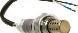
All clamps should be cut using wire cutters and the connectors should be disconnected. Moreover, it is advisable to thoroughly clean the one that remains on the machine from accumulated dust and dirt, since it will be used in the future. If the exhaust tract is hot, allow it to cool. Then, using a key with size “22”, unscrew the lambda probe. Screw the new device into place of the old one, tighten the nuts and connect the connection connector. The pinout of the oxygen concentration sensor is shown in the photo.
Do not lay wires too close to the exhaust pipe. They need to be secured with clamps to the elements of the cooling system. Finally, install engine protection on the VAZ 2107 and make a test drive to make sure the sensor is working. One of the problems that may arise during replacement is the sensor housing sticking to the exhaust pipe. In this case, penetrating lubricant can help (its price is about 70 rubles for a 200 ml container). If it does not help, then start the engine and warm it up. Try unscrewing the sensor while it is hot.
If this does not help, then let the system cool down, after which you heat only the sensor housing. You can even deliver several sharp but weak blows. And the very last method is to heat the body of the VAZ 2107 lambda probe to a high temperature and pour cold water over it. One of these methods should help to unscrew the oxygen sensor on the VAZ 2107. The price of a new device ranges from one to three thousand rubles.
Operating principle
The sensor's sensing element can be found in the exhaust gas stream. The electrolyte, which is located in one of the exhaust gas streams, is heated to a high temperature (350°C). To speed up warming up to operating temperature, the lambda probe has a special heating element. The sensor is installed in such a way that the tip on one of its parts is in contact only with gases, and on the other with clean air.
When oxygen accumulates in the collector, a process of changing the potential difference occurs. This information is transmitted to the ECU. The system then changes the amount of fuel that is sent to the cylinders.
Electronic snag
Another way to eliminate problems with the DC is to use an electronic decoy of the lambda probe, the diagram of which is presented below. Since the oxygen sensor transmits a signal to the controller, a decoy circuit connected to the wiring from the sensor to the connector will “crude” the system. Thanks to this, in a situation where the lambda probe is faulty, the power unit will continue to operate correctly.
Healthy! The installation locations for such deception may differ depending on the PBX model. For example, it can be mounted in the central tunnel between the seats, in the dashboard or in the engine compartment.
The decoy circuit is a single-chip microprocessor that analyzes the processes in the catalyst, receives data from the first DC, processes it, converts it to the indicators of the second sensor and issues a corresponding signal to the car processor.
To install this type of snag, you will need a lambda probe connection diagram, which looks like this.
As you can see, there are different pinouts of the lambda probe (4 wires, three and two). The colors of the wires may also vary, most often there are products with 4 pins (2 black, white and blue).
What you need to know before replacing
It is imperative that each time you install a spacer or emulator, you need to replace the standard catalyst with a flame arrester. Since the data that the electronic control unit receives and processes will not be objective. The first installation of a spacer or emulator is carried out during the first replacement of the standard catalyst. Each car has its own lifespan, longer for foreign brands, shorter for domestic ones. As practice shows, the average resource is 50,000 km. In each specific case, the data will differ, since the methods of operating the machine are also different.
Important! To avoid frequent breakdowns, regularly undergo technical inspection. Fuel only high-quality fuel with the appropriate octane rating. Do not exceed the recommended speed limit. Use the machine strictly in accordance with its intended purpose, which is described in the instruction manual. During repairs, install only high-quality and original spare parts. When replacing, always check the markings and alignment of the flange mounting holes.
Connection wires
The pinout of the heated oxygen sensor includes four wires:
- The black wire, also called the signal wire, is connected to the controller, which reads incoming signals about the amount of oxygen contained in the exhaust;
- The two white wires are for the heating element located in the controller. In this case, it does not matter which wire is connected to the plus and which to the minus;
- The fourth wire of the VAZ 2110 lambda probe pinout is gray, this is grounding.
Electrical circuit (pinout) of the oxygen sensor
Lambda probes that are not heated may have two or three wires.
Dear customers, in order to avoid errors when sending the oxygen sensor connector (Lambda probe), in the “Comment” line indicate which oxygen sensor, your car model, year of manufacture, female or male connector.
The oxygen sensor is most often replaced by the following terms: O2 sensor, lambda probe (LZ). Therefore, if you hear these terms, then know that we are talking about the same thing.
Strict environmental standards have long legalized the use of catalytic converters (in everyday life - catalysts) on cars - devices that help reduce the content of harmful substances in exhaust gases. A catalyst is a good thing, but it only works effectively under certain conditions. Without constant monitoring of the composition of the fuel-air mixture, it is impossible to ensure longevity for the catalysts - this is where the oxygen sensor comes to the rescue.
Connective block 28122177rch with 4 contacts assembly with wires “Mom”, is an element of oxygen sensor 0 258 005 133 “Bosch” on vehicles VAZ 2108, VAZ 2109-099, VAZ 2110-2111, VAZ 2112, VAZ-2115, VAZ 2121- 214i, VAZ 2123, VAZ 2131, VAZ 2120 or Delphi oxygen sensor (DELPHI) 28122177 Delphi oxygen sensor (DELPHI) 28122177 on VAZ-21041, VAZ 2105, VAZ-21067, VAZ-21074-20, VA cars Z-21074-30, VAZ-21074-40 and their modifications injector (8V) with engine capacity 1.5L and 1.6L, EURO-2 or 3, which connects to the connector on the controller harness. Can be used to make your own cable. The contacts are already crimped onto the wires (wire length 100 mm) and inserted into the connector according to the pinout, so they can be installed on the car.
The Delphi oxygen sensor (catalog designation “DELPHI” 28122177) or “BOSCH” (catalog designation 0 258 005 133) is designed to monitor the composition of the fuel-air mixture and is installed in vehicles equipped with an electronic engine management system.
The name of the sensor comes from the Greek letter λ (lambda), which in the automotive industry denotes the coefficient of excess air in the fuel-air mixture. With the optimal composition of this mixture, when 14.7 parts of air account for 1 part of fuel, l is equal to 1 (graph 1). The “window” for effective catalyst operation is very narrow: l=1±0.01. It is possible to ensure such accuracy only with the help of power systems with electronic (discrete) fuel injection and when using a lambda probe in the feedback circuit.
Comments
Guests cannot leave comments on the site, please log in.
Products for LADA at the best price
A selection of accessories for LADA from AliExpress
Content
Some car enthusiasts who are wondering how to check the oxygen sensor of a VAZ 2114 think that doing it themselves is extremely difficult, but this is not so. It is enough to follow the instructions (which can be found below in the text). This will be quite enough to solve the problem.
The VAZ 2114 has a lot of complex electrical devices, each of which requires maintenance or periodic maintenance. The VAZ electronic control unit allows you to obtain data on the current state of any vehicle systems.
An oxygen sensor (also called a lambda probe) is one of the key elements of a car. If it fails, the performance of the machine will be impaired. In order to prevent this, you should study the principle of operation of the device, as well as the technology for checking an oxygen sensor that has failed.
Oxygen sensor VAZ 2114
Reflashing the controller
Some particularly sophisticated car owners decide to reflash the control unit, which blocks the processing of signals from the second oxygen sensor. However, it must be taken into account that any changes to the system operation algorithm can lead to irreversible consequences, since returning the factory settings will be almost impossible and costly. Therefore, it is not recommended to perform such manipulations yourself. The same applies to ready-made firmware that is sold on the Internet.
Healthy! When flashing the lambda probes, they are removed.
If you still want to flash the system, then contact a competent specialist who can disable receiving DC data using specialized equipment.
It is also worth considering that almost any intervention in the operation of systems can lead to not the most pleasant consequences.
What are the consequences after installing decoys?
You need to understand that any deception is installed at the risk of the car owner. If the installation was carried out incorrectly, you may encounter the following problems:
- Due to the fact that the on-board computer cannot regulate fluid injection, engine malfunction may occur.
- If the circuit is not properly soldered, it may damage the wiring.
- In the process of installing the decoy, you can damage the oxygen sensors, after which you will not even know about their malfunction (since you will already have the decoy installed).
- After such interventions (not only during flashing), the on-board computer may fail.
Any inaccuracy will lead to disastrous consequences, so it is better to install a safer ready-made emulator. Unlike deception, it does not “deceive” the control unit, but only ensures its correct operation by converting the DC signal. A microprocessor is also installed inside the emulator (as in a homemade electronic decoy), which is capable of assessing exhaust gases and analyzing the situation.
Main reasons for failure
There can be many reasons for the breakdown of the oxygen sensor, among them, of course, the quality of the fuel used. Let's look at the main ones:
- Damage or shaking of the probe due to careless driving (hitting an obstacle, a hole).
- Probe overheating due to a malfunction in the ignition unit.
- Clogging of the ceramic surface with combustion products of low-quality gasoline.
- Engine malfunction (oil getting into the exhaust).
- Short circuit in the sensor wires.
Sensor failure can occur gradually, causing the engine to malfunction. On modern cars there is a second probe after the catalyst, which improves the quality of the internal combustion engine and protects the atmosphere from fuel combustion products.
Briefly about the lambda probe
I can assume that the oxygen sensor is perhaps the most popular among all other car sensors that auto repair shop diagnosticians have to deal with. As you can see in the photo, the lambda probe (also known as an oxygen sensor) is made of a ceramic element (zirconium based) and coated with platinum. This galvanic element, depending on the presence of oxygen and temperature in the environment, changes its voltage and transmits data to the electronic control unit. Since the zirconium tip more accurately reads the presence of oxygen at a temperature of at least 360 degrees Celsius, a heating element is built into the lambda probe, which turns on when the engine starts and helps to quickly warm it up.
Oxygen sensor device
To accurately read the data, the lambda is installed in the exhaust pipe so that its working surface is “washed” by as much exhaust gas as possible.
What is a lambda probe, principle of operation and its types
So, an air sensor is a small device that is installed in the exhaust manifold of any modern car and serves to assess the concentration of residual oxygen in the exhaust gases. Thanks to the readings of this device, the computer unit of your car receives data on the basis of which it prepares a combustible mixture. The lambda probe takes into account the residual oxygen concentration in the burned fuel and sends a signal to the electronics that the newly incoming combustible mixture needs to be either enriched or depleted of air. It goes without saying that any malfunction of the lambda probe may affect the performance of the car’s engine.
Remember! For combustion of 1 kg. mixture of fuel and air, you need to spend about 15 kg . oxygen.
Lambda probe device
A modern air sensor is a small structural device inside which there are a number of interconnected parts.
Lambda probe design
- A metal body with threads. It is designed to fix the sensor in the mounting hole;
- Insulator made of ceramic;
- O-ring seal;
- Conductors;
- Protective shell with hole for ventilation;
- Contact;
- Ceramic tip;
- Electric heater;
- Gas outlet;
- Steel shell.
As a rule, the start of exhaust gas measurements occurs at a temperature of 310-400 degrees . It is at this temperature that the special filler in the sensor becomes electrically conductive. Until the temperature reaches the desired value, the car’s electronic control unit takes readings from other sensors, and only then from the lambda probe. The peculiarity of its operation is that the exhaust gases and atmospheric air are separated by a container with a current-generating composition. As a result of certain chemical effects on this capacity from the exhaust side and from the air side, a difference in oxygen concentration occurs, on the basis of which an electrical potential is generated. The values of this potential are sent to the vehicle control unit.
All oxygen sensors are divided into four types depending on the number of wires in their design:
1. Single-wire; 2. Two-wire; 3. Three-wire; 4. Four-wire.
Types of lambda sensors
All of the above lambda probes come in narrowband and broadband .
Symptoms of malfunction
The main signs indicating a breakdown of the oxygen sensor are:
- Increased toxicity of exhaust gases;
- Unstable, intermittent acceleration dynamics;
- Short-term activation of the “CHECK ENGINE” lamp with a sharp increase in speed;
- Unstable, constantly changing idle speed;
- Increased fuel consumption;
- Overheating of the catalyst, accompanied by crackling sounds in its area when the engine is turned off;
- Constantly lit “CHECK ENGINE” indicator;
- Unreasonable alarm from the on-board computer about an over-enriched fuel assembly.
Voltage on the VAZ 2114 oxygen sensor, as well as other technical indicators
Each indicator has its own standard values. If they change, then this is a clear signal of the presence of any malfunctions.
In order to determine a sensor malfunction, you should pay attention to the following signs:
- Increased fuel consumption.
- The appearance of any distinct crackling sounds. They usually occur in the area where the oxygen sensor is located. Most often, crackling sounds occur when the engine is turned off.
- There are problems with the engine at low speeds.
The lambda probe used in standard injection systems cannot detect changes in the mixture composition that differ significantly from 14.7:1.
Checking the lambda probe
Advice. You should also check the oxygen sensor if errors 134 or 131 occur. Their presence can be judged from the information from the car’s dashboard. These errors indicate that the sensor is sending an incorrect signal. This means the problem is with the sensor wiring. Another reason may be due to insufficient grounding of the device on the car body. In some cases, error 132 occurs. It means that the fuel mixture supplied to the car is too lean.
In order to solve any problem related to the device, you should study the pinout diagram. Only after this can you begin checking the device. Where is the oxygen sensor located?
- In models with a 1.5 liter engine, it is located at the very top of the exhaust pipe. The sensor can be located next to the resonator.
- If we are talking about a car with a 1.6-liter engine, then the sensor can be found in the engine compartment. It is usually located on the exhaust manifold of the power unit. It should be taken into account that new models have several oxygen sensors at once. They are located close to each other, so finding them is extremely easy.
Repair
Diagnostics
The VAZ 2110 lambda probe has four outputs:
Pads for VAZ 21102
Checking the oxygen sensor heater comes down to a basic check of the heater circuit:
- the presence of voltage at the power contact of the vehicle’s on-board network (if there is no voltage, check the entire circuit);
- presence of continuity of the negative contact circuit.
In the future, we are exclusively interested in the signal wire, or rather, the change in voltage passing along it from the sensor to the ECU during various engine operating modes. You can check the operation of the sensor in two ways:
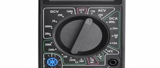
- Using a voltmeter;
- Using an oscilloscope (motor tester).
Since this instruction is intended for the common man who simply cannot have professional equipment in principle, we will diagnose the sensor using a voltmeter.
Method one: reading trouble codes
In order to read the fault codes located in the controller’s memory, it is necessary to either connect special diagnostic equipment to the diagnostic block (located on the left side under the instrument panel console) (too simple - not for us), or close contact “B” to ground, which is so The same can be done by connecting contacts “A” and “B”.
Diagnostic block VAZ 2110
- “A” - contact connected to the vehicle ground;
- “B”—controller signal contact;
- “G” — control of the VAZ fuel pump;
- “M” is a contact for issuing information (serial data).
After these contacts are closed, turn the ignition key to position “III” (do not start the engine), observe the “CHECK” indicator, which should flash the number 12:
- Flash;
- 1-2 second pause;
- Flash;
- Flash;
- Long pause of 2-3 seconds;
- Double repetition of the above cycle.
Reading fault code number “12”
Attention! This code indicates that the self-diagnosis program is running, otherwise this program does not work.
After this, the program displays codes of existing faults in a triple cycle (each code three times), in the absence of these, code “12” continues to be displayed constantly.
Attention! When the diagnosis is completed, these contacts are allowed to be opened only after the ignition is turned off, after ten seconds.
Erasing fault codes from the ECU memory in order to make sure that the fault has been eliminated occurs by turning off the controller's power for at least ten seconds. The power is turned off either by disconnecting the negative terminal from the battery or by removing the controller fuse.
Attention! Operations with power supply to the controller must be carried out strictly with the ignition off!
Method two: checking changes in LP parameters
So, let's get to the “delicious” part:
- We connect the negative probe of the voltmeter to the car body;
- We connect the positive probe to the signal wire of the lambda probe;
- Warm up the engine to operating temperature;
- We warm up the sensor itself by setting the engine speed to 2500 - 3000 rpm for three minutes.
We observe the sensor:
- It must turn on, that is, the voltage must be in the range of 0.8 - 1.0 volts and turn on at a frequency of 8 - 10 times every ten seconds;
- If the voltmeter shows a value of 0.45 volts and it does not change, then the sensor does not work - replace it;
- When the damper is opened sharply, the voltage should jump to about one volt, and when closed sharply, it should drop to almost zero.
What and how can you check the lambda?
To check, you will need a digital voltmeter (preferably an analog voltmeter, since its “sampling” time is much shorter than that of a digital one) and an oscilloscope, if possible, the measurements will be more accurate. Before checking, you should warm up the car since lambda operates correctly at temperatures above 300C°.
First we look for the heating wire:
We start the engine, do not disconnect the lambda connector. We connect the negative probe of the voltmeter (ordinary gauge) to the car body. We “poke” the positive probe on each wire contact and observe the voltmeter reading. When the positive wire of the heater is detected, the voltmeter should show a constant 12 V. Next, using the negative probe of the voltmeter, we try to find the negative wire of the heater. We connect to the remaining contacts of the sensor connector. If a negative contact is detected, the voltmeter will again show 12 V. The remaining wires are signal wires.
How to check the oxygen sensor on a VAZ 2107?
Malfunctions of the oxygen sensor may be “undetected” by the engine ECU, so the “Check Engine” lamp may not light up. It lights up only when the sensor is completely inoperable. If it simply produces incorrect information, the system will not notice the malfunction.
When manually diagnosing a lambda probe, you need to remove the terminal from it and check the voltage on the signal wire coming from the computer. The normal value is 0.45V. A common problem is voltage higher than rated. This can be corrected by connecting an additional resistor to the circuit. Its value is calculated using a variable resistor. It must be connected to the sensor's power circuit, connect the sensor and a voltmeter. Then, with the ignition on, change the resistance of the resistor, observing the voltmeter readings. The required voltage is 0.45-0.46 volts. Then it remains to measure the resistance of the variable resistor and replace it with the corresponding constant resistance.
Now let's look at the error codes associated with lambda.
Error “PO131” indicates a low sensor signal level. It’s easy to understand whether the mixture is really lean or the lambda probe is faulty. With the engine running, you need to spray a little gasoline from a syringe into the intake manifold while the “return” is pinched. If the sensor shows the mixture is too rich, it is working. If the error code indicates a rich mixture, you need to check the sensor differently. You will need to suck air into the manifold. You can organize it by dropping the vacuum brake booster hose. If the sensor responds, it does not need to be replaced.
If, during artificial enrichment and depletion of the mixture, the sensor produces the “native” 0.45 V, it should be replaced.
Important: the VAZ 2107 lambda probe reacts to the oxygen content in the mixture. If air leaks occur in the injection system, the sensor will command the ECU to enrich the mixture, which will lead to an increase in fuel consumption.
Publication date: January 16, 2022. Category: Automotive equipment.
Lambda probe (also called oxygen controller, O2 sensor, DC) is an integral part of the exhaust system of vehicles that meet EURO-4 environmental standards and higher. This miniature device (usually 2 or more lambda probes are installed) monitors the O2 content in vehicle exhaust mixtures, thereby significantly reducing the emission of toxic waste into the atmosphere.
If the DC is not operating correctly or if the lambda probe is disconnected, the functioning of the power unit may be disrupted, causing the engine to go into emergency mode (the Check Engine light will light up on the panel). To prevent this from happening, the car system can be outsmarted by installing a decoy.
The main causes of lambda probe malfunctions and the consequences of its breakdown
Once we have defined the concept and operating features of the oxygen sensor, we can conclude that it plays a key function in the normal operation of the internal combustion engine. So what can cause the lambda probe to break down and fail? There are two aspects to this issue: external factors and internal ones, about which read below.
- Coolant or brake fluid leaking into the sensor housing;
- Caring for the sensor with means that are not intended for such purposes;
- Poor quality fuel with excessive lead content;
- Overheating of the sensor, which also happens when using bad fuel.
After the lambda probe fails your car will begin to show certain signs:
- Significant jerks when moving;
- Excessive fuel consumption;
- Poor performance of the catalyst;
- Floating engine speed;
- Excess toxic waste in exhaust gases.
The seriousness of all of the above should prompt the driver to check the lambda probe almost every 10 thousand km. Its complete replacement is desirable after every 40,000 km.
Mechanical snag of the lambda probe (“screw-in”)
“Vvertysh” is a bushing made of bronze or heat-resistant steel. The inside of such a “spacer” and its cavities are filled with ceramic chips with a special catalytic coating. Due to this, the exhaust gases are burned faster, which, in turn, leads to different indicators of pulses 1 and 2 DC.
Important! Any snag is installed only on a working lambda probe.
A homemade lambda probe decoy, the diagram of which is presented below, is easy to manufacture. To do this you will need to prepare:
The blende is made on a processing lathe. If there is none, then you can contact a specialist by providing him with a drawing.
The resulting part is compatible with most exhaust systems of both domestic and foreign cars.
Installation of the lambda probe blende is carried out as follows:
- Lift the car onto the overpass.
- Disconnect the negative terminal on the battery.
- Unscrew the first (upper) probe (if there are two of them, then remove the one located between the catalyst and the exhaust manifold).
- Screw the lambda probe into the spacer.
- Reinstall the "advanced" sensor.
- Connect the terminal to the battery.
Healthy! Typically, mechanical blending of the second lambda probe is not performed, since this DC is protected by a catalyst and only controls its condition. The most sensitive is the first sensor, which is installed closest to the collector.
After this, the “Check Engine” system error should disappear. If this method does not work, you can use a more expensive deception.
Connection nuances
If the device breaks down, you can install a sensor recommended by the manufacturer or a similar zirconium probe. Here are the basic rules:
- The colors of the sensor wires vary, but the color that supplies the signal to the electronic circuit is always dark.
- “Earth” comes in yellow, white, and gray shades.
- To connect a 4-wire probe in place of a 3-wire probe, connect the ground wires of the heater and the negative signal system to the ground of the car. The heater wire is connected through a relay circuit to the positive pole of the battery.
Connecting a new probe would be better done by a specialist from a car service center.
Electronic snag
Another way to eliminate problems with the DC is to use an electronic decoy of the lambda probe, the diagram of which is presented below. Since the oxygen sensor transmits a signal to the controller, a decoy circuit connected to the wiring from the sensor to the connector will “crude” the system. Thanks to this, in a situation where the lambda probe is faulty, the power unit will continue to operate correctly.
Healthy! The installation locations for such deception may differ depending on the PBX model. For example, it can be mounted in the central tunnel between the seats, in the dashboard or in the engine compartment.
The decoy circuit is a single-chip microprocessor that analyzes the processes in the catalyst, receives data from the first DC, processes it, converts it to the indicators of the second sensor and issues a corresponding signal to the car processor.
To install this type of snag, you will need a lambda probe connection diagram, which looks like this.
As you can see, there are different pinouts of the lambda probe (4 wires, three and two). The colors of the wires may also vary, most often there are products with 4 pins (2 black, white and blue).
To make a deception device, you will need:
- soldering iron with a fine tip and solder;
- rosin;
- non-polar capacitor with a capacity of 1 µF Y5V, +/- 20%;
- resistor (resistance) 1 mOhm, C1-4 imp, 0.25 W;
- knife and insulating tape.
Healthy! Before installation, it is best to place the circuit in a plastic case and fill it with epoxy.
Next, the electronic snag is mounted on the lambda probe with your own hands as follows:
- Disconnect the negative terminal of the battery.
- “Dissect” the wire that goes from the DC itself to the connector.
- Cut the blue wire and connect it back through the resistor.
- Solder a non-polar capacitor between the white and blue wires.
- Insulate connections.
Below is a do-it-yourself diagram of a lambda probe for pinout into 4 wires.
At the final stage, the following should happen.
Such manipulations should not be performed if you do not have the proper experience. Today, stores offer ready-made decoy circuits that even a novice driver can easily install.
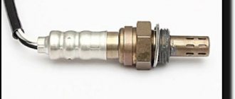
Checking a lambda probe with 4 wires with a tester. Methods for checking LP
So, we come to the question that worries every car enthusiast: how to check the lambda probe sensor at home? To do this, you will need a regular tester (multimeter) or voltmeter.
Lambda probe 4 wires
The first step is to warm up the engine, and then measure the resistance on the heater wires. As a rule, these are two white wires, the polarity between which may not be observed. The normal resistance between them should be from 2 to 10 ohms . If this value is different, then the sensor is faulty.
Lambda probe voltage graph
Let's move on. Now you need to connect the negative wire of the tester to the engine housing. In this case, connect the positive contact to the signal wire of the sensor itself. Typically this will be the black wire. With the engine warm, press the gas pedal and accelerate to 3000 rpm . Hold the pedal in this position for about three minutes. At this time, the lambda probe is warmed up. Now you can check whether the oxygen sensor is turned on.
The voltage between the motor housing and the signal (black wire) of the part should fluctuate between 0.2 and 1 volt . For every 10 seconds , the sensor should turn on about 10 times . In cases where the tester shows 0.4-0.5 volts and does not turn on, we can conclude that the lambda probe is faulty.
You also need to know that when you press the gas pedal sharply, the tester should show a voltage of about 1 volt . When the pedal is suddenly released - zero volts .
That's all for us. We hope that your sensor is fully operational and performs its intended functions. If you have any questions, please leave them in the comments.
How to check the lambda probe and signs of malfunction? Will a Bosch universal fit?
- The car jerks when you drive at low speeds - 1 answer
Reflashing the controller
Some particularly sophisticated car owners decide to reflash the control unit, which blocks the processing of signals from the second oxygen sensor. However, it must be taken into account that any changes to the system operation algorithm can lead to irreversible consequences, since returning the factory settings will be almost impossible and costly. Therefore, it is not recommended to perform such manipulations yourself. The same applies to ready-made firmware that is sold on the Internet.
Healthy! When flashing the lambda probes, they are removed.
If you still want to flash the system, then contact a competent specialist who can disable receiving DC data using specialized equipment.
It is also worth considering that almost any intervention in the operation of systems can lead to not the most pleasant consequences.
What are the consequences after installing decoys?
You need to understand that any deception is installed at the risk of the car owner. If the installation was carried out incorrectly, you may encounter the following problems:
- Due to the fact that the on-board computer cannot regulate fluid injection, engine malfunction may occur.
- If the circuit is not properly soldered, it may damage the wiring.
- In the process of installing the decoy, you can damage the oxygen sensors, after which you will not even know about their malfunction (since you will already have the decoy installed).
- After such interventions (not only during flashing), the on-board computer may fail.
Any inaccuracy will lead to disastrous consequences, so it is better to install a safer ready-made emulator. Unlike deception, it does not “deceive” the control unit, but only ensures its correct operation by converting the DC signal. A microprocessor is also installed inside the emulator (as in a homemade electronic decoy), which is capable of assessing exhaust gases and analyzing the situation.