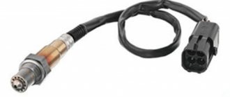
After the destruction or removal of the catalyst or failure of the oxygen sensor (lambda probe), the engine operates in suboptimal mode due to incorrect correction of the air-fuel mixture, and the Check Engine indicator lights up on the instrument panel. Various ways to deceive the electronic control unit can solve this problem.
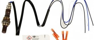
If the oxygen sensor is working properly, a mechanical lambda probe will help; if it fails, you can use an electronic one. Read below to learn how to choose a lambda probe decoy or make it yourself.
How does a lambda probe decoy work?
A lambda probe decoy is a device that ensures that optimal oxygen content in the exhaust gases is transmitted to the ECU if the actual parameters do not correspond to them. This problem is solved by correcting the readings of the existing gas analyzer or its signal. The optimal option is selected depending on the environmental class and car model.
There are two types of deceptions:
- Mechanical (socket bushing or mini-catalyst) . The principle of operation is based on creating a barrier between the oxygen sensor and gases in the exhaust system.
- Electronic (resistor with capacitor or separate controller) . The emulator is placed in a wiring gap or instead of a standard DC. The principle of operation of an electronic lambda probe is to simulate the correct readings of the sensor.
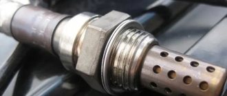
The plug-in sleeve (dummy) allows you to successfully deceive the ECU of old cars that meet an environmental class of at least Euro-3, and the mini-catalyst is suitable even for modern cars with standards up to Euro-6. In both cases, a working DC is required, which is screwed into the blende body. Thus, the working part of the sensor is surrounded by relatively clean gases and transmits normal data to the ECU.
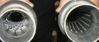
Lambda probe decoy – mini-catalyst (catalyst mesh visible)
Factory customizable lambda probe emulator on a microcontroller
For electronic deception based on a resistor and capacitor, it is not the environmental class that is important, but the operating principle of the ECU. For example, this option does not work on the Audi A4 - the computer will generate an error due to incorrect data. In addition, it is not always possible to select the optimal parameters of electronic components. An electronic fake with a microcontroller independently simulates the operation of an oxygen sensor, even if it is absent and completely inoperable.
There are two types of independent electronic decoys with a microcontroller:
- independent, generating a signal for normal lambda operation;
- corrective readings based on the data of the first sensor.
The first type of emulators is usually used on cars with gas equipment of older generations (up to 3), where when driving on gas it is important to create the appearance of normal operation of the oxygen sensor. The second ones are installed after cutting out the catalyst instead of the second lambda and simulate its normal operation according to the readings of the first sensor.
Diagnostic methods
It is advisable to carry out diagnostics of the sensors every 10,000 km of the vehicle or at the first signs of a probe malfunction, which are described below.
Multimeter
Very often, the reason for the oxygen probe not working is damage to the heater coil or contact with the heater. It is easy to check whether this is true with a multimeter by switching it to the ohmmeter operating mode. Typically, pins 3 and 4 (in a 4-wire sensor) go to the heating element. The resistance value should be within 4.5 - 5.5 Ohms. If the readings exceed this value, the probe requires replacement because the heating element has failed.
To check the signal received by the electronic unit, you need to start the car, press the gas pedal to keep the engine in high-speed mode for some time. We connect the signal wire of the probe (usually black) to the positive probe of the multimeter, and connect the negative probe to ground, switching the device to voltmeter mode (2000 mV). When you hold down the gas pedal and suddenly release it, the readings of the device should be in the range from 1000 mV to 100 mV. If the readings remain unchanged within 400 - 500 mV when manipulating the gas pedal, then the probe is faulty.
Oscilloscope
The quality of testing with an oscilloscope is manifested in the ability to find out the time period of change in the output voltage signal. To check, you need to connect the oscilloscope to the wire that gives a signal to the electronic unit (black). Next, you need to start the engine and wait until it warms up to 70˚C. As the sensor warms up to 400˚C, the device will begin to show a wave-like graph. When the engine is running at about 3000 rpm, the device should show a smooth wave-like graph with a low signal level limit (at least 0.1 V) and a high signal level (no more than 0.8 - 1 V).
If a graph is drawn on the screen at the extreme (upper or lower) points, as well as at a position of about 0.6 V at maximum engine operation, then the λ probe is faulty.
How to make a lambda probe yourself
Making a lambda probe with your own hands: video of making a spacer
If you have the necessary tools, you can make the lambda probe blende yourself. The easiest to manufacture is a mechanical bushing and an electronic simulator with a resistor and capacitor.
To make a pacifier you need:
- metal lathe;
- a small piece of bronze or stainless steel (length about 60–100 mm, thickness about 30–50 mm);
- cutters (cutting, boring and threading) or cutters?, tap and die.
To make an electronic lambda probe you will need:
Making an electronic fake oxygen sensor with your own hands: video
- capacitors 1–5 µF;
- resistors 100 kOhm - 1 mOhm and/or trimmer with this range;
- soldering iron;
- solder and flux;
- insulation;
- box for the case;
- sealant or epoxy.
Turning a screw and making a simple electronic blende, if you have the appropriate skills (lathe/soldering electronics), will take no more than an hour. It will be more difficult with the other two options.
Finding the necessary components to make a mini-catalyst at home will be difficult, and to create an independent signal simulator on a microcontroller, in addition to a microchip, basic electronics and programming skills are required.
Next, we will tell you how to fake a lambda probe after removing the catalyst so that Check Engine errors with codes P0130-P0179 (lambda-related), P0420-P0424 and P0430-P0434 (catalyst errors) do not occur.
It makes sense to deceive the first (or the only one on a car up to Euro-3) lambda probe only when driving an injector with installed 1-3 generation LPG (without feedback)! When driving on gasoline, it is extremely undesirable to distort the readings of the upper oxygen sensor, because the air-fuel mixture is adjusted according to them!
Electronic decoy circuit
The electronic decoy of the lambda probe works on the principle of distorting the real sensor signal to the one that is needed for normal engine operation. There are two system options:
- With resistor and capacitor . A simple circuit that allows you to change the shape of the electrical signal from the DC by soldering in additional elements. The resistor serves to limit voltage and current, and the capacitor serves to eliminate voltage ripple across the load. This type of blende is usually used after cutting out the catalyst to simulate its presence.
- With microcontroller . An electronic lambda probe with its own processor is capable of generating a signal that simulates the readings of a working oxygen sensor. There are dependent emulators tied to the first (upper) DC, and independent ones that generate a signal without external instructions.
The first type is used to deceive the ECU after the catalyst has been removed or failed. The second one can also serve for these purposes, but is more often used as a decoy of the first lambda probe for normal driving with LPG of older generations.
Electronic circuit diagram of the oxygen sensor
The electronic decoy of the lambda probe, the diagram of which is presented above, consists of only two elements and is easy to manufacture, but may require the selection of radio components at nominal value.
Integrating resistor and capacitor into wiring
Electronic lambda probe on a resistor with a capacitor
The resistor and capacitor can be integrated into a car with two oxygen sensors with environmental class Euro-3 and higher. Do-it-yourself electronic deception of a lambda probe is done as follows:
- the resistor is soldered into the gap in the signal wire;
- a non-polar capacitor is connected between the signal wire and ground, after the resistor, on the side of the sensor connector.
The principle of operation of the simulator is simple: the resistance in the signal circuit reduces the current coming from the second oxygen sensor, and the capacitor smoothes out its pulsations. As a result, the injector ECU “thinks” that the catalyst is functioning and the oxygen content in the exhaust is within normal limits.
Do-it-yourself lambda probe decoy diagram
To obtain the correct signal (pulse shape), you need to select the following details:
- non-polar film capacitor from 1 to 5 µF;
- resistor from 100 kOhm to 1 MOhm with power dissipation of 0.25–1 W.
To simplify things, you can first use a trimmer resistor with this range to find the appropriate resistance value. The most common circuit is with a 1 MΩ resistor and a 1 μF capacitor.
You need to connect the snag into the gap in the sensor wiring harness, preferably away from hot exhaust elements. To protect radio components from moisture and dirt, it is better to place them in a housing and fill them with sealant or epoxy resin.
The emulator can be made in the form of an adapter-spacer between the female and male lambda probe connectors, using the appropriate connectors.
Microprocessor board in the lambda probe wiring break
An electronic lambda probe on a microcontroller is needed in two cases:
- substitution of readings from the first (or only) oxygen sensor when driving on 2nd or 3rd generation gas equipment;
- substituting the readings of the second lambda on cars with Euro-3 and higher without a catalyst.
You can assemble an oxygen sensor emulator on a microcontroller with your own hands for HBO using the following set of radio components:
- integrated circuit NE555 (main controller generating pulses);
- capacitors 0.1; 22 and 47 uF;
- resistors to 1; 2.2; 10, 22 and 100 kOhm;
- Light-emitting diode;
- relay.
Do-it-yourself electronic lambda probe - circuit diagram for HBO
The snag described above is connected via a relay to the signal wire section between the oxygen sensor and the ECU. When operating on gas, the relay includes an emulator in the circuit, which generates fake oxygen sensor signals. When switching to gasoline, the oxygen sensor is connected directly to the computer using a relay. In this way, the normal functioning of the lambda on gasoline and the absence of errors on gas are simultaneously achieved.
If you buy a ready-made emulator of the first lambda probe for HBO, it will cost about 500–1000 rubles.
You can also make an electronic decoy of a lambda probe to simulate the readings of the second sensor with your own hands. For this you will need:
- 10 and 100 Ohm resistors (2 pcs.), 1; 6.8; 39 and 300 kOhm;
- capacitors 4.7 and 10 pF;
- amplifiers LM358 (2 pcs.);
- Schottky diode 10BQ040.
The electrical circuit of the specified emulator is shown in the image. The principle of operation of the blende is to change the output readings of the first oxygen sensor and transmit them to the ECU under the guise of readings from the second.
Scheme of a simple electronic emulator of the second lambda probe
The given circuit is universal; it allows you to simulate the operation of both titanium and zirconium oxygen sensors.
A ready-made emulator of the second lambda probe based on a microcontroller will cost from 1 to 5 thousand rubles, depending on the complexity.
Mechanical blende drawing
Drawing of a mechanical lambda probe for many zirconium sensors for Euro-3: click to enlarge
A mechanical lambda probe can be used on a car with a removed catalyst and a working second (lower) oxygen sensor. A dummy screw with a hole works normally on cars of Euro-3 class and below, the sensors of which are not very sensitive. The mechanical blende of the lambda probe, the drawing of which is shown in the illustration, belongs to this type.
For Euro 4 and higher, you need a blende with a miniature catalytic converter inside. It will purify gases directly in the sensor area, thereby simulating the operation of a missing standard catalyst. It is more difficult to make such a lambda probe decoy with your own hands, since it requires a catalytic substance.
Bushing with mini catalyst
To make a mechanical lambda probe with your own hands, you will need a lathe and the ability to work with it, as well as:
- a blank of bronze or heat-resistant stainless steel approximately 100 mm in length and 30–50 mm in diameter;
- cutters (cutting, boring and threading);
- tap and die M18x1.5 (instead of cutters for cutting threads);
- catalytic element.
The main difficulty is the search for the catalytic element. The easiest way is to cut it out from the filler of a broken catalyst, selecting a relatively intact section of it.
Ceramic powder, which is recommended to be used on some Internet resources, is not suitable for these purposes!
Do-it-yourself lambda probe with mini-catalyst: drawing of a spacer: click to enlarge
The oxidation of carbon monoxide and unburned hydrocarbons in the catalyst is ensured not by the ceramic itself, but by the sputtering of noble metals (platinum, rhodium, palladium) applied to it. Therefore, a conventional ceramic filler is useless - it serves only as an insulator, reducing the flow of gases to the sensor, which does not give the desired effect.
You can use the remnants of an already collapsed catalytic converter to create a second lambda probe with your own hands, so don’t rush to hand it over to buyers.
A factory mechanical lambda probe with a mini-catalyst costs 1–2 thousand rubles.
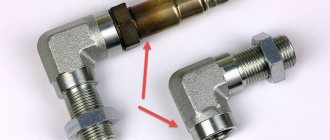
If the space in which the oxygen sensor is located on the exhaust line is very limited, a standard oxygen sensor with a spacer may not fit! In this case, you need to make or buy an L-shaped corner blende.
Screwdriver with a small diameter hole
The lambda probe socket is made in exactly the same way as the mini-catalyst. For this you need:
- lathe;
- a blank made of bronze or heat-resistant stainless steel;
- a set of cutters and/or a tap and die M18x1.5.
Do-it-yourself mechanical snag of a lambda probe: drawing of a screwdriver
The only difference in design is that there is no catalytic filler inside, and the hole in the lower part has a smaller (2–3 mm) diameter. It limits the flow of exhaust gases to the oxygen sensor, thereby providing the desired readings.
Possible consequences
This method of fooling a car computer is a risky endeavor. The following may happen:
- Failure of all sensors without the right to restoration.
- Many different errors can appear in the on-board computer.
- Wiring problems.
- The engine may malfunction because when the computer should give a signal - to supply a rich mixture or, conversely, a lean mixture, but it will not do this, because the snag shows that everything is normal.
How long does the lambda probe snag last?
Mechanical oxygen sensor decoys without catalytic filler are the simplest and most durable, but not very effective. They operate without problems on Euro-3 environmental class engines equipped with low-sensitivity lambda probes. How long a lambda probe of this type lasts depends only on the quality of the material. When using bronze or heat-resistant steel, it can last forever, but sometimes (every 20-30 thousand km) it requires cleaning the hole from carbon deposits.
For newer cars, you need a blende with a mini-catalyst inside, which also has a limited resource. After the catalytic filler is exhausted (occurs after 50-100 thousand km), it ceases to cope with the assigned tasks and turns into a complete analogue of a simple screwdriver. In this case, the simulator must be changed or filled with fresh catalytic material.
Electronic decoys are theoretically not prone to breakdowns and wear, since they do not experience mechanical stress. But the resource of radio components (resistors, capacitors) is limited, over time they degrade and lose their properties. The emulator may fail prematurely if dust or moisture gets into the components due to a leak.
| LZ blende type | Car Compatibility | How to maintain LZ blende | How long does LZ blende last (how often to change) |
| Mechanical (screw-in) | 1999–2004 (EU production), until 2013 (Russian production), cars up to Euro-3 inclusive. | Periodically (every 20–30 thousand km) it may be necessary to clean the hole and cavity of the sensor from carbon deposits. | Theoretically, eternal (just a mechanical adapter, nothing to break). |
| Mechanical (mini-catalyst) | From 2005 (EU) or 2013 (Russia) to present. c., class Euro-3 and higher. | After completing its service life, it requires replacement or replacement of the catalytic filler. | 50–100 thousand km, depending on the quality of the filler. |
| Electronic board) | Independent emulators manufactured before 2005 (EU) or before 2013 (Russia), environmental class Euro-2 or Euro-3 (where it makes sense to install gas equipment of 2 and 3 generations). Emulators that use the readings of the first DC to deceive the second lambda probe - from 2005 (EU) or 2008 (Russia) to present. c., class Euro-3 and higher, but exceptions are possible, the correct selection of denominations is important. | Does not require maintenance if located in a dry, clean place and isolated from moisture and dirt. | Depends on the quality of the electronic components. It should be enough for the entire service life of the car, but it may be necessary to resolder electrolytes and/or resistors if low-quality components are used. |
| Electronic (resistor and capacitor) | Cars from 2005 (EU) or 2008 (Russia), class Euro-3 and higher. | It is worth periodically inspecting the integrity of the elements. | Depends on the quality of radio components and the correct selection of ratings. If the components are selected correctly, do not overheat and do not get wet, it may last for the entire service life of the car. |
Tips and tricks
As you can see, a catalytic converter error can be a real problem for the owner, and a large amount of money is required to replace the catalytic converter on the car.
Of course, you can install a lambda trick, but you should remember that this solution is not always possible to integrate well, especially on “fresh” cars. For this reason, it is advisable to follow certain rules to increase the service life of the catalyst.
We also recommend reading the article about why engine speeds fluctuate when hot. From this article you will learn about the main reasons for floating speed after warming up the internal combustion engine, as well as methods for diagnosing and solving this problem.
First of all, it is important to understand that bad fuel can damage the catalyst. You should only refuel at proven gas stations, and also fill in gasoline of the brand recommended by the car manufacturer itself (for example, you cannot pour cheaper AI-92 gasoline into a car where the use of AI-95 or AI-98 fuel is allowed.)
Secondly, you should not actively pour various fuel additives into the tank, especially from little-known manufacturers. The effect may be questionable, and the damage to the catalyst may be great.
Third, any mechanical impact on the catalyst should be avoided (during car repairs and when operating the car). The fact is that the ceramic honeycomb of the catalyst is very fragile and can crumble even during aggressive off-road driving.
You also need to drive through puddles and snow piles carefully, since in this case the highly heated catalyst quickly cools. Such temperature changes can quickly destroy the fragile honeycomb of the catalyst.
Which lambda decoy is better?
Unambiguously answer the question “Which lambda decoy is better?” impossible. Each device has its own pros and cons, and different compatibility with certain models. Which lambda probe decoy is best installed depends on the purpose of this manipulation and specific conditions:
- mechanical blende operate only in conjunction with a working oxygen sensor;
- To simulate the normal operation of an oxygen sensor on an old gas equipment, only electronic fakes with a microcontroller (pulse generator) are suitable;
- on old cars of a class no higher than Euro-3, it is better to install a screw-in screw - cheap and reliable;
- on more modern cars (Euro-4 and higher) it is better to use mini-catalysts;
- the option with a resistor and capacitor is a cheaper, but less reliable type of blende for new cars;
- An emulator of a second lambda probe on a microcontroller, powered by the first one, is the best option for a car with a failed or removed second oxygen sensor.
Generally speaking, a mini-catalyst is the best option for a working DC, because it highly reliably imitates the operation of a standard converter. A microcontroller is a more complex and expensive option, and therefore is only appropriate when there is no standard sensor at all or it needs to be tricked to drive on gas.
Reflashing the controller
Some particularly sophisticated car owners decide to reflash the control unit, which blocks the processing of signals from the second oxygen sensor. However, it must be taken into account that any changes to the system operation algorithm can lead to irreversible consequences, since returning the factory settings will be almost impossible and costly. Therefore, it is not recommended to perform such manipulations yourself. The same applies to ready-made firmware that is sold on the Internet.
Healthy! When flashing the lambda probes, they are removed.
If you still want to flash the system, then contact a competent specialist who can disable receiving DC data using specialized equipment.
It is also worth considering that almost any intervention in the operation of systems can lead to not the most pleasant consequences.
Buying a ready-made emulator
As mentioned earlier, if you can’t make the decoy yourself, buy a ready-made one. Their variety is quite large, the range and prices in Moscow are as follows:
- An electronic version or catalyst emulator will cost 1,500 rubles, while an additional 500 rubles will have to be paid for the installation of the part in question.
- A corner blende costs around 1,400 rubles.
- The second sensor decoy, equipped with a metal minicatalyst, costs about 1,150 rubles and is suitable for cars with Euro-4 standards.
- A classic mechanical bushing from FortLuft will cost 500 rubles. This part is not equipped with a minicatalyst and is suitable for cars produced before 2001.
Do-it-yourself electronic catalyst blende and emulator circuit
A real electronic emulator is a microprocessor device consisting of a single-chip microcircuit. The principle of its operation is based on the formation of an output signal, which in shape corresponds to the information in the working neutralizer. This option is difficult to do on your own, so you should immediately consider a simpler method. To implement it you need to prepare:
- Electric soldering iron.
- Solder and rosin.
- Knife and side cutters.
- Resistance 200 Kom, power 0.25 W.
- The capacitor is non-polar with a capacity of 4.7 microfarads.
Catalyst care
The ecology of our planet does not respond well to such tricks, so it is better to purchase and install new parts if they fail. Think of the emulator as a temporary solution and try to avoid catalytic converter failure.
- give preference only to high-quality fuel;
- avoid deep puddles so that the heated catalyst is not subjected to sudden cooling;
- refuse questionable fuel additives from unknown manufacturers;
- undergo regular maintenance;
- Avoid mechanical damage to the housing.