Compact car Volkswagen Golf 6
generation was produced with hatchback, station wagon and convertible bodies in 2008, 2009, 2010, 2011, 2012 and 2013. Our material will provide a description of the fuse and relay blocks of the Volkswagen Golf 6 with diagrams and photo examples. We will separately highlight the fuse responsible for the cigarette lighter. And in conclusion, we will offer for download a complete repair and maintenance manual for the Golf 6.
If the model generation is not suitable, then read the description for and accordingly.
Location and layout
Let's look at the diagrams and location of the power supply in Volkswagen Golf cars of the second, third, fourth, fifth and sixth generations. In all cases, the device is located on the driver's side under the instrument panel. The only difference is that in models of the second and third generations the power supply is located on a shelf under the steering wheel. And in models of the fourth, fifth and sixth generations - directly in the dashboard on the side where the driver's door comes into contact with the panel.
Volkswagen Golf 2
The location of the block in this vehicle model is on the left side in the area of the driver’s seat under the dashboard. We invite you to familiarize yourself with the diagram and decoding of the power supply components.
Fuse box FV Golf second generation
| Number | Purpose |
| 1, 2 | These power supply components are responsible for the functionality of the left and right low beam headlights. |
| 3 | This fuse ensures the operation of the instrument panel lighting and lamps that illuminate the license plate of the car. |
| 4 | This component ensures the functioning of the glove compartment lighting bulbs. |
| 5 | Responsible for the operation of the windshield wiper and washer motor. |
| 6 | Guarantees the operation of the interior heater fan. |
| 7 | Responsible for the operation of the right rear headlight and brake lights. |
| 8 | Provides heated rear window. |
| 9 | Fog lights. |
| 10,11 | Responsible for the performance of high beam lights. |
| 12 | Steering horn. |
| 13 | Provides functionality for rear position lights. |
| 14 | Determines the functionality of the fuel shut-off valve. |
| 15 | If this element fails, the operation of the instrument panel may be disrupted. |
| 16 | Guarantees the functionality of the alarm system. |
| 18 | If this element fails, the operation of the radiator fan and air conditioner is impossible. |
| 19 | Responsible for brake lights. |
| 20 | Car interior lighting. |
| 21 | Guarantees the operation of the multimedia system or radio, as well as the cigarette lighter. |
Fuses numbered 17 and 22 are spare.
Volkswagen Golf 3
The power supply circuit on this vehicle model is similar to the power supply installed in the second version of the car, but there are some differences. Therefore, we will consider the circuits and purpose of power supply elements separately. Location: on the dashboard on the left side, on the shelf under the steering wheel.
Diagram of the power supply installed in Volkswagen of the third version
| Number | Purpose |
| 1, 2 | Low beam lamps, left and right. |
| 3 | Car license plate lights. |
| 4,5 | Responsible for the operation of the windshield and rear window washer and wiper motors. |
| 6 | Guarantees the functionality of the heating element of the heating system. |
| 7,8 | If this component fails, the vehicle's rear and front side lamps will not work. |
| 9 | Rear window heating device. |
| 10 | Guarantees the functionality of the fog lights. |
| 11,12 | Responsible for the functionality of the left and right high beam lamps. |
| 13 | Steering horn. |
| 14 | If this component breaks down, the reversing lamps will stop working, as well as the washer nozzle heating device. |
| 15 | Responsible for the functionality of the gasoline shut-off valve, as well as the speedometer drive sensor. |
| 16 | If this element breaks down, malfunctions or inaccuracies in the operation of the instrument panel may occur. |
| 17 | Functioning of turn signal lamps and hazard warning lights. |
| 18 | If this fuse is blown, the car will not start because this component ensures the operation of the fuel pump. |
| 19 | Air conditioning and radiator cooling fan. |
| 20 | Lamp lights that turn on when you press the brake pedal. |
| 21 | Guarantees the functionality of car interior lighting bulbs, electronic clocks, and luggage compartment lighting. |
| 22 | Responsible for the operation of the multimedia system or car radio, as well as the cigarette lighter. |
Volkswagen Golf 4
Below is a diagram and purpose of power supply devices for the fourth version of PV. The block itself is located on the left side of the dashboard, near the driver's seat. To access it and see it in person, you need to remove the cover using a slotted screwdriver.
Volkswagen Golf 5, 6
For models of the fifth and sixth versions, the power supply circuit will be the same. The location of the power supply is on the left side of the instrument panel, in the area where the driver's door comes into contact with the dashboard. Below is a diagram and description of all components.
Fuse and relay box in the cabin
The interior fuse box in the Volkswagen Golf III is located near the pedal assembly and is covered with a decorative cover.
Location of the unit in the cabin
The schematic diagram and explanation are given below.
Appearance
Fuse and relay layout
Relay
Diagram number Switched circuit
| 1 | Air conditioner |
| 2 | Rear window wiper/washer |
| 3 | ECU |
| 4 | Main ignition circuits |
| 5 | — |
| 6 | Turn signal switch |
| 7 | headlight washer |
| 8 | Windshield wiper/washer intermittent relay |
| 9 | Seat belt indicator 1995 |
| 10 | PTF |
| 11 | Sound signal |
| 12 | Fuel pump |
| 13 | Intake manifold heater |
| 14 | — |
| 15 | ABC pump |
| 16 | Reversing lights (Ecomatic) |
| 17 | High beam (Ecomatic) |
| 18 | Low beam (Ecomatic) |
| 19 | Fuse (30A - air conditioning, Climatronic 2.0/2.8 (1993) |
| 20 | Start inhibit switch |
| 21 | Oxygen sensor |
| 22 | Seat belt indicator (1995) |
| 23 | Vacuum pump (Ecomatic) |
| 24 | Thermal fuse - Power windows |
Circuit breakers
Number on the diagram Rating Protected circuit/consumer
| F1 | 10 | Low beam: left side |
| F2 | 10 | Low beam: right side |
| F3 | 10 | License plate lamps |
| F4 | 15 | Tailgate glass cleaner and washer |
| F5 | 15 | Cleaners, headlight washers |
| F6 | 20 | Heater fan |
| F7 | 10 | Front and rear dimensions - right |
| F8 | 10 | Front and rear dimensions - left |
| F9 | 20 | Rear window defroster |
| F10 | 15 | PTF |
| F11 | 10 | High beam: left side |
| F12 | 10 | High beam: right side |
| F13 | 10 | Sound signals |
| F14 | 10 | Reversing lights, washer nozzle heaters, central locking, electric door mirrors, heated seats, cruise control, electric windows |
| F15 | 10 | Speedometer, intake manifold heater |
| F16 | 15 | Instrument cluster lights, ABS indicator, SRS indicator, sunroof, Thermotronic heating system |
| F17 | 10 | Hazard warning lamps, direction indicators |
| F18 | 20 | Fuel pump, heated oxygen sensor |
| F19 | 30 | Radiator fan, air conditioning relay |
| F20 | 10 | Brake lights |
| F21 | 15 | Interior, trunk, central locking, sunroof lamps |
| F22 | 10 | Radio, cigarette lighter |
Actions in emergency situations Volkswagen Golf 7. Volkswagen Golf 7 fuses
Due to the constant improvement of the design of the car and its individual systems, as well as the fact that the installation of many fuses, including in the joint power circuits of several different consumers, can depend in a complex way on the presence or absence of certain additional equipment, it is necessary to comprehensively indicate All installation locations and ratings of individual fuses are not possible at the time of publication of this manual. The location of the fuses can be obtained from a Volkswagen workshop. One fuse can protect the circuits of several electrical consumers. And, vice versa: one consumer may have several fuses. Replace fuses only after eliminating the cause of their blown. If the new fuse quickly blows again, have the relevant electrical equipment checked by a workshop.
WARNING The vehicle's electrical system uses high voltage, which can cause electric shocks, severe burns and death! — Do not touch the ignition system wires under any circumstances. — Avoid short circuits in electrical equipment. Using improper fuses, repaired blown fuses, or shorting electrical circuits without fuses can cause fire and serious injury. — Never install fuses with a higher current rating than required. Replace blown fuses only with fuses of the same rating (color and markings must be identical) and size. — Do not use repaired fuses (so-called bugs)!
— It is prohibited to replace fuses with pieces of wire, paper clips and other improvised means!
Note To avoid damage to the vehicle's electrical equipment, before replacing the fuse, turn off the ignition, lights and all electrical consumers and remove the key from the ignition switch. — Using high amperage fuses may cause damage elsewhere in the electrical circuit.
— Protect exposed fuse boxes from dirt and moisture. Dirt and moisture in the fuse box can cause damage to electrical equipment.
Fuses in the vehicle Replace blown fuses only with fuses of the same rating (color and markings must be identical) and size. — Standard blade fuses (ATO®). — Small flat fuses (MINI®). — JCASE® fuses.
| Color | Current strength, A | |
| (ATO®/MINI®) | (JCASE®) | |
| Black | 1 | — |
| Beige | 5 | — |
| Brown | 7,5 | — |
| Red | 10 | 50 |
| Blue | 15 | 20 |
| Yellow | 20 | 60 |
| White or transparent | 25 | — |
| Green | 30 | 40 |
| Orange | 40 | — |
| Pink | 30 | 30 |
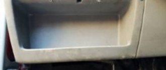
Front fuse box Opening the front fuse box Front fuse box cover: left, next to the steering wheel Open the driver's side storage compartment and pull firmly on the left side in the direction of the arrow. This may require some effort.
To install, insert the storage compartment into the opening of the front panel and press until it is clearly secured.
Fuse table in the front panel fuse box The table shows the locations of fuses that may be of interest to the customer.
The left column lists the fuse socket, then the fuse type, the amperage rating, and the last column shows the consumer(s) that receives supply voltage through that fuse.
Location of fuses in the front panel
| Nest | Fuse type | Current in amperes | Consumers |
| F4 | MINI® | 7,5 | Control panel of the information and command system (Infotainment) |
| F7 | MINI® | 10 | Air conditioning or heater control panel, heated rear window relay, automatic transmission selector lever |
| F8 | MINI® | 10 | Light switch, rain sensor, electromechanical parking brake |
| F10 | MINI® | 10 | Display |
| F12 | ATO® | 20 | Infotainment system components |
| F14 | ATO® | 30 | Fan regulator |
| F16 | MINI® | 7,5 | Telephone |
| F20 | MINI® | 15 | Seat position adjustment |
| F23 | JCASE® | 40 | Headlights and Exterior Lighting |
| F24 | ATO® | 30 | Panoramic tilt/slide sunroof with electric drive |
| F26 | ATO® | 30 | Heated seats |
| F28 | ATO® | 20 | Trailer control unit (left) |
| F31 | JCASE® | 40 | Headlights and Exterior Lighting |
| F38 | ATO® | 20 | Trailer control unit (right) |
| F40 | ATO® | 20 | Cigarette lighter, sockets |
| F42 | ATO® | 40 | Windshield washer, headlight washer |
| F43 | JCASE® | 30 | Interior lighting |
| F44 | ATO® | 15 | Trailer control unit |
| F47 | ATO® | 15 | Rear window wiper |
| F53 | ATO® | 30 | Heated rear window |
Removal and replacement
The replacement process is identical for all versions of the FV. To replace, you will need a screwdriver or wrenches, depending on whether the power supply is attached to the body with bolts or self-tapping screws. Decide which tool you need, and you can start removing.
- Using a screwdriver, disconnect the dashboard trim behind which the power supply is installed in your car.
- Unscrew the screws securing the power supply to the car body.
- Pull out the device: it will hang on the wires.
- Take the new power supply unit and, one by one, disconnecting it from the old device, insert all the necessary wires into the connectors of the new power supply unit.
- Install the new power supply in place by tightening the fastening screws and closing the instrument panel trim.
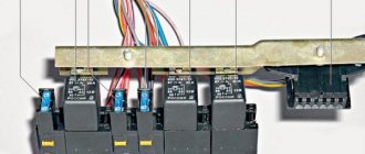
Pinout of the PP module and Golf 3 relay
On the cover of the interior fuse and relay module there is a diagram of the designations of the protected elements. A special connector contains a tool for replacing fusible elements and spare fuses.
Deciphering the interior fuse module diagram for Volkswagen Golf 3
Protected electrical circuit or device Rating, АColor No.
| A/C compressor, relay | 1 | ||
| Rear view wiper, rear view washer, relay | 2 | ||
| ECU, Main Engine Control Unit, Main Relay | 3 | ||
| Electronic ignition system, relay | 4 | ||
| Reserve connector | 5 | ||
| Front and rear turn signal light breaker, relay | 6 | ||
| Headlamp washer motor controller, relay | 7 | ||
| Windshield wiper mode controller, windshield washer mode controller, relay | 8 | ||
| Front passenger seat belt buzzer, used on vehicles manufactured after 1995, relay | 9 | ||
| Front fog lights, relay | 10 | ||
| Two-tone horn, relay | 11 | ||
| +12V power supply for fuel pump, relay | 12 | ||
| Air heating in the intake manifold, relay | 13 | ||
| Reserve connector, relay | 14 | ||
| ABS hydraulic unit motor, relay | 15 | ||
| Reverse gear light, relay | 16 | ||
| Head optics, low beam bulbs, relay | 17 | ||
| Head optics, high beam bulbs, relays | 18 | ||
| Power fuse for the air conditioning compressor on cars with climate control, after 1993, with 2.0 l and 2.8 l engines | 19 | ||
| Unauthorized engine start attempt interrupter, relay | 20 | ||
| Exhaust gas oxygen sensor, heating coil relay | 21 | ||
| Front passenger seat belt buzzer, used on cars produced before 1995, relay | 22 | ||
| Vacuum brake booster, relay | 23 | ||
| Thermal fuse for power window motor | 24 | ||
| Right headlight, low beam bulb, electric motor for headlight height adjustment | 10 | Red | F1 |
| Left headlight, low beam bulb | 10 | Red | F2 |
| Rear license plate lamps | 10 | Red | F3 |
| Rear window wiper, rear view window washer motor | 15 | Blue | F4 |
| Windshield wipers, windshield washer motor, headlight washer motor | 15 | Blue | F5 |
| Electric motor of the main interior heater | 20 | Yellow | F6 |
| Left side, parking light bulbs, front and rear | 10 | Red | F7 |
| Right side, parking light bulbs, front and rear | 10 | Red | F8 |
| Heated rear view glass | 20 | Yellow | F9 |
| Front fog light bulbs | 15 | Blue | F10 |
| Right headlight, high beam bulb | 10 | Red | F11 |
| Left headlight, high beam bulb | 10 | Red | F12 |
| Two-tone buzzer in the cabin | 10 | Red | F13 |
| Complex fuse: | 10 | Red | F14 |
| side window drive motor; | |||
| reverse gear light bulbs; | |||
| cruise control system; | |||
| heated windshield washer jets; | |||
| heated front car seats; | |||
| central locking system; | |||
| adjusting the exterior rearview mirrors | |||
| Additional heating of air in the intake manifold, vehicle speed measuring device | 10 | Red | F15 |
| Thermotronic additional heating system, electric sunroof, AirBag system indicator, ABS system indicator, main instrument panel lighting | 15 | Blue | F16 |
| Hazard warning button, front and rear turn signal lights | 10 | Red | F17 |
| +12V oxygen sensor power supply, fuel pump power supply | 20 | Yellow | F18 |
| Engine cooling radiator fan motor, air conditioning compressor, relay | 30 | Green | F19 |
| Brake light bulbs in rear lights | 10 | Red | F20 |
| Central locking, power sunroof drive, interior lighting, luggage compartment lighting | 15 | Blue | F21 |
| Car radio, active radio antenna, cigarette lighter socket | 10 | Red | F22 |
Block location
The 4th generation Volkwagen Golf has two PCB modules:
- Engine block - located on the battery cover under the hood. To access the fuses, you need to release the two side latches and lift the cover.
- Cabin module - located on the driver's side on the side of the dashboard. To access the unit, you must open the door and remove the cover.
The fuse description is printed on the cover of the passenger compartment module and replacement pliers are attached.
In addition to the two main blocks, several power fuses are located in separate places:
- fuse for turns and emergency lights - built into the hazard warning light button;
- The fuse for the air supply motor to the manifold is on the engine panel.
Pinout of the PP module and Golf 3 relay
On the cover of the interior fuse and relay module there is a diagram of the designations of the protected elements. A special connector contains a tool for replacing fusible elements and spare fuses.
Deciphering the interior fuse module diagram for Volkswagen Golf 3
Protected electrical circuit or deviceRating, АColor No.
| A/C compressor, relay | 1 | ||
| Rear view wiper, rear view washer, relay | 2 | ||
| ECU, Main Engine Control Unit, Main Relay | 3 | ||
| Electronic ignition system, relay | 4 | ||
| Reserve connector | 5 | ||
| Front and rear turn signal light breaker, relay | 6 | ||
| Headlamp washer motor controller, relay | 7 | ||
| Windshield wiper mode controller, windshield washer mode controller, relay | 8 | ||
| Front passenger seat belt buzzer, used on vehicles manufactured after 1995, relay | 9 | ||
| Front fog lights, relay | 10 | ||
| Two-tone horn, relay | 11 | ||
| +12V power supply for fuel pump, relay | 12 | ||
| Air heating in the intake manifold, relay | 13 | ||
| Reserve connector, relay | 14 | ||
| ABS hydraulic unit motor, relay | 15 | ||
| Reverse gear light, relay | 16 | ||
| Head optics, low beam bulbs, relay | 17 | ||
| Head optics, high beam bulbs, relays | 18 | ||
| Power fuse for the air conditioning compressor on cars with climate control, after 1993, with 2.0 l and 2.8 l engines | 19 | ||
| Unauthorized engine start attempt interrupter, relay | 20 | ||
| Exhaust gas oxygen sensor, heating coil relay | 21 | ||
| Front passenger seat belt buzzer, used on cars produced before 1995, relay | 22 | ||
| Vacuum brake booster, relay | 23 | ||
| Thermal fuse for power window motor | 24 | ||
| Right headlight, low beam bulb, electric motor for headlight height adjustment | 10 | Red | F1 |
| Left headlight, low beam bulb | 10 | Red | F2 |
| Rear license plate lamps | 10 | Red | F3 |
| Rear window wiper, rear view window washer motor | 15 | Blue | F4 |
| Windshield wipers, windshield washer motor, headlight washer motor | 15 | Blue | F5 |
| Electric motor of the main interior heater | 20 | Yellow | F6 |
| Left side, parking light bulbs, front and rear | 10 | Red | F7 |
| Right side, parking light bulbs, front and rear | 10 | Red | F8 |
| Heated rear view glass | 20 | Yellow | F9 |
| Front fog light bulbs | 15 | Blue | F10 |
| Right headlight, high beam bulb | 10 | Red | F11 |
| Left headlight, high beam bulb | 10 | Red | F12 |
| Two-tone buzzer in the cabin | 10 | Red | F13 |
| Complex fuse: | 10 | Red | F14 |
| side window drive motor; | |||
| reverse gear light bulbs; | |||
| cruise control system; | |||
| heated windshield washer jets; | |||
| heated front car seats; | |||
| central locking system; | |||
| adjusting the exterior rearview mirrors | |||
| Additional heating of air in the intake manifold, vehicle speed measuring device | 10 | Red | F15 |
| Thermotronic additional heating system, electric sunroof, AirBag system indicator, ABS system indicator, main instrument panel lighting | 15 | Blue | F16 |
| Hazard warning button, front and rear turn signal lights | 10 | Red | F17 |
| +12V oxygen sensor power supply, fuel pump power supply | 20 | Yellow | F18 |
| Engine cooling radiator fan motor, air conditioning compressor, relay | 30 | Green | F19 |
| Brake light bulbs in rear lights | 10 | Red | F20 |
| Central locking, power sunroof drive, interior lighting, luggage compartment lighting | 15 | Blue | F21 |
| Car radio, active radio antenna, cigarette lighter socket | 10 | Red | F22 |
Engine compartment PP
The PP motor block contains several high-rated fuses that protect loaded electrical circuits and elements.
Decoding the motor fuse module.
| Electrical circuit or device | Denomination, A | Color | № |
| Motor for pumping air into the intake manifold | 50 | 131 | |
| ECU, Engine control unit | 50 | 132 | |
| Radiator fan for engine coolant circulation system | 40/50 | 133 | |
| +12V power supply to the general on-board electrical network | 110 | 134 | |
| +12V output from generator | 110/150 | 138 | |
| AB system | 30 | Green | 162 |
| AB system | 30 | Green | 163 |
| Additional radiator fan for engine coolant circulation system | 30 | Green | 164 |
Additional fusible elements
In some versions of Volkswagen Golf 3rd generation vehicles, additional fuses may be used. The following additional elements are used in the interior fuse and relay module:
- rated 30A - power supply to the ABS system relay;
- rated 30A - power supply to the relay of the hydroelectric unit of the ABS system;
- rated 10A - air conditioning compressor for cars without climate control;
- rated 30A - interior ventilation motor with the ClimaTronic system;
- with a nominal value of 5A - controller of the ClimaTronic system;
- rated 5A - +12A power supply to the on-board network of a towed trailer.
For a diesel internal combustion engine, an additional PP for the engine warm-up system is used, with a rated current of 60 A. It is located separately, on the engine panel under the hood.
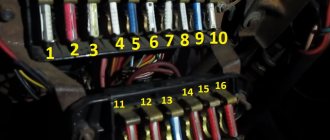
Scheme
To carry out repairs effectively, it is extremely important to know the location and rating of all fuses. You can get this information from the block cover or from the diagrams presented below.
Fuse box Golf 2-3:
Golf 4 fuse box:
Fuse box Golf 5-6:
In general, you can repair the fuse box and replace its individual elements with your own hands without much difficulty. However, for effective repairs, it is very important to use the information presented above.
Relay and fuse layout diagram for Volkswagen Golf 3, Vento (1H)
The information applies to cars: Volkswagen Golf 3 / Volkswagen Golf 3 (1H1, 1H5) 1992 - 1998 Volkswagen Vento / Volkswagen Vento (1H2) 1992 - 1998
Layout of fuses and relays in the PDU Golf 3, Vento and their purpose.
Layout of fuses and relays in the PDU:
01 - 10A - Low beam of the left headlight 02 - 10A - Low beam of the right headlight 03 - 10A - License plate lamps 04 - 15A - Windshield wiper and washer of the rear window 05 - 15A - Wiper and washer of the windshield 06 - 20A - Heater heater 07 - 10A - Right side lights and tail light 08 - 10A - Left side lights and tail light 09 - 20A - Heated rear window 10 - 15A - Fog lights 11 - 10A - Left high beam 12 - 10A - Right high beam 13 - 10A — Bibikalka 14 — 10A — Reversing lights, heated washer nozzles 15 — 10A — Fuel cut-off valve, speedometer drive sensor 16 — 15A — Dashboard 17 — 10A — Direction indicators and emergency lights 18 — 20A — Fuel pump and heated lambda probe 19 - 20A - Radiator and air conditioning fan 20 - 10A - Brake lights 21 - 15A - Interior lighting, electronic clock, MFA, trunk light 22 - 10A - Radio, cigarette lighter
From myself: It seems to me that the fuse for the fastener is combined with the interior lighting and the MFA.
Number in the PDU - Number on the body - Purpose
01 - 13 - Air conditioning compressor relay 02 - 72 - rear wiper and washer relay 03 - 30, 32 - Injection and ignition system relay 04 - 18 - load relief relay, contact X of the ignition switch 05 - not used 06 - 21 and 22 - Relay breakers for turn signals and emergency lights, as well as trailer (No. 22) 07 - 33 - Headlight washer motor relay 08 - 19 and 99 - Relay for wipers and windshield washer 09 - 4 and 29 - Seat belt warning relay 10 - 15 - Jumper wire for PTF 11 - 53 - Sound signal relay (for a single-tone signal - jumper) 12 - 67, 80, 167 - Fuel pump or pre-heater relay (diesel) 13 - 53 - Pre-heating relay (22) or starter interlock relay 14 - 79 — ABS relay 15 — 79 — ABS hydraulic pump relay 16 — 79 — ABS relay 17 — ABS valve and pump fuses 18 — Electric seat and air conditioning fuses 19 — Not used 20 — Starter and reverse light relay 21 — Lambda heating coil relay probe 22 - Not used 23 - Not used 24 - Not used
Diagram and pinout of the rear side of the relay and fuse box
If you have not found information on your car, look at the cars built on the platform of your car. Most likely, the information on repair and maintenance will be suitable for your car.
Volkswagen golf 3 fuses and relays
1 Air conditioning relay 2 Rear window wiper/washer relay 3 Electronic engine control unit relay 4 Main ignition circuit relay 5 - 6 Turn signal switch relay 7 Headlight washer control unit 8 Windshield wiper/washer intermittent operation relay 9 Seat belt indicator relay safety 1995 10 Fog lamp relay 11 Horn relay 12Pro Volkswagen: Volkswagen Golf | Autopedia wiki Fuel pump relay 13 Intake manifold heater relay 14 - 15 ABS pump relay 16 Reversing light relay (Ecomatic) 17 High beam headlight relay (Ecomatic) 18 Low beam headlight relay (Ecomatic) 19 Fuse (30A - air conditioning, Climatronic 2, 0/2.8 (1993) 20 Start inhibit switch relay 21 Oxygen sensor relay 22 Seat belt indicator relay (1995) 23 Vacuum pump relay (Ecomatic) 24 Thermal fuse (20A) – Power windows F1 (10A) Left headlight - low light, electric motors for headlight range control F2 (10A) Low beam - right headlight F3 (10A) License plate lamps F4 (15A) Rear door glass cleaner and washer F5 (15A) Cleaners, washers, headlight washers F6 (20A) Heater fan F7 ( 10A) Front and rear lights - right F8 (10A) Front and rear lights - left F9 (20A) Rear window heater F10 (15A) Fog lights F11 (10A) High beam - left headlight F12 (10A) High beam - right headlight F13 (10A) Sound signals F14 (10A) Reversing lights, washer nozzle heaters, central locking, electric door mirror, seat heater, cruise control system, electric windows F15 (10A) Speedometer, intake manifold heater F16 (15A) Backlight instrument cluster, ABS indicator, SRS indicator, sunroof, Thermotronic heating system F17 (10A) Hazard warning lights, turn signals F18 (20A) Fuel pump, heated oxygen sensor F19 (30A) Radiator fan, air conditioning relay F20 (10A) Brake lights F21 (15A) Interior light dumps, trunk light, central locking, sunroof F22 (10A) Radio, cigarette lighter fuse
Fuse box diagram
Dashboard
Assignment of fuses on the dashboard
| No. | ampere | Function/component |
| 1 | 10 | T16 – Diagnostic connection (T16 / 1) J623 – Engine control unit J757 – Engine component supply relay (167) (from May 2005) J538 – Fuel pump control unit (from May 2005) J485 – Relay for auxiliary heater operation (from 2006) ) N79 – Heating element for crankcase ventilation (from 2006) G70 – Air flow meter (from 2006) J431 – Headlight leveling control unit (from 2006) |
| 2 | 5 | J104 – ABS control unit E132 – Traction control switch E256 – TCS and ESP button E492 – Tire pressure display button F – Brake light switch (low level; from November 2005) |
| 2 | 10 | J623 – Engine control unit (from 2006) V49 – High beam motor (from 2006) V48 – High beam motor (from 2006) E102 – Headlight range control (from 2006) J538 – Control unit fuel pump (from 2006) J345 – Trailer detector control unit (from 2006) J587 – Selector lever sensor control unit (from 2006) J533 – Data bus diagnostic interface (from 2006) J285 – Control unit in the instrument panel insert (from 2006) J500 – Power steering control unit (from 2006) J104 – ABS with EDL control unit (from 2006) E132 – Traction control switch (from 2006) E256 – Button TCS and ESP (since 2006) G476 – Brake pedal position sensor (since 2006) E1 – Light switch (since 2006) F47 – Brake pedal switch (since November 2005) |
| 3 | 10 | J500 – Power steering control unit (before May 2005) |
| 3 | 5 | J234 – Airbag control unit (from May 2005) |
| 4 | 5 | E16 – Heating/heat output switch G65 – High pressure sensor J131 – Heated driver's seat control unit J132 – Heated front passenger seat control unit J255 – Climatronic control unit K216 – Stability program indicator lamp 2 (from May 2005) M17 – Lamp reverse (since May 2005) E422 – Tire pressure monitor display button (since May 2005) G266 – Oil level and oil temperature sensor (high; since May 2005) J530 – Garage door control unit (since May 2005) May 2006) G128 – Seat occupancy sensor, front passenger side (from May 2006) Y7 – Automatic anti-glare interior mirror (from May 2006) Z20 – Left washer jet heating element (from May 2006) Z21 – Right heating element washer jets (since May 2006) |
| 4 | 10 | G266 – Oil level and oil temperature sensor (high; from November 2005) M17 – Reversing light (high; from November 2005) J255 – Climatronic control unit (high; from November 2005) G65 – High pressure sensor (high; since November 2005) E16 – Heater and heater power switch (high; since November 2005) J530 – Garage door control unit (high; since November 2005) N253 – Battery insulation igniter (high ; from November 2005) Y7 – Automatic anti-dazzle interior mirror (high; from November 2005) E422 – Tire pressure monitoring indicator button (high; from November 2005) K216 – Indicator lamp 2 stabilization programs (high; from November 2005) Z20 – Left washer heating element (high; since November 2005) Z21 – Right washer heating element (high; since November 2005) L71 – Traction control switch illumination (high; since November 2005) J301 – Air conditioning control unit (high; since May 2007) |
| 5 | 5 | F47 – Cruise control brake pedal system (up to May 2005) G476 – Clutch position sensor J431 – Headlight range control unit (from May 2005) J500 – Power steering control unit (from May 2005) J745 – Headlight leveling and headlight leveling right headlight assembly (high; December 2006) |
| 5 | 10 | J745 – Turning light and main beam unit, on the right headlight (low; from May 2006), (high; from May 2007) |
| 6 | 5 | J285 – Control unit in instrument panel insert (up to May 2006) J538 – Fuel pump control unit (up to May 2006) J533 – Data bus diagnostic interface (up to May 2006) F125 – Multifunction switch (up to May 2006) J587 – Selector lever sensor control unit (before May 2006) F189 – Tiptronic switch (before May 2006) J745 – Turning light and headlight control unit, left of headlight (high; December 2006) |
| 6 | 10 | J745 – Turning light and main beam unit, on the left headlight (low; from May 2006), (high; from May 2007) |
| 7 | 5 | J431 – Headlight leveling control unit (until May 2005) Y7 – Automatic anti-dazzle interior mirror (since May 2005) Not assigned (since May 2006) |
| 8 | 5 | Y7 – Automatic anti-glare interior mirror (until May 2005) |
| 8 | 10 | J345 - Trailer detector control unit (from May 2005) Not assigned (from May 2006) |
| 9 | 5 | Not assigned (as of May 2005) J503 - Control unit with display for radio navigation system (commercial navigation system unit only) (as of May 2005) Not assigned (as of May 2006) |
| 10 | 5 | J412 – Mobile phone electronics control unit (up to May 2005) J530 – Garage door control unit (from May 2005) J706 – Seat recognition control unit (from May 2005) Not assigned (from May 2006) |
| 11 | 5 | J345 - Trailer detector control unit (before May 2005) Not assigned (from May 2005) |
| 11 | 10 | J745 – Turning and high beam lighting unit, on the right headlight (from May 2007) |
| 12 | 10 | J386 – Driver's door control unit J 387 – Front passenger's door control unit |
| 13 | 10 | E1 – light switch T16 – diagnostic connection (T16 / 16) F47 – brake pedal switch (since May 2005) G397 – rain and light detection sensor (since 2006) G197 – magnetic field sensor for compass (since 2006) |
| 14 | 5 | F – brake light switch (low; from May 2005) J217 – Automatic transmission control unit |
| 14 | 10 | J587 – Selector lever sensor control unit (from 2006) R149 – Remote control receiver for auxiliary heater (from 2006) J301 – Air conditioning control unit (from 2006) J255 – Climatronic control unit (from 2006) E16 – Heater / heating output Switch (since 2006) J446 – Parking aid control unit (since 2006) J104 – ABS with EDL control unit (since 2006) E94 – Driver seat heating control (since 2006) E95 – Regulator heated front passenger seat (from May 2006) J217 – Automatic transmission control unit (from November 2005) |
| 15 | 7,5 | J519 – On-board power supply control unit (interior lighting) |
| 16 | 10 | E16 – Heater/heat output switch J301 – Air conditioning control unit J255 – Climatronic control unit R149 – Remote control receiver for auxiliary coolant heater Not assigned (from May 2006) |
| 16 | 5 | J515 – Antenna selection control unit (high; from November 2005) |
| 17 | 5 | G397 – Rain and light sensor (until May 2006) J515 – Antenna selection control unit (until May 2006) G273 – Interior monitoring sensor (since 2006) G384 – Vehicle tilt sensor (since 2006) H12 – Horn (with 2006) ) |
| 18 | 5 | J446 – Parking assistance control unit J587 – Selector lever sensor control unit Not assigned (from 2006) |
| 19 | 5 | J754 – Fault data memory |
| 20 | 5 | J104 – ABS with EDL control unit Not assigned (from 2006) |
| 21 | 5 | J503 - Control unit with display for radio navigation system (commercial navigation system unit only) (until May 2005) Not assigned (from May 2005) J542 - Control unit for engine speed control, in the front left footwell (special vehicles) ( high level) since May 2007) J378 – control unit PDA (special equipment) (since May 2007) |
| 22 | 40 | V2 – Fresh air fan (Climatronic) N253 – Battery insulation igniter (rear battery) (high; from May 2005) |
| 23 | 30 | J386 – Driver's door control unit (window lifter) J387 – Front passenger door control unit (window lifter) |
| 24 | 25 | Ul – cigarette lighter (before May 2006) U9 – rear cigarette lighter (before May 2006) socket U5 -12 V (criminal investigation) |
| 24 | 20 | J388 – Rear left door control unit (central locking) (from 2006) J389 – Rear right door control unit (central locking) (from 2006) J393 – Convenience system central control unit (from 2006) |
| 24 | 25 | J388 – Rear left door control unit (central locking) (high; from May 2007) J389 – Rear right door control unit (central locking) (high; from May 2007) J393 – Convenience system central control unit (high; from May 2007) |
| 25 | 25 | Z1 – Rear window defogger J301 – Air conditioning control unit (only with auxiliary coolant heater) E16 – Heater/heat output switch (only with auxiliary coolant heater) N24 – Fresh air fan series resistor (only with auxiliary coolant heater) |
| 26 | 20 | Socket U5 -12V (luggage compartment) (before May 2006) |
| 26 | 30 | J388 – Rear left door control unit (window lift) (from May 2006) J389 – Rear right door control unit (window lift) (from May 2006) |
| 27 | 15 | J538 – Fuel pump control unit G6 – Fuel injection pump 317 – Fuel pump control unit J643 – Fuel supply relay (from May 2006) |
| 28 | 10 | Mag-Lite Electric Torch Charger (Special Vehicle Interface) (until May 2005) |
| 28 | 30 | U13 – Transformer with socket, 12 V – 230 V (since May 2005) Not assigned (since May 2006) |
| 28 | 25 | Special vehicle socket (not US/Canada) (high; since November 2005) |
| 29 | 10 | J220 / J623 – Motronic control unit J248 / J623 – Diesel direct injection control unit G70 – Air mass meter (AXX) N79 – Heating element for crankcase ventilation (BUB, BMJ) Not assigned (from 2006) |
| 30 | 5 | J234 – Airbag control unit (up to May 2005) K145 – Front passenger side airbag deactivation warning light (up to May 2005) |
| 30 | 10 | N30 – injector cylinder 1 (since May 2005) N31 – injector cylinder 2 (since May 2005) N32 – injector cylinder 3 (since May 2005) N33 – injector cylinder 4 (since May 2005) |
| 30 | 20 | N30 – injector, cylinder 1 N31 – injector, cylinder 2 N32 – injector, cylinder 3 N33 – injector, cylinder 4 N83 – injector, cylinder 5 N84 – injector, cylinder 6 J217 – automatic transmission control unit (from 2006) J743 – mechatronics for direct shift gearbox (since 2006) |
| 31 | 5 | F4 – Reversing light switch (up to May 2005) 1743 – Mechatronics for direct shift gearbox (up to May 2005) |
| 31 | 20 | V192 – vacuum pump for brakes (from May 2005) |
| 32 | 30 | J388 – Rear left door control unit (window lift) (until May 2006) J389 – Rear right door control unit (window lift) (until May 2006) U13 – Transformer with socket, 12V-230 V (from May 2006) U27 – Transformer with socket, 12V-15V, (US/Canada) (since May 2006) |
| 33 | 25 | J245 – Sunroof adjustment control unit |
| 34 | 15 | V125 – Driver's seat longitudinal lumbar adjustment motor V126 – Driver's seat longitudinal lumbar adjustment motor V129 – Driver's seat lumbar height adjustment motor V130 – Front passenger's seat lumbar height adjustment motor |
| 35 | 5 | G273 – Interior monitoring sensor G384 – Vehicle tilt sensor HP112 – Horn Not assigned (from 2006) |
| 36 | 20 | VI1 – Headlight washer pump J39 – Headlight washer relay |
| 37 | 30 | J131 – Driver's seat control unit J132 – Front passenger's seat control unit |
| 38 | 10 | J23 – Rotating light and siren control unit (until May 2005) Not assigned (since May 2005) J745 – Turning light and headlight control unit, on the left headlight (since May 2007) |
| 38 | 20 | J388 – Rear left door control unit (central locking), NAR, with horn relay J641) (from May 2006) J389 – Rear right door control unit (central locking), NAR, with horn relay J641) (from May 2006) J393 – Convenience system central control unit (VR6 only) (from May 2006) |
| 39 | 20 | Not assigned (before May 2005) J217 - Automatic transmission control unit (from May 2005) Not assigned (from May 2006) |
| 40 | 40 | E16 – Heater/heat output switch (supply air fan) J301 – Air conditioning control unit (supply air fan) |
| 40 | 5 | E16 – Heater/heat output switch (supply air fan) (high; since November 2005) J301 – Air conditioning control unit (supply air fan) (high; since November 2005) |
| 41 | 15 | V12 – Rear window wiper motor (before May 2006) |
| 41 | 20 | V12 – Rear window wiper motor (from May 2006) J519 – Onboard power supply control unit (double washer pump) (BSG Jl) (from May 2006) |
| 42 | 15 | J729 – Double washer pump relay 1 (up to May 2005) J730 – Double washer pump relay 2 (before May 2005) J519 – Onboard power supply control unit (double washer pump) (BSG Jl) (from May 2005) |
| 42 | 20 | U1 – cigarette lighter (since May 2006) U9 – rear cigarette lighter (since May 2006) Socket U5 -12 V (criminal investigation department) (since May 2006) |
| 43 | 15 | J345 – Trailer detector control unit |
| 44 | 20 | J345 – Trailer detector control unit |
| 45 | 15 | J345 – Trailer detector control unit |
| 46 | 5 | Z20 – Left windshield washer heating element Z21 – Right windshield washer heating element E94 – Driver's heated seat adjuster E95 – Front passenger's heated seat adjuster Not assigned (from May 2006) |
| 47 | 5 | J485 – Auxiliary heater control relay Not assigned (since May 2006) |
| 48 | 10 | Not assigned (as of May 2005) Charger for Mag-Lite and portable two-way radio (as of May 2005) |
| 49 | 5 | E1 – light switch not assigned (since May 2006) |
Engine compartment version 1
Assignment of fuses in the engine compartment (low)
| NO. | ampere | Function/component |
| F1 | 20 | J393 – Convenience system central control unit Not assigned (from May 2006) |
| F2 | 5 | J527 – Steering column electronics control unit |
| F3 | 5 | J519 – On-board power supply control unit |
| F4 | 30 | J104 – ABS control unit |
| F5 | 15 | J743 – Mechatronic control unit (until May 2006), (since May 2007) |
| F5 | 30 | J743 – Mechatronics control unit (from May 2006) J285 – Control unit in instrument panel insert (from May 2006) |
| F6 | 5 | J285 – Control unit in instrument panel |
| F7 | 15 | J608 – Special vehicle control unit |
| F7 | 25 | J608 – Special vehicle control unit (from May 2006) |
| F7 | 30 | J743 – Mechatronics control unit (0AM) (from May 2007) |
| F8 | 15/25 | J503 – Control unit with display for radio and navigation, R – Radio, R – Preparation for radio and navigation system with TV (Japanese models) |
| F9 | 5 | J412 – Mobile phone electronics control unit |
| F10 | 5 | J317 – Terminal 30, supply voltage, relay |
| F10 | 10 | J623 – Engine control unit |
| F10 | 5 | J359 – Low thermal power relay |
| F11 | 20 | J364 – Autonomous heater control unit |
| F12 | 5 | J533 – Data bus diagnostic interface |
| F13 | 30 | J623 - Engine control unit (diesel engine models only) J623 - Engine control unit (petrol) (from May 2007) |
| F13 | 25 | J623 – Petrol engine control unit (petrol models only) (before May 2007) |
| F14 | 20 | N152 – Ignition transformer N70-N323 – Ignition coils with output stage |
| F15 | 10 | Z62 – Lambda probe heater 3 Z19 – Lambda probe heater G39 – Lambda probe G108 – Lambda probe 2 before catalytic converter G130 – Lambda probe after catalytic converter |
| F15 | 5 | G131 – Lambda probe 2 after catalytic converter G287 – Lambda probe 3 after catalytic converter J17 – Fuel pump relay J179 – Automatic glow period control unit J360 – High thermal power relay (370) |
| F16 | 30 | J104 – ABS control unit |
| F17 | 15 | H2 – high-frequency horn H7 – bass horn J519 – On-board power supply control unit (from May 2006) |
| F18 | 30 | J608 – Special vehicle control unit (up to May 2006) R12 – Amplifier |
| F19 | 30 | J400 – Wiper motor control unit V216 – Driver's side wiper motor |
| F20 | 40 | Not assigned (before May 2006) J179 – Automatic Illumination Period Control Unit (SDI) (from May 2006) |
| F20 | 10 | V50 – Coolant circulation pump (from May 2007) |
| F21 | 15 | Z19 – Lambda probe heating (up to May 2006) G39 – Lambda probe (up to May 2006) G130 – Lambda probe after catalytic converter (up to May 2006) J583 – NOx sensor control unit (up to May 2006) |
| F21 | 10 | Z28 – lambda probe heater G39 – lambda probe G130 – lambda probe after the catalytic converter (from May 2006) J583 – NOx sensor control unit (from May 2006) Z28 – lambda probe heater (from May 2006) .) |
| F21 | 20 | V192 – Brake vacuum pump (from May 2007) |
| F22 | 5 | F47 – Brake pedal switch (before November 2005) G476 – Clutch position sensor |
| F23 | 5 | J299 – Secondary air pump relay (BSF) |
| F23 | 10 | N18 – exhaust gas recirculation valve N75 – boost pressure control solenoid valve (until May 2006) N80 – solenoid valve 1 of the activated carbon filter system (from May 2006) V144 – fuel system diagnostic pump (BGQ, BGP) N345 – recirculation cooler exhaust gas switching valve N381 – Exhaust gas recirculation cooler switching valve 2 (up to May 2006) N276 – Fuel pressure control valve (from May 2006) J623 – Engine control unit (from May 2006) N156 – Intake manifold adjustable switching valve ( since May 2006) |
| F23 | 15 | N276 – fuel pressure control valve (until May 2006) N218 – secondary air intake valve (from May 2006) N276 – fuel pressure control valve (from May 2007) J623 – engine control unit (from May 2007) N156 – variable intake manifold switching valve (from May 2007) |
| F24 | 10 | F265 – Map-controlled engine cooling thermostat J293 – Radiator fan control unit N18 – Exhaust gas recirculation valve N80 – Activated carbon solenoid valve 1 N156 – Variable intake manifold switching valve N205 – Intake camshaft control valve 1 N316 – Intake manifold valve V157 – Intake manifold flap motor |
| F25 | 40 | J519 – On-board power supply control unit (up to May 2006) |
| F25 | 30 | J519 – Onboard power supply control unit (A/L) (from May 2006) |
| F26 | 40 | J519 – On-board power supply control unit (up to May 2006) |
| F26 | 30 | J519 – Onboard power supply control unit (D/L) (from May 2006) |
| F27 | 50 | J179 – Automatic control unit for glow period |
| F27 | 40 | J299 – secondary air pump relay |
| F28 | 40 | J681 – Terminal 15, supply voltage, relay 2 |
| F29 | 50 | J496 – Additional coolant pump relay S44 – Seat adjustment thermal switch 1 |
| F30 | 50 | Not assigned (before May 2006) J59 – X-contact reset relay (from May 2006) |
| F30 | 40 | J519 – On-board power supply control unit (1/1) (from May 2007) |
| Relay | ||
| A1 | Terminal 30, power supply -J317- (458) Terminal 30, power supply -J317- (100) Terminal 30, power supply -J317- (370) | |
| A2 | Secondary air pump relay -J299- (100) Current sensor -G582- (488; up to May 2006, engine code BLG only) Wiring bridge (diesel engine models only) |
Pre-fuse block (version 1)
| NO. | ampere | Function/component |
| 1 | 150 | C – Alternator (90A / 120A) |
| 1 | 200 | C – Alternator (140A) |
| 2 | 80 | J500 – Power steering control unit V187 – Electromechanical steering motor |
| 3 | 50 | J293 – Radiator fan control unit V7 – Radiator fan V177 – Radiator fan 2 |
| 4 | 40 | Special equipment (before May 2006) J359 – Low heat output relay (1st stage), (from December 2006) Z35 – Autonomous air heater element (from December 2006) |
| 5 | 100 | Fuses on fuse holder C, left under dashboard SC43-SC45, SC28, SC22, SC18, SC19, SC12, (before November 2005) Fuses on fuse holder C, left under dashboard SC43-SC45, SC28, SC22, SC15 -SC20, SC 12, SC22-SC27, SC19, SC38 (from November 2005) J604 – Auxiliary heater control unit (from November 2005) Z35 – Auxiliary heater element (from November 2005) Additional equipment (from November 2005) 2005) |
| 6 | 80 | Fuses on fuse holder C, left under dash SC43-SC45, SC28, SC22, SC18, SC19, SC12 J360 – High Thermal Power Relay (1st and 3rd stage), (from December 2006) Z35 – Additional heating element (from November 2006) |
| 6 | 100 | J604 – Auxiliary heater control unit (from November 2005) Z35 – Auxiliary heater element (from November 2005) Additional equipment |
| 7 | 50 | Trailer operation |
| 7 | 40 | Special equipment, disabled people |
| 7 | 30 | Special equipment, criminal investigation department |
Engine compartment, version 2
Fuse placement in the engine compartment (high)
| NO. | ampere | Function/component |
| F1 | 30 | J104 – ABS with EDL control unit |
| F2 | 30 | J104 – ABS with EDL control unit |
| F3 | 20 | J393 – Convenience system central control unit V217 – Front passenger's windshield wiper motor (from May 2005) Not assigned (from November 2005) |
| F4 | 5 | J519 – On-board power supply control unit |
| F5 | 20 | H2 – High Frequency Horns (before May 2005) H7 – Low Frequency Horns (before May 2005) |
| F5 | 15 | J519 – On-board power supply control unit (horn) (from May 2005) |
| F6 | 5 | N276 – Fuel pressure control valve (before May 2005) |
| F6 | 15 | N276 – Fuel pressure control valve (from May 2005) J17 – Fuel pump (from May 2007) |
| F6 | 20 | N152 – Ignition transformer (before May 2005) N... – Ignition coils 1-4 with output stage (before May 2005) |
| F7 | 5 | F47 – Cruise control brake pedal switch G476 – Clutch position sensor Not assigned (from November 2005) |
| F7 | 40 | SF2 – Fuse 2 on fuse holder F (rear battery) (from May 2007) |
| F8 | 10 | F265 – Engine cooling thermostat with map control N205 – Intake camshaft control valve 1 N80 – Activated carbon solenoid valve 1 1 (pulse) N18 – Exhaust gas recirculation valve N316 – Intake manifold flap control valve V157 – Intake manifold flap motor N79 – Engine crankcase Breather heating element N156 – Variable intake manifold switching valve J293 – Radiator fan control unit Not assigned (from May 2005) |
| F8 | 15 | R190 – Digital radio (since May 2007) |
| F9 | 10 | J583 – NOx sensor control unit (before May 2005) J179 – Automatic glow period control unit (before May 2005) J17 – Fuel pump relay (before May 2005) N249 – Turbocharger air recirculation valve (from May 2005) N80 – Charcoal filter solenoid valve 1 activated (since May 2005) N75 – boost pressure control solenoid valve (since May 2005) |
| F10 | 10 | G130 – Lambda probe after catalytic converter (before May 2005) G131 – Lambda probe 2 after catalytic converter (before May 2005) N18 – Exhaust gas recirculation valve (before May 2005) N75 – Boost pressure control solenoid valve (before May 2005) May 2005) N345 – Exhaust Gas Recirculation Cooler Switching Valve (before May 2005) J299 – Secondary Air Pump Relay (before May 2005) Not assigned (since May 2005) V144 – Fuel System Diagnostic Pump (USA/Canada) (since May 2005) November 2005) ) G42 – Intake air temperature sensor (from May 2007) G70 – Air flow meter (from May 2007) |
| F11 | 25 | J220 – Motronic control unit (before May 2005) |
| F11 | 30 | J361 – Simos control unit (up to May 2005) J248 – Diesel direct injection control unit (up to May 2005) |
| F11 | 10 | Z19 – Lambda probe heater 2 (from May 2005) Z28 – Lambda probe heater 2 (from May 2007) |
| F12 | 15 | G39 – Lambda probe (AXW, BAG, BCA, BKG, BLP, BLX and BLY) (before May 2005) G108 – Lambda probe 2 (AXW, BLX and BLY) (before May 2005) G130 – Lambda probe after catalytic converter (BCA) (before May 2005) J583 – NOx sensor control unit (BAG, BKG and BLP) (before May 2005) |
| F12 | 10 | Z29 – Lambda probe 1 heater after catalytic converter (from May 2005) Z30 – Lambda probe 2 heater after catalytic converter (from May 2007) |
| F13 | 15 | J217 – Automatic transmission control unit (up to May 2005) J743 – Mechatronics for double clutch transmission |
| F13 | 30 | J743 – Mechatronic control unit (from May 2007) |
| F14 | – | Not assigned |
| F15 | 40 | B – Starter (terminal 50) (before May 2005) |
| F15 | 10 | V50 – Coolant circulation pump (from May 2005) |
| F16 | 15 | J527 – Steering column electronics control unit (before May 2005) |
| F16 | 5 | J104 / J527 – Steering column control unit (from May 2005) |
| F17 | 10 | J285 – Display control unit in instrument panel insert (before May 2005) |
| F17 | 5 | J285 – Control unit in instrument panel insert (from May 2005) |
| F18 | 30 | J608 – Special vehicle control unit (until May 2005) R12 – Amplifier (from May 2005) J608 – Special vehicle control unit (from May 2007) |
| F19 | 15 | R – Radio J503 – Control unit with display for radio and navigation system (until May 2005) R19 – Digital satellite radio (from May 2007) |
| F20 | 10 | J412 – Control unit for mobile phone electronics (telephone/telephone preparation) J503 – Control unit with display for radio navigation system (from May 2005) |
| F20 | 5 | J412 – Mobile phone electronics control unit (from November 2005) |
| F21 | – | Not assigned |
| F22 | – | Not assigned |
| F23 | 10 | Not assigned (before May 2005) J623 – Engine control unit (from May 2005) J271 – Motronic power relay (100) (from May 2005) |
| F23 | 5 | J623 – Engine control unit (from November 2005) |
| F24 | 10 | J533 – Data bus diagnostic interface (until May 2005) |
| F24 | 5 | J533 – Data bus diagnostic interface (since May 2005) |
| F25 | 40 | Not assigned (until May 2007) J519 – Onboard power supply control unit (A1) (from May 2007) |
| F26 | 10 | J220 – Motronic control unit (before May 2005) Not assigned (from May 2005) |
| F26 | 5 | J248 – Diesel direct injection control unit (before May 2005) J317 – Voltage relay at terminal 30 (before May 2007) |
| F26 | 40 | J519 – Onboard power supply control unit (Dl) (from May 2007) |
| F27 | 10 | N79 – Heating element for crankcase ventilation (before May 2005) Not assigned (from May 2005) |
| F28 | 20 | J217 – Automatic transmission control unit (before May 2005) F125 – Multifunction switch (before May 2005) |
| F28 | 25 | J623 – Engine control unit (from May 2005) |
| F29 | 20 | N... - ignition coils 1-4 with output stage (before May 2005) N... - injector cylinders 1-4 (before May 2005) |
| F29 | 5 | J496 – Additional coolant pump relay (from May 2005) J299 – Secondary air pump relay (from May 2005) |
| F30 | 20 | J162 – Heater control unit (before May 2005) J485 – Autonomous heater control relay (from May 2005) |
| F31 | 25 | V – windshield wiper motor (until May 2005) |
| F31 | 30 | V – windshield wiper motor (since May 2005) |
| F32 | 10 | N... – Injectors (before May 2005) Not prescribed (since May 2005) |
| F33 | 15 | G6 – Fuel injection pump (before May 2005) Not assigned (since May 2005) |
| F34 | – | Not assigned |
| F35 | – | Not assigned |
| F36 | – | Not assigned |
| F37 | – | Not assigned |
| F38 | 10 | V48 – Main beam motor (up to May 2005) V49 – Main beam motor (up to May 2005) J293 – Radiator fan control unit (from May 2005) N205 – Exhaust camshaft control valve 1 (from November 2005) N112 – Secondary air inlet valve (from May 2007) N321 – Exhaust flap 1 (from May 2007) N320 – Secondary air inlet valve 2 (from May 2007) V144 – Fuel system diagnostic pump (from May 2007) N80 – Activated carbon filter solenoid valve 1 (from May 2007) N156 – secondary air inlet valve (from May 2007) N318 – exhaust camshaft control valve 1 (from May 2007) |
| F39 | 5 | G226 – Oil level and oil temperature sensor (before November 2005) F – Brake light switch (before November 2005) F47 – Brake pedal switch (from November 2005) G476 – Clutch position sensor (from November 2005) |
| F40 | 20 | Fuse holder on the dashboard (SC1-SC6, SC7-SC11, SC29-SC31) (up to May 2005) N70 – Ignition coil 1 with output stage (from May 2005) N127 – Ignition coil 2 with output stage (from May 2005 year) N291 – Ignition coil 3 with output stage (from May 2005) N292 – Ignition coil 4 with output stage (from May 2005) |
| F41 | – | Not assigned |
| F42 | 10 | G70 – Air flow meter (AZV, BKC, BKD, BDK, BJB) J757 – Engine component power relay (from November 2005) |
| F42 | 5 | J49 – Electric fuel pump relay 2 (BGU, BCA) J271 – Motronic power supply relay (before November 2005) |
| F43 | 30 | Not assigned (until May 2005) N70 – ignition coil 1 with output stage (from May 2005) N127 – ignition coil 2 with output stage (from May 2005) N291 – ignition coil 3 with output stage (from May 2005) N292 – ignition coil 4 with output stage (since May 2005) N323 – ignition coil 5 with output stage (since May 2005) N324 – ignition coil 6 with output stage (since May 2005) |
| F44 | – | Not assigned |
| F45 | – | Not assigned |
| F46 | – | Not assigned |
| F47 | 40 | J519 – On-board power supply control unit (before November 2005) |
| F47 | 30 | J519 – Onboard power supply control unit (left / right) (from November 2005) |
| F48 | 40 | J519 – On-board power supply control unit (before November 2005) |
| F48 | 30 | J519 – Onboard power supply control unit (A/L right) (from November 2005) |
| F49 | 40 | Not assigned (before May 2005) J681 – Terminal 15 voltage supply relay 2 (from May 2005) SF2 – Fuse in fuse holder F (rear battery) (from November 2005) J519 – On-board power supply control unit (LI) ( since November 2005) ) |
| F50 | – | Not assigned |
| F51 | 50 | Q10 - Glow plug 1 (before May 2005) Q11 - Glow plug 2 (before May 2005) Q12 - Glow plug 3 (before May 2005) Q13 - Glow plug 4 (before May 2005) |
| F51 | 40 | J299 / V101 – secondary air pump relay (from May 2005) |
| F52 | 50 | J519 – On-board power supply control unit SC40-SC42, SC46, SC47, SC49 (until May 2005) |
| F52 | 40 | J59 – X-pin reset relay (since May 2005) |
| F53 | 50 | Safety switch for seat adjustment S44 - thermal fuse for seat adjustment 1, SB111 - positive connection 1 (30a) (from November 2005) |
| F54 | 50 | J293 – Radiator fan control unit (before May 2005) Not assigned (since May 2005) |
| Relay | ||
| A1 | Terminal 15 supply relay -J329- (433) (up to May 2005) Motronic supply relay -J271- (100) (up to November 2005) Engine component supply relay -J757- (167) (from November 2005) | |
| A2 | Terminal 50 supply voltage relay -J682- (433) (up to May 2005) Additional coolant pump relay -J496- (100) (from May 2005) | |
| A3 | Current relay for engine components -J757- (167) (up to May 2005) Not assigned (from November 2005) | |
| A4 | Terminal 30 supply voltage relay -J317- (458) (up to May 2005) Engine component supply relay -J757- (167) (up to November 2005) Motronic supply relay -J271- (100) (from May 2005) |
Pre-fuse block (version 2)
| NO. | ampere | Function/component |
| 1 | 150 | C – Alternator (90A / 120A) |
| 1 | 200 | C – Alternator (1401A) TV2 – Terminal 30, wiring (rear battery) |
| 2 | 80 | J500 – Power steering control unit V187 – Electromechanical steering motor |
| 3 | 50 | J293 – Radiator fan control unit V7 – Radiator fan V177 – Radiator fan 2 (500 W) |
| 4 | 80 | Not assigned (before May 2005) Fuses on fuse holder C, left under instrument panel: SC32-SC 37, Driver's seat adjustment thermal switch 1 - 30A (from May 2005). Not assigned (since November 2005) |
| 5 | 50 80 | Fuses on fuse holder C, left under dashboard SC12-SC17, SC19, SC22-SC27, SC32-SC38, SC43-SC45 (before May 2005) (from May 2007) |
| 5 | 100 | J604 – Auxiliary heater control unit (from May 2005) Z35 – Auxiliary heater element (from May 2005) |
| 5 | 50 | Fuses on fuse holder C, left under dashboard SC12-SC17, SC19, SC22-SC27, SC32-SC38, SC43-SC45 (from November 2005) |
| 6 | 125 | SF1 – Fuse 1 on fuse holder F (rear battery) (before May 2005), (from November 2005) |
| 6 | 100/80 | Fuses on fuse holder C, left under instrument panel: accessories SC18-SC20, SC22-SC28, SC43-SC45 (from May 2005) |
| 7 | 50 | Not assigned (before May 2005), (since November 2005) Fuses on fuse holder C, left under dash: SC22-SC27 (since May 2005) |
Relay holder on the onboard power supply control unit (on the left under the dashboard)
| NO. | Relay |
| 1 | Fresh air fan relay -J13- (up to May 2005) Terminal 15, supply voltage 2 -J681- |
| 2 | Heated exterior mirror relay -J99- (449) |
| 3 | Heated rear window relay -J9- (53) |
| 4 | Horn relay -J413- (449) |
| 5 | X-contact relief relay -J59- (460) |
| 6 | Washer pump relay 2 -J730- (404) |
| 7 | Double washer pump relay 1-J729- (404) |
| 8 | Not assigned |
| 9 | Terminal 30, voltage relay 2 -J689- (449) |
Relay holder above the onboard power supply control unit
| NO. | ampere | Function/component |
| A | 30 | Seat fuse with temperature control 1-S44- (from May 2004) |
| IN | 30 | Seat thermal fuse 1-S44- (before April 2004) |
| Relay | ||
| 1 | Fresh air fan relay -J13- (53) (only with auxiliary heater) Low heat output relay -J359- (373) | |
| 2 | Auxiliary heater relay -J485- (449) High heat output relay -J360- (370) Secondary air pump relay -J299- (100) | |
| 3 | Headlight washer system relay -J39- (53) Terminal 50, supply voltage relay -J682- (449/53) | |
| 4 | Additional coolant pump relay -J496- (449) (BLG) Fuel supply relay -J643- (449) (BCA) Fuel pump relay -J17- (449) Headlight washer system relay -J39- (53) | |
| 5 | Terminal 50, supply relay -J682- (433/53) Fuel pump relay -J17- (449) (J17- and -J485- are mini-relays and are located in the relay slot) Auxiliary heater control relay -J485- ( 449) ( J17- and -J485- are mini-relays that can be found in the relay slot) |
Additional carrier relay
1 – Automatic glow period control unit -J179- (461) / (457)
Fuses under the hood
On vehicles with diesel engines, the electrical power supply circuit for the glow plugs is protected by a high-power fuse in the form of a fuse link.
p, blockquote 13,0,0,0,0 —>
p, blockquote 14,0,0,0,0 —>
On some models, when the radiator cooling fan is turned on, a fuse link can also be used.
p, blockquote 15,0,0,0,0 —>
Location of blocks on the diagram
There are a total of 2 fuse installation locations in the car.
Highly loaded elements for protecting the circuits responsible for powering the electrics of the power plant and its auxiliary systems are mounted in the engine compartment.
The interior module is less loaded. This part presents fusible links of internal equipment, control parts of power units and lighting fixtures.