Before replacing the oxygen sensor, you need to make sure that it is this that is causing the engine to malfunction: failures during acceleration, loss of power, increased consumption, engine tripping. To do this we need to check the oxygen sensor.
List of possible malfunctions of the lambda probe (oxygen sensor):
- heating not working;
- loss of sensitivity - decreased performance (how to repair the sensor (restore sensitivity)?).
As a rule, the death of a sensor is most often not recorded on a car if the cause is in the sensitivity of the sensor. But if there is a break in the sensor heating circuit, the on-board computer will instantly give you an error.
Checking the sensor power (voltage at the oxygen sensor)
Before replacing the sensor, you need to make sure that it is receiving power and that all circuits are working properly. To do this, open the hood and disconnect the sensor connector (it is attached with a clamp to the cooling system pipe).
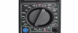
- Check the heating element circuit. We take the tester and connect its “minus” to the engine, and attach the “plus” to contact “B”. Turn on the ignition and look at the tester readings: it should show 12V. If the tester readings are less than 12V or are absent at all, then either the battery is discharged (which is unlikely) or the power circuit is open (we eliminate the malfunction). The ECU may also be faulty, but as a rule, the on-board computer immediately indicates this error.
- We check the circuit of the sensitive element. We measure the voltage between contacts “A” and “C”. minus on "C" plus on "A". The voltage should be 0.45V. If the voltage is absent or differs by 0.02 V or more, then the power circuit is faulty (you need to find and fix it) or the ECU is faulty (which is also unlikely).
You can fully check the sensor for functionality only with the help of an oscilloscope, which most car enthusiasts do not have, so I see no point in describing this situation. I will only say that to check it you will need to artificially lean and enrich the fuel mixture and look at the sensor readings. If the sensor has already traveled quite a bit - more than 100,000 km, then it can be safely replaced. Because, even if it is working, the sensitivity has noticeably deteriorated - which leads to extra costs for gasoline.
Checking the lambda probe with a tester
We take an electronic constant voltage millivoltmeter and connect it in parallel with the LZ (“+” “-” to the LZ, - to ground), and the lambda probe must be connected to the controller.
When the engine warms up (5-10 minutes), then you need to look at the voltmeter needle. It should periodically move between 0.2 and 0.8 V (i.e. 200 and 800 mV, and if less than 8 cycles occur in 10 seconds, it’s time to change the LZ. Also replace if the voltage “stands” at 0 .45 V.
When the voltage is always 0.2 or 0.9 V, then there is something wrong with the injection - the mixture is too lean or too rich. Since the oxygen sensor voltage should change all the time and jump from ≈0.2 to 0.9V.
There is another quick way to check the lambda probe . You should do this:
Carefully pierce the positive contact of the tester (black lambda wire), the other contact to ground. With the engine running, the readings should range from 0.1 to 0.9V. Constant readings (for example, 0.2 all the time) or readings that go beyond this range, or fluctuations with a smaller amplitude indicate a malfunction of the probe.
Exceptions:
- all the time 0.1 - little oxygen
- all the time 0.9 - a lot of oxygen
- The probe is fine, the problem is something else.
If you have the time and desire to bother, you can conduct several tests on a rich and lean mixture and additionally check the lambda probe sensor .
- Disconnect the oxygen sensor from the block and connect it to a digital voltmeter. Start the car and, by pressing the gas pedal, increase the engine speed to 2500 rpm. Using a device for enriching the fuel mixture, reduce the speed to 200 per minute.
- If your vehicle is equipped with an electronically controlled fuel system, remove the vacuum tube from the fuel pressure regulator. Look at the voltmeter reading. If the instrument needle approaches the 0.9 V mark, it means the lambda probe is in working condition. A malfunction of the sensor is indicated by the lack of response from the voltmeter, and its readings are less than 0.8 V.
- Do a lean mixture test. To do this, take a vacuum tube and provoke an air leak. If the oxygen sensor is working properly, the digital voltmeter reading will be 0.2 V or lower.
- Check the operation of the lambda probe in dynamics. To do this, connect the sensor to the connector of the fuel supply system, and install a voltmeter parallel to it. Increase engine speed to 1500 rpm. The voltmeter readings with a working sensor should be at the level of 0.5 V. Another value indicates a failure of the lambda probe.
Checking the voltage in the heating circuit
To check the presence of voltage in the circuit, you need a voltmeter. We turn on the ignition and connect it with probes to the heater wires (you cannot disconnect the connector, it is better to pierce it with sharp needles). Their voltage should be equal to what the battery produces when the engine is not running (about 12V).
If there is no plus, you need to go through the battery-fuse-sensor circuit, since it always goes directly, but the minus comes from the ECU, so if there is no minus, look at the circuit to the block.
Checking the lambda probe heater
In addition to measuring voltages with a multimeter, you can also measure resistances to check the serviceability of the heater (two white wires), but you will need to switch the tester to Ohms. The documentation for a particular sensor must indicate the nominal resistance (usually it is about 2-10 Ohms), your task is only to check it and draw a conclusion. The video shows this method:
Checking the oxygen sensor reference voltage
We switch the tester to voltmeter mode, then turn on the ignition and measure the voltage between the signal and ground wires. In most cases, the lambda probe reference voltage should be 0.45V.
And so I’ll summarize how you can check the lambda probe: external inspection, multimeter, warming up, oscilloscope, on-board system.
If you disconnect the lambda probe and perform the test without the car, you can only measure the reference resistance. With the element connected, you can measure the resistance and voltage on a warm engine.
How to check a lambda probe with a multimeter
The principle of checking the lambda probe is similar on all cars. The only differences are in the tension. Checking on different machines will help you understand in more detail.
For example, to check on a Skoda Octavia, we set the resistance on the multimeter to 200 Ohms. When the engine is cold, the optimal value will be 9 ohms. If you warm up the engine, the value will decrease due to conductive spraying.
After this, we measure the sensitivity of the sensor. Set the multimeter to DC mode. By connecting the red probe to the lambda probe and the black one to ground, you need to turn on the ignition. The indicators will be at the level of 0.45-0.47 V. After warming up the car, the indicators will jump from 0.1 to 0.9 V.
Checking the lambda probe on a Toyota Camry is also performed. When the ignition is on, it will show up to 0.5 V, and with constant engine operation at 2000 rpm - 0.1 - 0.9 V.
Approximately the same indicators will be found on the Ford Focus. Only if you press the gas pedal and then quickly release it, the multimeter will show 1 V. On Camry and Octavia, the value may be slightly lower - 0.8 V. This means that the lambda probe is working normally.
What and how can you check the lambda?
To check, you will need a digital voltmeter (preferably an analog voltmeter, since its “sampling” time is much shorter than that of a digital one) and an oscilloscope, if possible, the measurements will be more accurate. Before checking, you should warm up the car since lambda operates correctly at temperatures above 300C°.
First we look for the heating wire:
We start the engine, do not disconnect the lambda connector. We connect the negative probe of the voltmeter (ordinary gauge) to the car body. We “poke” the positive probe on each wire contact and observe the voltmeter reading. When the positive wire of the heater is detected, the voltmeter should show a constant 12 V. Next, using the negative probe of the voltmeter, we try to find the negative wire of the heater. We connect to the remaining contacts of the sensor connector. If a negative contact is detected, the voltmeter will again show 12 V. The remaining wires are signal wires.
Description and purpose of devices
Oxygen sensors, most often, are a galvanic system with a solid-state electrolyte, which enters the operating mode when heated above 300˚C. They are made using various materials as the electrolyte and have designs depending on their purpose.
The name λ-probes was given because this Greek letter denotes the coefficient responsible for the excess air in the internal combustion engine. With the best proportion of fuel and air in the engine cylinder (maximum efficiency is achieved with minimal fuel consumption), the ratio of the flow rate of the air mixture used to the stoichiometric (optimal): λ = 1. With this indicator, the car engine operates in an economical mode and the best efficiency of the catalyst is achieved, eliminating harmful substances from exhaust gases.
The purpose of the sensors is to control oxygen or residual fuel in exhaust gases for the operation of internal combustion engines and boilers in economical mode and to minimize harmful emissions of carbon monoxide, nitrogen oxide, and hydrocarbons using automation.
Method two
It assumes carbon deposits have burned out on the sensor. To clean the oxygen sensor using the second method, in addition to the same orthophosphoric acid, you will also need a gas burner (as an option, use a home gas stove). The cleaning algorithm is as follows:
- Dip the sensitive ceramic element of the oxygen sensor into acid, wetting it generously.
- Take the sensor with pliers from the side opposite to the element and bring it to the burning burner.
- The acid on the sensitive element will boil, and a greenish salt will form on its surface. However, at the same time, soot will be removed from it.
In what systems are they used?
Oxygen sensors allow you to measure the volume fraction of oxygen in gases present after fuel combustion in internal combustion engines and boilers operating on solid fuel or methane.
λ-probes are used in instruments that measure the proportion of oxygen in the flue gases of boilers at thermal power plants and other industrial enterprises for the best adjustment of the efficiency of fuel combustion by supplying air to the furnace, depending on the instrument readings.
Sensors are most widely used in the automotive industry for automatically adjusting the supply of gasoline-air mixture to engine cylinders.
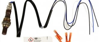
Connection wires
The pinout of the heated oxygen sensor includes four wires:
- The black wire, also called the signal wire, is connected to the controller, which reads incoming signals about the amount of oxygen contained in the exhaust;
- The two white wires are for the heating element located in the controller. In this case, it does not matter which wire is connected to the plus and which to the minus;
- The fourth wire of the VAZ 2110 lambda probe pinout is gray, this is grounding.
Electrical circuit (pinout) of the oxygen sensor
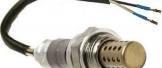
Lambda probes that are not heated may have two or three wires.
Dear customers, in order to avoid errors when sending the oxygen sensor connector (Lambda probe), in the “Comment” line indicate which oxygen sensor, your car model, year of manufacture, female or male connector.
The oxygen sensor is most often replaced by the following terms: O2 sensor, lambda probe (LZ). Therefore, if you hear these terms, then know that we are talking about the same thing.
Strict environmental standards have long legalized the use of catalytic converters (in everyday life - catalysts) on cars - devices that help reduce the content of harmful substances in exhaust gases. A catalyst is a good thing, but it only works effectively under certain conditions. Without constant monitoring of the composition of the fuel-air mixture, it is impossible to ensure longevity for the catalysts - this is where the oxygen sensor comes to the rescue.
Connective block 28122177rch with 4 contacts assembly with wires “Mom”, is an element of oxygen sensor 0 258 005 133 “Bosch” on vehicles VAZ 2108, VAZ 2109-099, VAZ 2110-2111, VAZ 2112, VAZ-2115, VAZ 2121- 214i, VAZ 2123, VAZ 2131, VAZ 2120 or Delphi oxygen sensor (DELPHI) 28122177 Delphi oxygen sensor (DELPHI) 28122177 on VAZ-21041, VAZ 2105, VAZ-21067, VAZ-21074-20, VA cars Z-21074-30, VAZ-21074-40 and their modifications injector (8V) with engine capacity 1.5L and 1.6L, EURO-2 or 3, which connects to the connector on the controller harness. Can be used to make your own cable. The contacts are already crimped onto the wires (wire length 100 mm) and inserted into the connector according to the pinout, so they can be installed on the car.
The Delphi oxygen sensor (catalog designation “DELPHI” 28122177) or “BOSCH” (catalog designation 0 258 005 133) is designed to monitor the composition of the fuel-air mixture and is installed in vehicles equipped with an electronic engine management system.
The name of the sensor comes from the Greek letter λ (lambda), which in the automotive industry denotes the coefficient of excess air in the fuel-air mixture. With the optimal composition of this mixture, when 14.7 parts of air account for 1 part of fuel, l is equal to 1 (graph 1). The “window” for effective catalyst operation is very narrow: l=1±0.01. It is possible to ensure such accuracy only with the help of power systems with electronic (discrete) fuel injection and when using a lambda probe in the feedback circuit.
What are the consequences after installing decoys?
You need to understand that any deception is installed at the risk of the car owner. If the installation was carried out incorrectly, you may encounter the following problems:
- Due to the fact that the on-board computer cannot regulate fluid injection, engine malfunction may occur.
- If the circuit is not properly soldered, it may damage the wiring.
- In the process of installing the decoy, you can damage the oxygen sensors, after which you will not even know about their malfunction (since you will already have the decoy installed).
- After such interventions (not only during flashing), the on-board computer may fail.
What is the difficulty?
An oxygen sensor or lambda probe is installed in the exhaust system of a car and serves to determine the quality of the gaseous mixture thus utilized. This element operates in very difficult conditions, so the following difficulties may arise as a result of prolonged use:
- The sensor is stuck.
- The part is in a hard to reach place.
- The edges of the product are damaged.
Considering the fact that this part is most often installed in the exhaust manifold housing, in which the temperature of the exhaust gases can reach 500 degrees Celsius, it is not surprising that the most common reason for difficulties in dismantling parts is that the oxygen sensor sticks to the metal surface of the part, in which it is installed.
The sensor may be located in such a place that dismantling it requires the use of special tools. Of course, you can always first dismantle the exhaust system, which will significantly facilitate the process of dismantling the part itself, but in this case the volume of work performed will increase by an order of magnitude.
If previous attempts to unscrew the lambda probe ended in failure and the key edges were damaged, then in this case it will be very difficult to remove the sensor.
Solution of a problem
How to safely unscrew the lambda probe will depend on the reason why problems arose with dismantling this part. If the sensor is stuck, then very often this problem is solved using a gas burner. The main condition for successful removal of a part in this way is strong heating of the collector next to the sensor. Due to thermal expansion, the seat will expand slightly, after which we remove the main part using a wrench.
To remove a sensor with licked edges, you may need a welding machine. To remove a part, you will need to sacrifice a wrench or a socket head, which, after being placed on the edges of the part, is carefully grabbed in several places. Then you should use a large lever to rotate the DC in the mounting hole. In most cases, such an operation is performed on completely dismantled elements of the exhaust system.
2014-11-12
Oxygen sensor: four wire colors
For mainstream (narrowband) four-wire oxygen sensors, two wires are used for the signal, and the remaining two are used for the heating circuit. The heating circuit is easy to find - it is two wires of the same color. Those. First we find the same colors, and the purpose (decoding) of the remaining two is determined according to the options typical for Japanese cars:
Black wires of the heating circuit
1. Blue - signal, white - ground (a very common option for Japanese cars, Denso sensors). 2. White - signal, green - ground (Honda).
White wires of the heating circuit
1. Black - signal, gray - ground (typical option for substitutes, used by Bosch sensors and others). 2. Black - signal, red - ground (occasionally happens).
We are, of course, talking about the wires from the sensor itself to the connector. Further colors can be very different.
The Jimny uses Denso's scheme: two black, blue and white.
What happens if the oxygen sensor is faulty?
If the lambda probe malfunctions, when the voltage on it does not change, the ECU begins to enrich the working mixture; it will not lean it, since this leads to more serious consequences.
A specific smell begins to penetrate into the cabin, and fuel consumption doubles. At the same time, the car accelerates much worse, since fuel fills the cylinders, and sometimes characteristic popping sounds are heard from the exhaust pipe.
Tips and tricks
Tips from more experienced car owners can save a considerable amount of time for novice auto mechanics, for example:
- If the new car is used for a short time after purchase, then to remove this part, it is enough to pre-treat the seat with penetrating lubricant.
- If the lambda probe is in a hard-to-reach place, then it should be unscrewed after installing the car above an inspection hole, on an overpass or on a lift.
- Some oxygen sensors cannot be removed without using a special key.
If the lambda probe cannot be removed, then the methods presented in this article will solve the problem. If no method is suitable, then you can always remove the manifold, cut off the sensor with a grinder, drill a hole, cut a large thread. Then install a new lambda probe into the mounting hole restored in this way.
Trouble-shooting
You can remove the lambda probe error using diagnostic scanners after eliminating the cause. If necessary, you can buy a new sensor and diagnostic device in the TopDetal.ru online store. The selection is wide and prices are lower than on the market. If you refuel with low-quality fuel, you will have to dilute it with normal fuel and remove the error after there is good gasoline in the tank.
If the contacts in the heater circuit break, you need to identify the location and solder it. If necessary, clean the contacts with sandpaper and WD-40. If carbon deposits appear on the lambda probe housing, it must be cleaned. An important condition is that you cannot use sandpaper. It is better to use liquids that corrode rust and do not leave residue on the surface.
Method one
Involves cleaning the heating element from carbon deposits (used when a malfunction of the oxygen sensor heater occurs). To implement this method, it is necessary to provide access to the sensitive ceramic part of the device, which is hidden behind a protective cap. You can remove this cap using a thin file, with which you need to make cuts in the area of the base of the sensor. If it is not possible to completely dismantle the cap, then it is possible to make small windows about 5 mm in size. For further work, about 100 ml of orthophosphoric acid or rust converter is needed. When the protective cap has been completely removed, you will have to use argon welding to restore it to its seat.
The recovery procedure is performed according to the following algorithm:
- Pour 100 ml of phosphoric acid into a glass container.
- Immerse the ceramic sensor element in acid. Do not completely immerse the sensor in acid! After this, wait about 20 minutes for the acid to dissolve the soot.
- Remove the sensor and rinse it with running tap water and then allow it to dry.
Sometimes it takes up to eight hours to clean the sensor using this method, because if you don’t succeed in cleaning the soot the first time, then it makes sense to repeat the procedure two or more times, and you can use a brush to mechanically treat the surface. Instead of a brush, you can use a toothbrush.
Recommendations
Comments 6
Bygygy. Soldering is not the same. Only welding, only hardcore =)
Seriously, no matter how much I did anything with wires in machines, I always ended up with either twisting with soldering, or crimping with soldering. And, then (if there is a need, of course), having additionally fixed it, prevent the wire from breaking along the soldering boundary - for example, by heat-shrinking it on top in two layers of different lengths, or by wrapping electrical tape in a wider area.
But I’m focusing on how it was from the factory. It’s not just that they don’t recommend soldering the lambda wires (close to the lambda itself), it’s not just that the brush cables in the brush assembly are crimped or welded, etc.? In some places it’s a technological issue – in the sense that it’s easier to produce, and in others it’s a question of reliability.
In general, I think there is no need to generalize too much =) You just need to figure out how the solder joint will feel in a particular place. Bends, vibrations of different amplitudes and frequencies, temperature, humidity, chemical exposure (salt from the road, oil, antifreeze), etc.
In the brush assembly - this is understandable; soldering is not allowed due to the presence of huge currents during operation, which in case of overload will simply melt the solder, so there is crimping and welding.
But what about the fact that soldering does not like vibration and will definitely fall apart? Only crimp, only crappy contacts! :))))) I solder everything into the car myself, nothing has ever fallen off.
I, too, am their sect of godless shareholders, Nikolai.
I could barely find the pinout of this connector on the internet. What happened was that my brother-in-law and I were changing the gasket for the sub-panel and he didn’t remove the connector while I was twisting my pants (trying) Well, in short, all the wires fell out of it. He silently collected and stuck it in, but collected it without knowing how or what. In short, I mixed up all the wires. I only found out later. Now sometimes the check pops up. Covered the sensor?
Types of sensors and temperature conditions of their operation
There are two types of oxygen sensors on the market – titanium and zirconium.
The first are made on the basis of titanium dioxide, and the second - on zirconium dioxide.
They are distinguished from each other only by design features; the operating principle is the same.
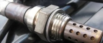
The basis of the device is a ceramic element made of the above-mentioned zirconium dioxide (ZrO2) or titanium dioxide (Tio2), coated with a platinum mesh.
One part of the element is located in the exhaust pipe and is in contact with the exhaust gases, and the other is outside, in contact with atmospheric air through the wire connections.
The temperature at which the lambda probe begins to function varies from 300 to 400 °C, the dangerous limit is 900 - 1000 °C, beyond which the device can overheat and fail. Operating temperature when moving is about 600 °C.
In modern lambda probes, but not all, a heating element is structurally provided, which, when starting the engine on a cold one, will warm the device to an operating temperature of 300 - 400 ° C.
A distinctive feature is the presence of three or four wires, two of which are white (on Japanese cars they can be black) going to the heater.
Such devices can be installed in the exhaust pipe at a considerable distance from the engine, since they do not require intense heating by exhaust gases.
There are no heaters in two or one-wire oxygen sensors, so they are installed as close to the engine as possible, usually in the exhaust manifold, but so that the lambda probe does not fail due to overheating.
For many types of sensors, especially those installed on German cars, but except for Japanese ones, the black wire is the signal wire, and the gray (may not always be) is the signal ground.
On oxygen sensors installed on Japanese cars, the wires have an individual color scheme for each model, so this point needs to be clarified each time.
But there is still one plus: lambda probes, which replace failed analogues, apply only to Japanese cars, have a constant color scheme of wires: the signal signal is blue, not black, the signal ground is white, not gray, and for the heater There are two black wires, not white as usual.
Why exactly 300 °C? It is after this indicator is exceeded that the ceramic element of the device, which can safely be called a solid electrolyte, begins to pass oxygen ions through itself, which collect on the platinum electrode grid.
Imagine two 5-liter containers (canisters) filled with water, standing on the same level and connected to each other by a hose, in the middle of which there is a faucet.
If you just open the faucet, where will the water flow? That's right, nowhere. And if you lift one of the canisters, where? That's right, into the canister that is located below.
A similar principle works in the case of a lambda probe. Opening the tap means the temperature on the ceramic element exceeds 300 °C.
And the flow of oxygen ions through it is ensured by the formation of a potential difference at its ends (raising one or the other canister), the greater the difference, the stronger the voltage (the higher the capacity, the stronger the water flows).
On the side of the sensor that is in contact with atmospheric air (reference), the oxygen content is small and, as a rule, changes only when the vehicle’s operating conditions change (mountains, quarries, etc.), the potential there is small, but it is constantly present.
And on the side of the device that is screwed into the exhaust pipe, the volume of oxygen can vary from small to significant.
But you need to understand that a small amount of O2 in exhaust gases is considered normal, since this ensures complete combustion of the fuel in the exhaust manifold and protects the catalyst in the event of a strong over-enrichment of the fuel mixture (unburned fuel is thrown into the manifold and burns out there).
If the amount of O2 in the exhaust gases is equal to the oxygen contained in the atmosphere, then there will be no potential difference (if this is associated with canisters, then they will be at the same level), and the reference voltage coming from the control unit will be exactly 0.45 volts - level lambda is equal to 1.
Let's say the volume of oxygen in the exhaust gases is significantly lower than atmospheric.
Due to the potential difference, an electric current is formed that flows from the inside of the galvanic cell, in contact with the reference air, to the outside (the “+” value). Its value increases the reference voltage from 0.45 volts from 0.5 to 0.8-0.9.
The ECU sees that the mixture is rich (lambda level less than 1) and makes adjustments.
If the oxygen level in the exhaust gases is high (more than atmospheric), then the potential difference will change, the electric current will flow in the other direction (the “-” value), reducing the reference voltage to 0.1 - 0.3 volts. The ECU will see that the fuel mixture entering the cylinders is lean - the lambda level is greater than 1.