The Hall sensor (current, phase) records fluctuations in magnetic fields, especially those arising with currents, and their intensity, which is required in an extremely wide range of devices for monitoring the position of their nodes. In a smartphone, current sensors ensure the operation of the compass and smart cases. In cars, the angle of camshafts, crankshafts, ignition sparking moment, wheel rotation parameters, and approach to objects are measured. Increasingly, phase sensors are installed instead of a reed switch. Let's look at what a Hall sensor is, how it works and the types with a description of where they are used.
Basic information
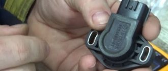
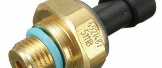
Let's start with basic information: where is the Hall sensor located, what is it, what is it for. A “naked” sensor is a small meter (sensor, detector), almost always black (the color depends on the manufacturer’s preferences), several millimeters in size. Automotive products have a relatively large plastic protective box, a “chip” with a cable with a connection connector.
The phase sensor monitors magnetic fields and their parameters (strength), while producing specified operating algorithms (closing contacts, etc.).
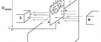
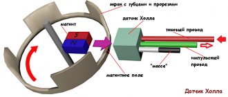
The sensors in question were named after the scientist Hall, who discovered that a potential difference (Hall voltage) occurs when objects with direct currents are placed in a field.
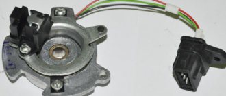
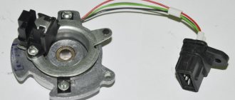
The car current sensor is located in the distributor - a unit for connecting spark plugs; it is hidden by a plastic chip with three wires and a connector for them. On other devices it can be placed anywhere. Usually on printed circuit boards it is a tiny black box, usually with 3, less often - 4 legs. Linear Hall sensors resemble a microcircuit. The product is also identified by its markings; the designations are in reference books of radio components (common ones are S41, 41F, U18, 3144, 44E, 49E).
When current flows in one direction, electrons are deflected in conductors placed perpendicular to the field. Their areas have an uneven density of particles, this is the potential difference recorded by the Hall sensor. It becomes possible to analyze voltage at right angles to current.
There is also a simplified Hall effect sensor, as, for example, in smartphones: only with the function of confirming the presence of magnetic phenomena, the tension is not analyzed. Based on a unit that includes a sensor and a magnetometer, the phone is equipped with a compass option.
How it works
Operating principle of using a Hall sensor:
- When current passes, electrons move linearly through the sensor.
- When exposed to a field, particles with a charge are deflected by the Lorentz force along a curved path.
- Negatively charged elements, also known as electrons, are attracted to one side of the Hall sensor, and positive ones (holes) are attracted to the other.
- The described accumulation in different segments creates different voltages, this is the potential difference. The proportionality of the resulting voltage to the electric current and field strength is direct. These final phenomena are tracked by the sensor; the principle is used to determine the position of the objects being serviced under their control.
Where are they used?
Phase sensors began to be installed in structures about 75 years after their invention, when technologies for creating semiconductor film materials became available.
Typical areas of application of Hall sensors:
- the first area where use began was mechanical engineering, for measuring the angles of camshafts, crankshafts, and detecting sparks on ignition units;
- switches (non-contact type), analyzers for levels of substances, speed of rotation of blades, devices for remote detection of currents;
- scanning magnetic symbols;
- as a replacement for reed switches (circuit breakers with closing contacts via a magnet). In this area, the described devices are the most common due to the large number of devices: microelectronics, equipment from headphones to manipulators, keyboards, in elevators, security equipment (doors, locking elements).
On a smartphone
The hall sensor in a smartphone is used for the following purposes:
- as part of a compass, magnetometer;
- for monitoring the closing/opening of a case with a magnetic latch by tracking field weakening/increasing;
We will describe why a hall sensor is needed in a smartphone on the cover. When the magnet moves away from the detector, there is an impulse to activate the display, when closer, it turns it off. A variety of such cases is a separate type of product, usually called Smart Case. There are also additional functions, their operating principle is as follows: if a cover without windows near the display is used, then the detector turns off the screen when it is closed, and automatically activates when it is opened. If there are windows, switching of contents to the display is initiated. On the visible area there is a clock, etc., on the entire display there is all the information.
Not all smartphones have the described improvement, and manufacturers do not always indicate it in the list of options, so you need to clarify this parameter. But if in the recommended accessories there is a note about those suitable from the Smart Case category, then this option is present.
Measuring linear or angular movement
In most applications, LDCs are used in conjunction with permanent magnets to measure the movement of objects. This is due to the fact that in order to maintain maximum linearity it is necessary to ensure a large change in the magnetic field when the distance between the LDC and the reference point on the moving object changes. A permanent magnet must be selected with the highest possible field strength, for example SaCo or AlNiCo.
There are several options for the relative position of a permanent magnet and LDC in systems for measuring object movements. The simplest method is a linear arrangement of the LDC and magnet on the same axis so that the magnetic field lines intersect the sensor at an angle of 90°. With this arrangement, there is a highly nonlinear relationship between the output voltage of the LDC and the distance between it and the magnet (Fig. 8). For relatively small movements, the deviation from linearity is small and there is no need to resort to additional linearization. Otherwise, it is necessary to use an additional circuit for linearizing the distance-voltage characteristic.
Rice. 8
The second option is to locate the LDC and magnet in parallel planes. With this orientation, the system has a zero field point, which makes it possible to obtain additional information about the direction of movement according to the sign of the output voltage (for example, to the right - an increase in voltage, to the left - a decrease (Fig. 9)). As can be seen from Fig. 9, the central region relative to the zero displacement point has high linearity, which can be successfully used in applications such as potentiometers, air correctors (pneumatic valves), throttle position sensors, etc. By the way, in this embodiment, due to the large amplitude changes in the magnetic field strength near the zero point, the output voltage of the LDC also has a large range, which simplifies subsequent signal processing.
Rice. 9
The third option is to locate the LDC between two complementary magnets (Fig. 10). The complementary fields of the two-magnet system provide good linearity with high slope characteristics. This system also has a zero movement point, which allows information about the direction of movement. The disadvantage of the described option is the rather small range of movements in such a system, which limits its scope of application.
Rice. 10
Most of the considered options, to one degree or another, require linearization of the dependence of the output signal on distance. This can be implemented using an ADC and a microcontroller if the device being developed provides for subsequent digital control. If the result is an analog signal that is linear with distance, the linearization process can be easily implemented using an Anadigm programmable analog integrated circuit (PAIC) [1]. In this case, it is enough to remove the experimental dependence of the transformation function once and enter it in the form of a table of coefficients in the development environment. In addition to linearization, PAIS can, if necessary, implement additional signal processing (amplification, filtering, zero detection, etc.).
Types of Hall sensors
For convenience, we consider the varieties in a table:
Where and why are analog devices used:
- in ABS (anti-lock braking systems);
- motor control (protection, indication);
- devices for detecting power, vibration, ferrous metals in detectors;
- motion monitoring (approach/distance, for example, when parking);
- measurements of flow parameters of substances and structures;
- when adjusting voltage;
- phase sensors located on current clamps (Tong Testers) are involved in measurements.
Digital:
- The Hall sensor is responsible in the car for monitoring the position of the crankshafts for the ignition angle of spark plugs and valves;
- in optics controls the position of the lens;
- determining the placement of seats in the car, the condition of seat belts and airbags;
- wireless communications, mobile computers (smartphones, tablets, laptops);
- in instruments for determining pressure;
- sensors in the parking sensors system, similar devices for fixing approaching/removing distances;
- to analyze flow parameters.
Advantages and disadvantages
Pros:
- universality (they simultaneously determine position, direction, and so on);
- wear resistance. There are no moving parts, they are solid state, rugged devices, providing extreme durability;
- almost complete independence from the need for maintenance;
- The Hall effect current sensor operates under vibrations, in dusty, humid, aggressive conditions, and at high temperatures.
Minuses:
- standard devices have a maximum distance to the measured current of about 10 cm. But it all depends on the magnet: if it is powerful and creates a wide field, then the distance increases;
- a characteristic “disease” is accuracy, since there is a dependence on the magnetic field, and other external similar phenomena can introduce distortions. The same applies to high temperatures, since they change the resistance of conductors, and accordingly, the mobility of charge carriers, but here sensitivity suffers. However, this is rare or the effect is negligible; in general, it does not particularly affect the work.
Operating principle and types
The use of sensors in various devices (in a tablet, in particular) is explained by their ability to respond to field changes and turn off when the magnetic cover of the case is closed. Thanks to this property, they are also installed in washing machines, allowing you to control the rotation speed of the drum. To put it in simple terms, the Hall sensor is used here as a tachometer.
Historical reference
To understand the principle of operation of this element, you will need a short excursion into history. In 1879, the American physicist Hall discovered an interesting phenomenon related to the behavior of a current-carrying conductor in a magnetic field. The test showed that if a current is passed through a copper plate placed between the magnets, then a potential difference appears on its side faces. A natural question arises: how to check this voltage at home?
It turned out that in practice it can be measured with a multimeter or any other device that has appropriate limits. The same can be done with any suitable tester or similar device.
Connecting the meter confirms that moving electrons under the influence of a magnetic field are deflected to the side (perpendicular to the direction of their movement).
Important! The magnitude of this deflection, or potential difference, is proportional to the “power” of the magnets and the current through the plate.
On this basis, Hall concluded that such a conductor was a good means for measuring the magnetic field. The operation of a special sensitive element called a Hall sensor is based on this effect. Having understood how it works in each specific device, you can be confident in the final understanding of its operating principle.
Classification
It is important to understand what types of Hall sensors there are, and by what principle they are usually classified. Depending on the features of operation and why it is needed or intended, the Hall sensor can have different designs. One of the varieties is analog devices that produce a continuous signal at the output.
In contrast, a digital element has only two discrete states (“zero” and “one”). This type of device can be unipolar or bipolar. The first of them is triggered when a field of any polarity is detected and turns off when it disappears. That is, a unipolar digital sensor reacts only to the absence or presence of magnetic intensity. The considered features of each of the subtypes also help to understand what it is - a Hall sensor.
Unipolar sensors switch to “one” only when the field reaches a threshold level and are not able to detect its presence at low voltages. This property is a significant disadvantage of such devices, significantly limiting the scope of their application. The bipolar sensor is triggered by taking into account the polarity of the magnetic field, one of which turns it on and the other turns it off.
The conventional graphic designation of devices of this class is shown in the photo below:
In cars
Hall sensors have been installed in vehicles since the 70–80s of the last century, when electric ignition began to be introduced instead of contact ignition. Operating principle: the motor shaft rotates with its impeller passing through the housing slots, which is detected by the detector, which sends a command to the switch, which unlocks the transistor, which supplies voltage to the ignition element with the winding. The latter creates a high voltage for the spark plug.
Design
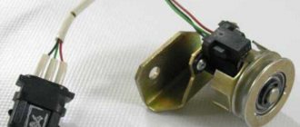
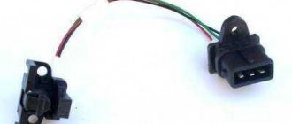
A box, a “chip” with three contacts, three wires and a connection connector - this is a classic device for automotive Hall effect sensors. Only minor details differ between models. This design, taking into account the nuances of the objects being served, can be considered as a general model.
Hall sensor, device, circuit:
- “ground” (car body), this is “–” or working zero;
- “+”, working serviceable products have about 6 V there;
- contact for transporting the pulse to the switch.
There are the following advantages of current sensors for electronic ignitions:
- there is no constantly burning volumetric contact unit;
- on a candle above 30 kV versus 15 kV, which is much better;
- sensors are installed on brake systems, anti-lock braking systems, and tachometers, so there are important additional advantages: the performance of the internal combustion engine increases, all systems of the car accelerate and work more efficiently. As a result, ease of use and safety increase.
Search on the site
This is the Hall generator.
Everything is very simple. The next step is to carefully unsolder the legs of the element from the test circuit and connect it to the standard connector contacts.
You turn on the ignition.
The sensor circuit includes a power supply that converts unipolar supply voltage into bipolar power supply to the circuit. Pull out the pin using pliers. In a working device, the voltage will vary from 0.4 V to 11 V. Thanks to simple techniques, the motorist will save his time on repairs, and also eliminate unnecessary waste of money.
The impulses arise due to the fact that the slots do not go through the same distance, but through different ones, that is, they alternate. Replacing the sensor: instructions for motorists To install a new ignition sensor, you need to correctly remove the one that has failed. Resistors R1, R2 set the output current of our pulse sensor.
Disconnect the distributor cover. The third wire is used to transmit a signal, the polarity of which changes relative to the common power wire. Connect a voltmeter to the sensor output. The use of such a sensor will require monitoring the speed of the output shafts of gearboxes, monitoring the direction of rotation of two or more synchronized mechanisms, and accounting for fluid flow.
Magnetic field sensors. Hall sensors in MK circuits
We check the work again with a tester and at this point the work on repairing the Hall sensor can be considered complete. If it is impossible to install a working sensor, you can use a simple device that will duplicate its operation. But the Hall generator is most widely used in the automotive industry - for measuring the position of camshafts and crankshafts, as a non-contact electronic ignition and for other purposes. The first devices turned out to be quite bulky and not very ergonomic.
The use of neodymium magnets, the strongest permanent magnets, allows you to fit a sufficient number of small-sized magnets on the disk. Typically, replacing a Hall sensor consists of several steps: First of all, the distributor is removed from the machine. Also, do not exclude other ignition system malfunctions found in cars. The new Hall sensor is installed in the reverse order. The easiest way is to replace the device with a working one. installation of ignition with a hall sensor on a motorcycle. BASHKIRIA STERLITAMAK
Connecting large electrical loads
The output power of the Hall sensor is very low (10–20 mA), as a result of which it cannot directly control high electrical loads. The problem is solved quite simply: the connection is made by adding an NPN transistor to the device, through which current flows to the output. The specified part acts as a receiver; when it is saturated, it is activated as a switch. The transistor grounds the output contact, thus closing it when the flux density of the set values for “on” increases.
There are various configurations of the transistor switch, but the main thing is that the device provides a 2-cycle output, allowing it to draw the required current to control large loads.
Current sensor failure
Frequent breakdowns and signs of a Hall sensor malfunction:
- the engine does not start, interruptions in starting;
- unstable idle;
- At high speeds there is jerking (a common sign), the vehicle stalls.
A faulty sensor can short out to the housing, causing ignition problems.
The disadvantage of diagnostics is that the listed symptoms may also be characteristic of failures of other components. The circumstance is partly mitigated by methods that are not too complex, and can be done by users with basic knowledge of technology.
How to replace the sensor yourself?
Not every car enthusiast has time to manually repair sensors. It’s easier for them to buy a new one and install it instead of the old one. This procedure is carried out as follows:
- First of all, you need to remove the terminals from the battery;
- The distributor is removed, the block with wires is disconnected;
- The distributor cover is removed;
- Before completely dismantling the device, it is important to remember how the distributor itself was located. It is necessary to align the timing marks and crankshaft marks;
- The distributor shaft is removed;
- The hall sensor itself is disconnected;
- A new one is installed in place of the old sensor;
- The block is assembled in the reverse order.
The latest generation of sensors have a long working life, so frequent replacement of the device is not required. When servicing the ignition system, you must also pay attention to this tracking device.
Hall sensor check
There are several options for how to check the Hall sensor and how to analyze the functionality. Choose the most accessible method or one that suits the prevailing conditions - all methods are effective
You need to know what a Hall sensor looks like; checking also means knowing how the pinout works.
Availability simulation
The procedure is the fastest, suitable when there is power to the electric ignition, but there is no spark.
Order:
- The 3-pin block is removed from the distributor.
- Turn on the car ignition.
- Connect (close with a piece of wiring) contacts (terminals) 3 and 2. The first is “–”, the second is “+”, for the signal.
- Move the wires, quickly connecting/disconnecting them from the contacts. There is a spark - the sensor is broken. The high-voltage wire is held near ground.
Checking with a multimeter
Testing the hall sensor with a multimeter is popular; it makes it possible to determine whether the power circuit itself in the product is working properly.
How to check the hall sensor on a VAZ with a tester:
- Convert the tester to voltage analysis (voltmeter) with a range from 0 to 15 V.
- Put the wheel in fourth gear and lift the wheel slightly with a jack (enough to spin it).
- Connect the tester to the sensor, turn the wheel and watch the display.
- Measure the output parameters: a working copy has them in the range of 0.4–11 V.
To check if there is an open circuit, set the tester to the “continuity” mode. One probe to the contact on the chip, the second to the corresponding sensor leg. This method only tests the cable cores, and not the internal structure of the sensor itself. There is no break - a buzzer (if there is such an option) and a jump in numbers close to zero (0.001 and the like); there is a break - 1.
Options for testing circuits with a multimeter and voltmeter:
Replacement with a working copy
You can supply the work item if you have a spare one, or borrow it. If the problem remains, then the old copy is broken, but it is advisable to make sure that it is completely broken and insert it again, having first cleaned the contacts.
Complex method
This procedure for checking a Hall sensor is more complicated than the previous ones, but if you have average knowledge of electrical engineering, it’s easy to apply. The point: check if there is resistance.
To implement it, you need to make a simple knot. Assemble a circuit with an LED, a resistor (1 kOhm), and a Krona battery (9 V). A graphical diagram is enough to understand:
Do-it-yourself Hall sensor with an auxiliary device is checked as follows:
- The diode leg is equipped with resistance (a resistor is soldered), 2 wires are connected to it, preferably longer. Remove the distributor cover, snap off the distributor and plug box. They analyze the electrical circuit: tester probes (a voltmeter will do) to terminals 1 and 3, then ignition. Serviceability - 10–12 V on display;
- similarly, the constructed structure is connected to the same terminals. If the polarity is correct, light will appear; if not, the wires are rearranged;
- We do not disturb the wiring on terminal 1; the end with 3 is thrown onto the free 2;
- turn the camshaft (manually, with the starter): the light blinks - everything is in order, if not, you need to change the Hall meter.
On most vehicles, Hall sensors are tested as closely as possible, as described.
Distinctive features in case of DC malfunction
Malfunctions in the operation of the sensor have various manifestations. Determining them by external signs without opening them is not always possible. Below are some of the most common symptoms of a Hall sensor malfunction:
- the engine does not start or starts poorly;
- unstable operation at idle;
- when driving at high speeds, the car “jerks”;
- The running engine stalls for no apparent reason.
If one or more of the above symptoms appears, the Hall sensor should be checked for defects.
Hall sensor Audi Volkswagen
Replacement
Let's look at the standard procedure for replacing a VAZ hall sensor. The process is simple even for novice car enthusiasts.
The procedure for replacing the Hall sensor:
- Remove the distributor and dismantle its cover.
- Align the marks of the gas distribution mechanism and crankshaft.
- Remove the fasteners with a wrench. In this case, it is recommended to mark and remember (take a photo with a smartphone) the location of the distributor.
- Clamps and stoppers in the housing are also dismantled.
- Remove the shaft from the distributor.
- Disconnect the terminal contacts, unscrew the mounting bolts, and pull out the detector through the slot.
- Connect the sensor correctly - proceed in reverse order.
There is no connection diagram in the car as such, since the sensor has a power cable with a plug, that is, the pinout is already there, and the chip is equipped with “foolproof protection” and keys (protrusions) that make incorrect installation impossible. The detector box has holes for mounting bolts.
In other devices, the Hall effect sensor is soldered according to the location of the legs and contacts under them on the board. If you take a “bare” sensor, however, and if there is a housing, the arrangement of contacts is similar. The required leg for soldering to the board is determined simply, as in the diagram below.
Where is it located and what does it look like?
The Hall effect has found application in many car systems, such as:
- Determines the position of the crankshaft (when the piston of the first cylinder is at the top dead center of the compression stroke);
- Determines the position of the camshaft (to synchronize the opening of valves in the gas distribution mechanism in some models of modern internal combustion engines);
- In the ignition system breaker (on the distributor);
- In the tachometer.
During the rotation of the motor shaft, the sensor reacts to the size of the teeth slots, which generates a low voltage current that is supplied to the switching device. Once in the ignition coil, the signal is converted into high voltage, which is necessary to create a spark in the cylinder. If the crankshaft position sensor is faulty, the engine cannot be started.
A similar sensor is located in the contactless ignition system breaker. When it fires, the windings of the ignition coil switch, allowing it to produce a charge on the primary winding and discharge to the secondary.
The photo below shows what the sensor looks like and where it is installed in some cars.
In the distributor
Crankshaft sensor
Camshaft sensor
Tachometer sensor
Hall sensor in the electric motor
Repair
There is no point in repairing Hall sensors, since the cost of this will exceed its cost, which is in the range of $3–5.
If, out of curiosity, someone wants to do repairs, then you can try to do this for automotive products, but the repair will not concern the very core of the sensor, but the “chip” and the cable: the capacitor often burns out, it and the wires can be resoldered. The cause of the malfunction may lie in soured contacts; they are cleaned.
Trouble-shooting
If you want to repair the hall sensor yourself, you will first need to purchase a so-called logical component. You can select it according to the model and type of sensor.
The repair itself is carried out as follows:
- Using a drill, a hole is made in the center of the body;
- The wires of the old component are cut with a utility knife, after which grooves are laid for new wires that will be connected to the circuit;
- The new component is inserted into the housing and connected to the old contacts. You can check the correct connection using a test diode light with a resistor on one contact. Without the influence of the magnet, the light bulb should go out. If this does not happen, then you need to change the polarity;
- New contacts must be soldered to the device block;
- To ensure that the work was carried out correctly, the new sensor should be diagnosed using the above methods;
- Finally, the housing must be hermetically sealed. To do this, it is better to use heat-resistant glue, since the device is often exposed to high temperatures;
- The controller is assembled in the reverse order.