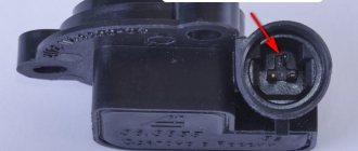
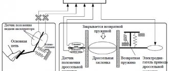
In a system with an EDP (electric throttle pipe), two TPS are used. Each such sensor is a potentiometric-type resistor, one of whose terminals is supplied with a reference voltage (3.3 V) from the controller, and the second is supplied with ground from the controller. From the pin connected to the moving contact of the potentiometer, the TPS output signal is supplied to the controller.
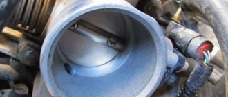
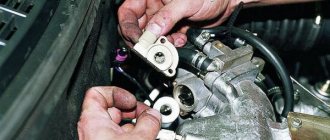
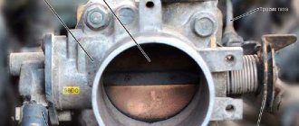
The sensor is located in the throttle body near the air intake pipe. An idle speed regulator is installed next to it.
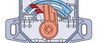
Throttle valve in pre-start position
The controller's task is to control the position of the throttle valve through an electric drive, which is set by pressing the accelerator pedal. TPS is needed just so that the controller can monitor the current position of the throttle valve.
When the ignition is turned on in the car, the damper is set by the controller to the pre-start position. At this moment, the degree of opening determines what temperature the liquid in the cooling system has. When the throttle valve is in the pre-start position, the output signal on the sensors from the first terminal should be about 0.39-0.52V , and from the second - 2.78-2.91V .
Throttle valve at rest
If within 15 seconds from the moment the ignition is turned on, the engine is not started and the accelerator pedal remains at rest, the controller will stop the supply of power to the electric throttle drive, as a result of which the damper will move to an almost closed position (no more than 7% opening). In this state, the output signal power of the first sensor will be 0.5-0.6V , and the second - 2.7-2.8V .
If the engine and accelerator remain at rest for the next 15 seconds, the throttle will automatically enter test mode. This means that it will move to the zero position until it is completely closed and then moved to the pre-start position, after which the electric throttle drive will be completely de-energized until the next ignition is turned on.
If a problem is detected in the sensor circuit, the controller completely stops supplying voltage to the throttle actuator, while simultaneously storing the error code in memory and displaying it on the dashboard. In this case, the throttle valve is always set to 6-7% opening
.
Regardless of what position the throttle valve is in, the output signals from both sensors should add up to 3.3V . The maximum permissible deviation is 0.1V .
Installation and causes of sensor failure
Installation is carried out in the reverse order of removal. Note the foam ring needed for the seal. Damage to it is unacceptable. Therefore, it is advisable to replace the broken ring with a new one. The better the quality of the ring, the better the TPS will work and the lower the likelihood of new breakdowns. But here the question arises: why could such a simple sensor break? There can be many reasons. Here are the most common:
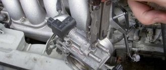
Location by car
- partial or complete wear of the substrate;
- erasing the spray;
- failure of the movable core with contacts.
The result is that there is no way to obtain a linear increase in voltage at the signal pin. After assembly, no settings or adjustments are needed: the microcontroller system perceives the closed throttle valve as the starting point.
Repairing sensors is extremely difficult, since it becomes necessary to create a new contact layer. This cannot be done at home, and not every service station has such capabilities. If you look at the cost of similar sensors for a Lada Kalina car, it turns out that it is easier to buy and install a new one. Another advantage (besides the low price) is that replacement takes no more than five minutes. And this is provided that you simultaneously clean the contacts and the throttle valve.
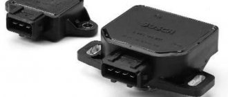
Which TPS to install on your Lada Kalina car is up to you to decide. But it’s worth talking about which designs are preferable. I would like to install the sensor once and forget about problems with it for a long time. The simplest and cheapest potentiometers can boast only of their price. But their service life is not very long. Such sensors were installed on the AvtoVAZ assembly line. But contactless devices, although they cost twice as much, have a much longer service life. Therefore, if you look from the point of view of reliability, it is best to use magnetoresistive sensors.
TPS malfunctions
Owners of Kalin and Prior may encounter a large number of TPS faults. In each individual case, the nature of the breakdown affects the operation of the motor differently, so the symptoms may vary. Let's look at the main signs of sensor malfunction:
- floating speed when starting the engine, and then recovery during warm-up;
- jerks during acceleration;
- power reduction;
- uncontrolled increase in speed;
- increased fuel consumption;
- The motor is unstable and stalls.
If you have problems with the engine idling, you should not rush to change the idle speed control; the problem often lies in the throttle position sensor. It needs to be checked first.
Most often there are 3 main causes of malfunction:
- the coating layer on the mechanism wears out;
- the movable core stops working;
- The regulator substrate is partially or completely worn out.
Causes
Usually the reason for carrying out work is interruptions in the functioning of the power unit - idle speed “floats”, or even the engine stalls or does not start.
IMPORTANT! The manufacturer states that the throttle assembly is non-separable, and therefore its repair in case of damage is excluded. A new component needs to be installed.
As for the regulations, it is recommended to clean it once every 50,000 km.
How to check throttle sensors
The first signal indicating the need to determine a malfunction of the TPS on Kalina or Priora (as well as other injection cars) is the lighting of the “Check Engine” icon. Using a diagnostic scanner, you can find out the error code, and then use a multimeter to take the necessary measurements of voltage and changes in resistance when moving the damper.
Scanner check
Throttle position data
We connect the autoscanner and look at two values in the OpenDiag application:
- “Throttle position sensor 1”;
- “Throttle position sensor 2”.
The indicators should be 4.3 and 0.7V , respectively.
To check, you need to press the E-gas pedal to the floor. The indicators will change by 0.8 and 4.2V , respectively. Ideally, the sum of these indicators should be 5V. If a malfunction is detected, the program displays error code P2138 or P2135. This means that a breakdown has occurred in one of three components: the TPS, the electronic gas pedal position sensor, or in contacts “A” and “B” of these sensors.
Checking with a multimeter
Sensor testing
First, the current is checked at the two contacts of the sensor. This is done in order to find out the condition of the wires, since they could simply break.
When you turn on the ignition, the multimeter should display a voltage within 5V , with a probability of deviation by 0.5V . You can check the sensor without dismantling it.
We disconnect the terminal from the battery, remove the wires with the chip, place the wire on the pin that transmits the signal to the on-board computer and mount the chip in place.
We attach the multimeter probe to the additional wire on the other side, and connect the second probe to the negative terminal of the battery. After this, the terminals need to be put on the battery, but the engine must not be started.
Sensor readings with the damper closed
We set the device to a mode that measures direct current and smoothly press the gas pedal. When you gradually press the floor, the voltage indicator should change gradually. When the damper is completely closed, the voltage will be from 0 to 0.5V . When it is fully opened, the indicator will reach 5V . If you notice sudden voltage surges, the sensor is faulty.
In addition to measuring voltage, there is a way to test the sensor by measuring resistance. To do this, you need to set the appropriate mode on the multimeter and remove the TPS.
After unscrewing the two screws with a Phillips screwdriver, disconnect the wire and remove the sensor. To connect to the negative contact and the output of the signal wire, we use additional wires.
We smoothly turn the mount on the sensor, thereby simulating the movement of the throttle valve.
When the damper is in the closed position, the resistance will be 1.5 kOhm. When fully open, the resistance changes to 7.5 kOhm.
The resistance value should also change smoothly, like the voltage.
Fuel pressure sensor (FPS)
Used to transmit information about pressure in the fuel system to the ECU. DDTs are mounted on different types of engines, running on both gasoline and diesel (with Common Rail). Installation location: fuel rail of the power unit.
The task of DDT is to maintain pressure at the required level and ensure normal operation of the power unit. This ensures normal power and noise levels. Sometimes a car has two sensors - high / low pressure.
DDT has a simple device:
- sensor component (metal membrane);
- strain gauge (an element that, when deformed, leads to a change in its electrical resistance).
The thicker the membrane part, the higher pressure DDT can withstand.
As for strain gauges, they are needed to convert mechanical actions into electrical commands. In normal mode, a voltage from 0 to 80 mV is generated at the output.
If this parameter is exceeded, a special valve in the fuel system is activated, ensuring normalization of pressure.
The breakdown of DDT manifests itself in the following signs:
- ignition of the Check Engine lamp on the “tidy” (P0191 in the scanner);
- excessive consumption of fuel;
- difficulties starting the power unit;
- loss of engine power;
- shutdown on XX;
- fuel leakage from fuel hoses/rail.
If any of these symptoms appear, it is advisable to check the computer for errors.
The reasons for the breakdown of DDT include:
- damage to the internal elements of the sensor;
- wiring fault;
- contamination of the mesh on the regulator due to debris getting into the fuel, for example, when the fuel filter did not cope with the job;
- wear/wedge of the locking element inside the pressure regulator;
- incomplete fit of the DDT casing to the rail;
- ECU failure.
To check the old sensors, it was enough to turn off the “return” of the fuel supply for a while on a cold engine. If the engine stops running, it means the problem is in the DDT.
On new devices you need to measure the voltage, which should be about 5 V.
It is also worth checking the voltage between the “minus” of the chip (black wire) and the “plus” of the battery (red wire). If the voltage is about 12 V, then the DDT is working. When checking with a pressure gauge, the pressure should be about 2.5-3 atm.
TPS repair
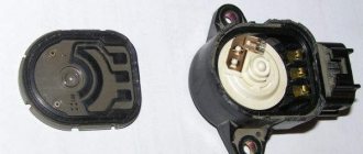
Rheostat and sensor contact groups
If the throttle sensor fails, you can try to repair it, but they are often simply replaced. Repair and restoration of operability are allowed only if the contact groups or rheostat tracks have oxidized.
To do this, it is necessary to dismantle the TPS cover. A rheostat is located under it in an inverted state. It needs to be carefully bent, after which the tracks and 2 contact groups (sliders) that come into contact with the tracks will be visible. Bend the sliders away from the body so that they fit more tightly to the rheostat. You can learn more about TPS repair by watching the video:
Throttle Position Sensor Repair
To clean the contacts and current collector tracks, wipe with alcohol.
After this, the sensor must be checked for resistance by connecting probes to the central and left contacts of the device. If, during operation of the rheostat on the multimeter, the resistance readings do not smoothly increase and decrease, but jump chaotically, then the sensor needs to be replaced.
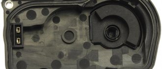
Operating principle of the sensor
The Kalina throttle sensor is used to transmit a signal to the engine ECU. This part is a potentiometer, the maximum output voltage of which does not exceed 5 Volts. The element consists of a housing, inside of which there is a variable resistor. The positive power wire is connected to one of the contacts of the product, and ground to the second. An output conductor is connected to the third terminal, the voltage of which depends on the angle of the throttle valve. The potential difference is changed by moving the moving part of the third contact along resistive tracks.
The moving contact of the potentiometer is installed on the throttle valve axis, so a change in the position of this element is instantly responded by a change in voltage at the output contact.
How to Replace a Throttle Position Sensor
Since the TPS on Priora and Kalina does not have a long service life, most owners of these cars have to change it. Therefore, we will consider all 3 stages of replacement: dismantling, installing a new one and resetting the error in the ECU memory.
Replacing TPS
Step by step replacement:
- check if the ignition is turned off;
- remove the connector (chip) with wires;
- Use a Phillips screwdriver to unscrew the bolts;
- We take a new TPS and before installation we correctly position the foam rubber gasket;
- install a new damper sensor, turning it until the holes match;
- tighten the screws back;
- install the chip in its place.
The process of replacing a sensor on a Priora
Bolt for adjusting the damper position
To reset the error stored on the ECU, remove the terminal from the battery for 10 minutes or reset it programmatically. After replacement, the new throttle position sensor is not adjustable. You can only set the damper closing level. We unscrew or tighten a special bolt that limits the degree of closure.
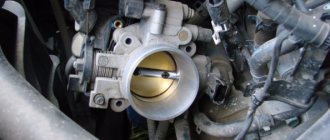
Removal
Cleaning the Lada Kalina throttle assembly begins with its dismantling.
Note. There is an opinion that it is not necessary to remove the component. This is true, but in this case all the carbon deposits will pour into the engine!
First of all, you need to turn off the engine, let it cool, and then remove the terminal from the battery.
Then the clamps securing the hoses and pipes are unscrewed:
- Small – 4 units;
- Large – 1 unit.
The plugs are disconnected from two sensors - TPS and IAC.
The accelerator cable is removed.
To prevent antifreeze from leaking, the hoses must be fixed at the top. In addition, you can insert M12 bolts into them.
In the end, all that remains is to unscrew the 2 nuts using a 13mm socket and remove the remote control.