Other symptoms of a faulty mass air flow sensor:
1)Check Engine error appears; 2) Increased fuel consumption; 3) Poor starting when hot; 4) The car began to accelerate slowly; 5) Engine power lost. 6) Etc.
How to check the mass air flow sensor
Method No. 1: Disable the mass air flow sensor.
Disconnect the sensor connector and start the engine. If you turn off the MVR, the controller switches to emergency mode and prepares the fuel mixture only according to the throttle position. Engine speed must be greater than 1500 rpm. Let's try to go for a ride. If the car feels “faster”, then we can say that the mass air flow sensor is not working. By the way, for ECU Y7.2, M7.9.7. The speed does not increase when the chip is turned off!
Method No. 2: Alternative ECU firmware.
If the standard firmware of the controller was replaced with another, then it is unknown what is built into it in case of emergency mode in method No. 1. Try sliding a 1mm thick plate under the damper stop. The revs will rise. Pull out the chip from the mass air flow sensor. If it doesn’t stall, it means the problem is with the firmware, or rather with the IAC steps in emergency mode without a mass air flow sensor.
Method No. 3: Checking the mass air flow sensor with a multimeter.
This method works on Bosch sensors with catalog numbers: 0 280 218 004, 0 280 218 037, 0 280 218 116. Turn on the tester in the DC voltage measurement mode, set the measurement limit to 2 Volts.
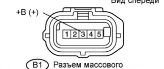
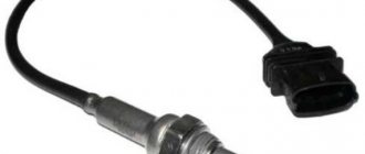
MAF pinout: 1) Yellow (closest to the windshield) - MAF signal input; 2)Gray-white—sensor supply voltage output; 3) Green - sensor grounding output; 4) Pink-black - to the main relay. Wire colors may change, but the pin layout remains the same. Wire colors may change, but the pin layout remains the same.
We turn on the ignition, but do not start the engine. We connect the multimeter with the red probe to the yellow mass flow sensor, and the black one to the green one (to ground). Thus, we measure the voltage between the specified terminals. The tester probes allow you to penetrate through the rubber seals of the connector, along the specified wires, without disturbing their insulation.
The use of needles and other additional connections is not recommended, because they introduce some error in measurements
. We take readings from the multimeter. The output voltage of the new sensor is 0.996…1.01 Volts. During operation, it gradually changes and, as a rule, increases. The greater the value of this voltage, the greater the wear of the mass air flow sensor.
Mass air flow sensor voltage: 1.01…1.02 - good condition of the sensor. 1.02...1.03 - not a bad condition. 1.03…1.04 - the life of the mass air flow sensor is coming to an end. 1.04...1.05 - a dying state, if there are no negative symptoms, then we continue to exploit it. 1.05...and higher - it’s time to replace the mass air flow sensor.
By the way, the same readings can be obtained without a tester, using the on-board computer (group of parameters “voltage from sensors”, Udmrv)
What is your MAF sensor? The first mass air flow sensor was a frequency sensor in the control system from GM. It was also used in “January” of the 4th series. Cars of this configuration did not last long and the frequency sensor was replaced by an analog model HFM-5 from Bosch under number 0280218004.
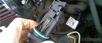
It is not interchangeable with GM; the connectors and mounting points are completely different. The German sensor is dismountable and consists of two parts - a housing and a measuring element. The latter is secured in the case with two screws with “secret” heads.
Bosch only sells assembled sensors in yellow cardboard packaging.
The third version of the mass air flow sensor is 0 280 218 037 or 037th, as determined by car enthusiasts by the last three digits in their designation. This is a further development of the 004 sensor from Bosch.
Such a sensor is used today on most VAZ cars, including Niva and Chevrolet Niva. Externally, 004 and 037 are almost indistinguishable; you need to navigate by their numbers.
Recently, additional markings have appeared on products: now there are numbers on both the body and the measuring element - they must match.
The main difference is inside the mass air flow sensor. The 037th sensor has a different design of the measuring element, with a characteristic cutout (when purchasing, it makes sense to remove the plug and look inside).
Then a new control system appeared - Bosch M7.9.7, which has its own, 116th mass air flow sensor. It is not interchangeable with the previous ones, although its body is the same.
To avoid confusion, a green circle was first applied to the body. There are numbers on both the body and the measuring element. The latter determines the purpose of this mass air flow sensor.
VAZ 2110 air sensor pinout diagram
- Yellow (closest to the windshield) - mass air flow sensor signal input;
- Gray-white—sensor supply voltage output;
- Green — sensor grounding output;
- Pink-black - to the main relay.
The wire colors may change, but the pin locations remain the same.
Let’s also add that the mass air flow sensor with endings 004, 037, 116 (for Bosch) and 00, 10, 20 (for Pekar) are different in calibration. You can only change it by flashing it.
Troubleshooting methods
If the diagnostics show that the mass air flow sensor is not working, then many car owners decide to immediately install a new sensor. In some cases, cleaning the regulator makes it possible to revive it.
How to clean the VAZ air flow sensor:
- First, using a Phillips-head screwdriver, you need to loosen the clamp securing the air intake pipe. Remove the corrugation and make sure that there are no traces of engine fluid or condensation inside. Also perform a visual inspection of the regulator surface.
- As practice shows, the cause of the problem is often the sensitive element, which usually breaks due to the accumulation of dirt inside the device. To prevent dust from accumulating, it is necessary to change the air filter from time to time.
- The controller itself is mounted on the corrugation using two bolts; they can be unscrewed using an open-end wrench. If you need to remove and replace the regulator, you can do so at this stage.
- From the front you can see the entrance on which the sealing rubber is mounted. Its purpose is to protect the system from the suction of dirty air flow coming from outside and not passing through the filter. If there is no sealing rubber, then most likely it could get caught through the filter element. Ultimately, the device's inlet mesh may become dirty. To restore functionality, you can try to clean it; for this, improvised means are used. For example, in practice, the mesh can be effectively cleaned with a toothbrush or toothpick. Alternatively, you can use WD-40 or a special cleaner for cleaning.
- After cleaning is completed, a rubber seal must be installed in place. When all work is completed, the regulator is put in place, all components are assembled in the reverse order.
1. Turn off the power and remove the device.
2. Clean the sensor and replace it.
Connecting the MAF air sensor VAZ 2112
If the mass air flow sensor is operational, then when the engine is running at 900 rpm, the volume of air used will be at least 10 kg per hour. When the speed increases to 2 thousand, this figure will increase to approximately 20 kg. If the volume of air at such speeds drops, the dynamics of the vehicle will also decrease, and accordingly, this will lead to a decrease in gasoline consumption.
If these indicators increase, this will also contribute to an increase in fuel volume. Deviations of the parameter by 2-3 kg should not be allowed, since in this case the operation of the power unit may be incorrect.
Basic faults
There is practically nothing to break in a film sensor, so they are considered “eternal”. The spiral of filament air flow sensors is less reliable, however, these electronic devices cannot be repaired in principle, with the exception of cleaning and replacement. The following symptoms will help determine the malfunction of this particular sensor:
- spontaneous decrease in engine power;
- decreased acceleration dynamics;
- engine not ;
- increase in fuel consumption unjustified by driving style;
- illuminated Check errors;
- change in XX speed in any direction, appearance of jerks;
- The car stalls when changing gears.
When diagnosing a low signal level, the following options are possible:
- the plug fell off;
- the power supply is broken;
- oxidation or loss of mass;
- signal wire break.
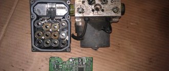
Rice. 10 Mechanical damage to the VU meter
Since the electrical device is not repairable, but has a simple design, diagnostics can be performed on your own according to the principle of increasing its complexity.
Connection diagram for air flow sensor 2114
A common cause of incorrect operation of the mass air flow sensor is the failure of electronic components, which increases the sensor’s response time to changes in air flow. A working sensor monitors changes at a speed of 0.5 ms, and if it breaks down, the response time increases by 20-30 times. The defect is detected only by recording the operation graph with an oscilloscope. Such a sensor cannot be repaired; it must be replaced with a new one.
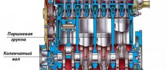
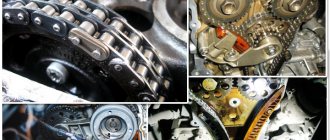
Design of the mass air flow sensor
Car enthusiasts call the mass air flow sensor a flow meter; in specialized literature it is designated as a volume meter. What is actually measured inside this electronic device is not the volume of air passing through it, but its mass per unit of time, moreover, compressed.
Since Ohm's law is familiar to every school graduate, the design of the mass air flow sensor is understandable to 100% of car enthusiasts:
- the device is analogous to an anemometer that measures flow speed;
- inside a tubular housing with an air deflector and a mesh metal screen at the inlet, the sensor itself is inserted perpendicular to the flow with a connector extending outward;
- Apply a current of 500 - 1200 µA to the thread or film inside the sensor, remove the voltage value 0 - 1 V in reverse flow or 1 - 5 V in normal mode;
- when current passes, the element heats up, its resistance increases (500 - 700 Ohms), and the voltage changes accordingly;
- The air flow cools the wire, the resistance decreases, and the voltage increases.
Rice. 4 Design of filament air flow sensor
The mass air flow sensor is connected according to the diagram below:
- green – to ground;
- white-gray – output voltage;
- yellow – input signal;
- dark – output signal.
Rice. 5 DMRV connection diagram
The film MAF has a built-in platinum resistor on a ceramic plate. In a filament sensor, the resistance is made of an alloy of iridium and platinum. The first VAZ models were equipped with sensors that controlled the flow rate based on the frequency of the output signal. Currently, domestic and foreign cars have mass flow sensors that determine fuel consumption based on voltage.
Rice. 6 Film mass air flow sensor
To increase functionality, the operating sensor uses two temperature-dependent elements. Since the difference in air temperature can introduce an error into the device readings, the second thread element compensates for it by measuring the temperature of the environment. Common to all devices is the presence of an adjusting screw, which is used to adjust the CO with your own hands. The designs of different manufacturers differ in the following details:
- thread thickness – 0.07 – 1 mm;
- method of fastening the thermally dependent element - laser welding, hooking with a loop on an elastic suspension;
- thread geometry – V-shaped or U-shaped;
- The design of the stand is square, eliminating errors when rotating the element around its axis.
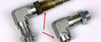
Rice. 7 German sensor and Russian analogue
In addition to these differences, factors to consider:
- thread devices began to be produced by Bosch and General Motors, then interchangeable analogues appeared from the APZ and JSCB Impuls plants;
- introduced a film-based air flow sensor from Siemens, which was copied by the Kaluga Research and Production Enterprise AVTEL;
- the thread is heated to 140 - 170 degrees, the film to 100 degrees;
- the accuracy of measuring film modifications is lower - 4%, for thread modifications is higher - 1%;
- The devices are interchangeable with each other, but only together with a bundle of wires, since the pinout of the wires does not match.
Rice. 8 Sensor connector
Currently, thread sensors are discontinued in Europe for a number of reasons:
- low level of manufacturability of thread production;
- the presence of corrective lambda probes;
- automatic calibration of films in blowing units.
In other words, manufacturers sacrificed speed and high accuracy for the sake of significantly reducing the cost of film mass air flow sensors.
Attention: For film sensors, the connection diagram to the MIKAS-7.1 controller, version 241.3763-31, is adopted. Filament air flow sensors MIKAS-5.4 and MIKAS-7.1 (version 241.3763-01) are used.
There is a domestically produced mass air flow sensor M with protection against overvoltage, short circuit and conducted interference.
Rice. 9 Modification of mass air flow sensor M
By default, thread sensors are based on the principle of self-cleaning of a temperature-dependent element. After stopping the engine, the ECU independently supplies current to the filament to warm it up to 1000 degrees for 1 second. The adhering dirt burns out completely.
Replacing the sensor - instructions
Using a screwdriver, unscrew the clamp of the air intake corrugation at the sensor outlet, pull it off and carefully inspect the internal surfaces of the sensor itself and the corrugation. These surfaces must be dry and clean; traces of condensation and oil are unacceptable. If the air filter is changed rarely, then dirt getting on the sensitive element of the sensor is the most common cause of its breakdown in VAZ cars.
There may be oil in the mass air flow sensor as a result of an increased oil level in the engine crankcase, or the oil sump of the crankcase ventilation system is clogged.
Next, unscrew the 2 screws of the sensor with a 10mm wrench and remove it from the air filter housing. There should be a rubber sealing ring on its front part (at the entrance edge). It prevents unfiltered air from being sucked into the intake tract through the sensor.
If the ring is out of place and stuck somewhere in the air filter housing, then there will be a thin layer of dust on the inlet mesh of the sensor itself. This is the second reason that destroys the mass air flow sensor ahead of time.
Correct assembly should take place in the following sequence: put a sealing rubber band on the sensor, check the sealing skirt, then insert everything together into the filter housing.
This concludes the visual check of the mass air flow sensor at home. You can check its operation 100% only with the help of special equipment in a car service center. For example, using a technique for assessing the oscillogram when the throttle is sharply opened to the cutoff mode (a motor tester is needed), or assessing the oscillogram when the ignition is turned on.
Resuscitation of a damaged air flow sensor is successful in no more than 5% of cases. In extreme cases, you can rinse with ethereal liquid to clean matrices and optics. It will evaporate without a trace. After making sure that there is no more dust or debris in the device, you can dry it thoroughly and put it back in place. Sometimes after such a simple procedure the device will work.
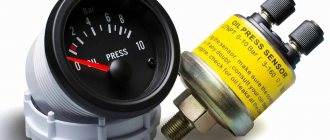
On most foreign cars, a mass air flow sensor was installed until 2000; subsequent generations of models began to be equipped with a pressure controller. Replacing a non-working sensor is simple and can be done on your own without any problems, you just need to buy a mass air flow sensor that matches the ECU firmware version. Its price is around 3,000 rubles, depending on the manufacturer.
How to check the serviceability of the mass air flow sensor
First of all, you need to regularly carry out computer diagnostics of your car, even in a garage, using basic car scanners. Any version of the Gazelle car is equipped with an OBD-II port, with which you can obtain detailed information about the operation of the engine’s electronic systems.
The initial parameters of the air flow sensor (we first select the model and type of engine on your car) are programmed into the diagnostic program. So a deviation from the norm will be recorded, and advanced programs will also suggest the probable cause of the breakdown.
However, there is a more primitive method that you can use if you don’t have a diagnostic scanner at hand. Every car enthusiast has a digital multimeter in their garage. The main thing is that its error is low: the voltage readings at the information contact of the mass air flow sensor vary within hundredths of a volt, and it is precisely this minimum range of values that the ECU is designed for.
The illustration shows the pinout of a sensor from Siemens, or its Russian analogues Avtel and Elkar.
- First of all, we check the integrity of the wiring harness and cable contact group. To do this (having first disconnected the negative terminal of the battery), disconnect the connector and connect the battery back. Turn on the ignition without turning the starter. There should be 12 volts on pin #2. Not 13.5, as on the battery, but precisely 12, after the voltage regulator. At pin No. 4 the sensor is supplied with 5 volts.
- Then we connect the connector back (remembering to temporarily disconnect the battery ground). We check the most important sensor signal: thermistor compensation voltage. With the ignition on, this value should be in the range of 0.99 - 1.02 volts. 1.03 - 1.05 volts are allowed, but such a mass air flow sensor will not last long. Any other value, even with a tolerance of 0.01 volts from the nominal value, indicates a breakdown.
Mass air flow sensor table. VAZ DMRV engines. Last three digits
But to implement them, it is necessary that the sensors informing the controller do not deceive it - only under this condition do the processes in the cylinders proceed normally, the engine develops sufficient power without consuming excess fuel and without causing much harm to the environment. One of these sensors measures the amount of air entering the cylinders and generates a corresponding signal to the controller. This can be an absolute pressure sensor (MAP sensor) or a mass air flow sensor (MAF). We see the latter on many cars, including VAZ ones.
The first was the frequency mass air flow sensor of the GM control system. It was also used in the domestic analogue “January” of the 4th series (photo 1). Cars of this configuration did not last long on the assembly line - the frequency sensor was replaced by an analog model HFM-5 from Bosch - its number is 0280218004 (photo 2). It is not interchangeable with GM - the connectors and mounting points are different. The German sensor is dismountable, consisting of two parts - a housing and a measuring element.
The latter is secured in the case with two screws with “secret” heads. True, nowadays you can buy the necessary tools in auto parts stores. The measuring element is a compact thing, but it is expensive - in Moscow from 1300 rubles. and higher. Having removed this part from a new car, in exchange, of course, they will put a dummy, and everything that follows is the “personal grief” of the car buyer. The market is full of such “mass air flow sensors without a housing”... It is unwise to buy a measuring element without a housing: it is very possible that it is faulty or the wrong model. Bosch only sells assembled sensors in traditional yellow cardboard packaging. Let us remind you that the store may not accept a return air flow sensor purchased from the “wrong system” if the motorist does not provide a certificate from the service, and it is often difficult to obtain one. An unnecessary expensive unit will remain as a keepsake.
The third version of the mass air flow sensor is 037. (Here we are talking about the last three digits in the designation.) This is a further development of the 004th sensor from Bosch. Such a sensor is used today on most VAZ cars traveling on the roads, including Niva and Chevrolet Niva. Externally, 004 and 037 are almost indistinguishable - just look at the number (photo 3). Recently, additional markings have appeared on products: now there are numbers on both the body and the measuring element - they must match. The main difference is inside the mass air flow sensor. In photo 4 on the right is the 037th sensor. It has a different design of the measuring element, with a characteristic cutout (when purchasing, it makes sense to remove the plug and look inside).
VAZ 2114 signs of flow meter malfunction
In addition to the indicator light on the Check Engine, there are symptoms that even an inexperienced driver will notice:
- Unstable engine operation at idle speed: the malfunction manifests itself most clearly when the engine is not warmed up. After starting, the revs fluctuate, and when the accelerator pedal is pressed sharply, the engine stalls.
- With a sharp release of gas, the speed does not decrease, but remains at around 2-3 thousand for some time.
- Even with a warm engine, there is a noticeable decrease in power. When fully loaded, a lower gear is required; the car does not pull uphill and accelerates slowly on the highway.
DMRV Siemens vdo 5WK97014 from VAZ 2104-2107 to VAZ 2110-2112 — Lada 2112, 1.6 l., 2006 on DRIVE2
I don’t know how to paint it beautifully, and I’m too lazy))) relevant for January, Siemens is notable for its price of 1900-2300 rubles and long service life, and there is no need to be tricky with attaching the air filter to the housing (in the classics there is a housing 2112))) as when installing a DMRV from gas. I chose the MAF from the Continental company. I had to smoke classic forums for a very long time))) I’ll write it down in parts (a link to the next part where the calibration implementation will be implemented and links to ready-made files will be at the end)
for installation in the software, you need to change the MAF calibrations in the native firmware (details will be in the next part) and to re-cross the wiring, you definitely need a Siemens MAF connector. Pinout: Bosch1 (DTV) 2 (+12V) 3 (ground) 4 (+5V from the ECU)
Siemens classic1-(+12v)2-(+5v from ECU)3-(signal)4-(DTV)5-(ground)
If the DMRV does not have DTV (4 wires go to the Bosch connector), then we connect according to the same scheme, ignoring the points with DTV.
The adapter is still rough. Later I’ll fill it with a heat gun or I’ll make it directly without an adapter. I soldered the adapter (from a dead MAF, grinding it down to the contacts), because I wasn’t sure that my topic would work. You can do without it: we pull out the wires from the Siemens connector (there are connectors with a double-sided clamp, you need to clamp it on both sides) and having pulled out the wires from the original plug (it’s easier to pull it out. The clamp is on one side), we stick it into the Siemens connector, observing the pinout. They fit like family.
ADDENDUM: it is very difficult to pull out the contacts from the original plug in the wiring. There is a lock on both sides)))
Issue price: 2,300 ₽