On VAZ-2109 vehicles with a carburetor fuel injection system, an exclusively non-contact ignition system was installed. It is much more reliable than contact, as it has a number of advantages. And the most important thing is the absence of friction between the active elements of the system. All work is done by semiconductor elements. The result is a long service life of the ignition system and stable operation under any conditions. And the most important thing is that you do not need to frequently adjust the ignition. The Hall sensor on the VAZ-2109 does not need constant monitoring; it is enough to install it correctly once.
Hall sensor VAZ 2109 - replacement without the help of specialists
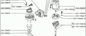
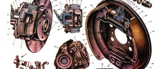
VAZ 2109 cars equipped with carburetor engines have a contactless ignition system with a Hall sensor. The main task of the VAZ 2109 Hall sensor is to supply control pulses to the switch, which converts the received pulses and directs them to the primary winding of the ignition coil. This microelectronic sensor is located in the housing of the ignition distributor sensor under the dust shield. Depending on the type of distributor, it is secured to the base plate using 2 screws or rivets. The operation of replacing the Hall sensor of a VAZ 2109 is not difficult. The replacement can be done within half an hour by any car enthusiast without the help of specialists.
Sensor check
It is not always the case that if the Hall sensor malfunctions, the car’s power unit does not start. There may be problems with ignition, such as interruptions in engine operation in any mode, absent or unstable idling, as well as loss of power. There are two ways to check the Hall sensor. The first is suitable for those who do not have special knowledge in the field of auto electrics and electronics.
With this method, you need to purchase a new and known-good sensor from an auto parts store and install it correctly in place of the old one. If the engine starts after this operation, then the problem is solved. If not, then the problem is in the resistor, switch, coil, ignition switch, wires, spark plugs or other parts of the distributor.
https://youtube.com/watch?v=DiWtCGGKN6s
The second method of checking the VAZ 2109 Hall sensor requires special knowledge in electrical engineering. In addition, to carry out self-diagnosis, you must prepare the following instruments and devices:
- a voltmeter or multimeter with a measurement limit of at least 15 V and an internal resistance of at least 100 kOhm;
- 3-pin block from the distributor with low-voltage wires;
- resistor with a resistance of 2 ohms.
The check must be carried out as follows.
- First you need to remove the distributor from the car.
- Then you need to connect a block with wires, a resistor and a voltmeter to the connector of the low-voltage wires according to a certain circuit.
- After this, you need to apply voltage from the battery (9-14 V) to the positive contact and slowly turn the distributor shaft.
- During this operation, you need to record the minimum and maximum voltmeter readings.
Normally, the minimum voltage should be less than or equal to 0.4 V, and the maximum should not differ from the voltage supplied from the battery by more than 3 V. If, when turning the distributor shaft, there is no sharp voltage jump or the minimum and maximum values differ from the norm , this means that the sensor is broken and should be replaced.
Replacing the device
Replacing the Hall sensor
In order to replace the Hall sensor, you first need to remove the distributor from the drive of the auxiliary units. The dismantling algorithm is as follows.
- First of all, you need to disconnect the terminals from the battery.
- Then you need to remove the armored wire from the cover of the breaker-distributor and unhook the hose from the vacuum corrector.
- Then you need to remove the throttle cable from the holder so that it does not interfere, unscrew the nut securing the bracket on which the wires are held, remove the bracket from the stud and move it to the side.
- Next, you need to scratch with a screwdriver or draw a straight line with a marker, passing from the distributor body to the drive housing of the auxiliary units. This mark will allow you to maintain the same ignition timing during installation of the distributor.
- After this, you need to unhook the block with wiring from the breaker-distributor.
- Then you need to remove the dirt plug from the clutch housing hatch and use a screwdriver to turn the flywheel until the piston of the first cylinder is in the top position.
- Now you need to unscrew the 2 remaining nuts and remove the distributor.
After dismantling the unit, you can begin replacing the sensor; to do this, you need to follow a sequence of actions.
- Unscrew the screws and remove the distributor cover.
- Pull the slider up and remove it, then remove the dust shield.
- Remove the low-voltage wire connector by unscrewing the screw.
- Unscrew the screws securing the support plate and remove the ring from its pin.
- Unscrew the screws of the vacuum corrector, remove its rod from the plate pin and remove it from the body.
- Lift the plate with a screwdriver and also pull it out of the case.
- Unscrew the screws securing the sensor and replace it with a new one.
If the sensor is attached to the plate with rivets, then they need to be replaced as an assembly. Installation of the device should be carried out in reverse order. Before installing the distributor, you need to turn the outer contact of the slider to the terminal of the first cylinder.
Where is the sensor located?
On VAZ cars of the 2109 family, the device in question is responsible for connecting and opening the contact group. The signal received by the sensor is converted into electrical form. Through the switch, it goes to the ignition coil, where a spark is already generated.
In carburetor cars, the device is installed on the ignition distributor under the protective shield. The sensor is fixed to a special plate using two bolts. Rivets are sometimes used. It all depends on the type of distributor.
How to remove the sensor?
In order to perform the replacement, you need a “10” key and a screwdriver. This is quite enough, but it is still recommended to have pliers with you. So, you need to remove the distributor and disassemble it:
Disconnect the ground wire from the battery. Disconnect all the armor wires and the vacuum corrector tube from the distributor. If in doubt, mark the location of the armor wires so as not to be confused. Unscrew the three nuts that secure the distributor housing to the engine head
Pay attention to the position in which the body was standing. Disconnect the wiring block and remove the distributor housing. Now you need to disassemble it; to do this, remove the cover by unscrewing two bolts
Next, remove the slider and underneath it is the Hall sensor
Now you need to disassemble it; to do this, remove the cover by unscrewing two bolts. Next, remove the slider and underneath it is the Hall sensor.
How to install a new one?
When replacing the Hall sensor on a VAZ-2109, you must follow a strict procedure. Distortions are not allowed, as this will lead to system inoperability. All wires are carefully laid inside the distributor housing so that moving elements do not damage them.
Remove the old sensor and put a new one in its place. Assemble the distributor in the reverse order - the dust cover should fit into the groove, then install the slider. By the way, it’s worth checking - the resistance is about 5 kOhm, there should be no carbon deposits or melting. If there is damage, the element must be replaced. If replacing the sensor does not help, you need to look for a problem in the injection system or switch or coil.
How to replace the hall sensor on a VAZ 2108-VAZ 21099?
Note! The sensor is not difficult to remove, but when installing it, be careful with it, especially with its wiring, because there were cases due to an incorrectly installed sensor, the curtains that rotate in a circle and which are in the distributor broke off all its wiring. You can check it out in one of the videos at the end of the article and by the way, don’t be especially afraid to change this sensor, there’s nothing complicated there, you just need to remember some little things and be sure to remember how to assemble the distributor in reverse order, if you succeed, then you’ll replace the sensor without difficulty on your distributor!
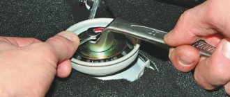
Disassembly: 1) First, remove the distributor from the car (For information on how to remove it from the nine, read the article: “Replacing the ignition distributor on a VAZ”), when it is removed, you can proceed to disassembly, first unscrew the two side screws that secure the cover to ignition distributor and then remove it, when you have it in your hands, remove the slider that stood behind it (see small photo), it can be removed using your hand, that is, just pull it and thereby it will be removed from the shaft and by the way, inspect there should be no cracks, burn marks, or corrosion on the slider, otherwise it must be replaced.
2) Now remove the dust shield with a screwdriver (by prying it up) as shown in the photo, inspect it too, it can crack and therefore, through cracks are formed due to which dirt will sooner or later get into the inside of the distributor itself, which is very will reflect badly on him.
3) Then unscrew the screw with a Phillips screwdriver, thanks to which the connector to which the block of wires is connected holds and does not fall (see large photo below), after unscrewing, remove the connector from the distributor body and then open the claws on the holder that secures the sensor wire to the distributor body hall (see small photo) and remove the sensor wire.
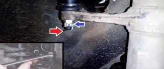
4) Next, carefully use a screwdriver to pry up the retaining ring that holds the vacuum corrector rod on the pin (You can see the rod located on the pin in the small photo below, it is indicated by a red arrow) and then remove this rod from this pin, then unscrew the two screws that secure the vacuum corrector itself and remove it (see the main photo, it shows the removal of one screw securing the vacuum corrector).
5) And finally, unscrew the two screws indicated by the arrows and, lifting the support plate (see small photo), remove it from the voltage regulator and, by the way, this very sensor that you need will be on it.
Note! When the support plate is removed, unscrew two more screws securing the sensor and disconnect it from this plate (On some distributors the sensor may still be attached with rivets, if this is the case with you, then replace the sensor assembly with the plate with a new one), replace it with a new one and be sure to install it correctly and as it should be (remember how it was previously, so install it, if you don’t remember, then open the videos at the end and review them, they showed in detail how to remove this sensor, how to check it and how to install it back)!
Assembly: Everything is assembled in the reverse order, during assembly it is recommended to lubricate all the bushings and the shaft on which the runner is installed a little with engine oil and during assembly, make sure that there are no cracks or signs of heavy wear on the parts, otherwise replace them for new ones.
Additional video: You can clearly see an example of an incorrectly installed hall sensor in the video below; in addition, it also describes how you can check its functionality.
It will be useful: How to remove the starter from a Chevrolet Niva
Note! In addition to the top video, there is another one, which shows the whole process, as they say, “from and to” of disassembling and assembling the ignition distributor, also known as the distributor, be sure to study and review it in order to carry out the work correctly without jambs!
Checking Hall sensor
Today, there are several most common methods for checking households. We list the most popular and simple ones for home use:
- creating an imitation of the presence of a controller;
- checking with a multimeter, tester;
- checking by replacing with a known working sensor;
- to resistance.
- Checking the Hall sensor with an oscilloscope
Let's take a closer look at each of the methods.
Creating a simulated household
This method is the simplest and is suitable if power is supplied to the ignition, but a spark does not appear. To do this, you need to remove the three-pin block from the distributor. Then the ignition is turned on and the second and third contacts – “minus” and signal – are closed with a piece of conductor. If during such manipulations there is a spark on the central wire of the ignition coil, then it is necessary to replace the sensor, this one has failed. It is worth noting that in order to detect the presence of a spark, the high-voltage wire must be fixed near the ground.
Checking serviceability with a multimeter
Connection diagram This is the simplest and most common diagnostic method for home use. To do this, the multimeter switch must be switched to the voltmeter position, voltage measurement. Then, using probes, measure the voltage at the sensor output. On a working sensor, the voltage reading should be in the range of 0.4 – 11 V.
Replacement with a working one
The method is simple and does not require car owners to have knowledge in the field of electrical engineering. You can buy a new one in a store or borrow it from friends, the main thing is that the sensors are identical. If the machine works normally and the signs of malfunction disappear, it means your sensor has become unusable.
For the presence of resistance
Scheme Also refers to a very common method, but a little more complicated. You will need to build a simple device. For it you need to take a 1 kOhm resistor, an LED and some flexible wire. A wire of a convenient length for operation is soldered to one leg of the LED, a resistor to the second, and the same piece of wire to it.
Then the distributor cap is disconnected, the distributor and the plug box are disconnected. The next step is to check the electrical circuit. To do this, connect the multimeter probes to terminals 1 and 3 and turn the ignition key. If everything works normally, then the multimeter display should show a value of 10 - 12 volts.
Then the previously assembled device is connected to the same terminals. If the polarity is correct, the LED will light up. If it does not light up, you need to rearrange the wires on the contacts.
Further actions:
- leave the wire of the first terminal in place;
- transfer the wire of the third terminal to the second;
- Use the starter to turn the camshaft.
When turning the shaft, the LED should flash. If this does not happen, then the Hall sensor is faulty. It is worth noting that checking sensors is the same on any car, both domestic and foreign. The difference may only lie in the location of the parts under the hood.
Checking the DC with an oscilloscope
You can diagnose the Hall sensor using an oscilloscope; we take a voltage oscillogram and if there are interruptions or no pulses at all, we reject the DC. But this method requires specialized equipment that is not advisable to buy for home use.
Checking the Hall sensor on cars such as VAZ 2106, 2107, 2109, as well as Passat b3 and Audi 80 is absolutely the same.
Another diagnostic method
Before checking the Hall sensor on the VAZ-2109, you will need to make preparations.
But at the same time you will certainly determine the integrity of the device. Execution procedure:
However, if the operation of the sensor is unstable, this method may not help - try installing a known good one.
How to check the hall sensor on a VAZ 2109 carburetor
Well, in general, I’m sitting here now, and I feel that anger is growing inside me towards those people who, apparently, do not understand how the contactless ignition system works and are trying to squeeze something out of themselves, insert their two cents, so to speak, into conversation. If you are one of them, then read carefully. Such experts claim that if there is no spark at the center (high-voltage wire from the coil to the distributor, that is, the distributor), then the hall sensor has nothing to do with it.
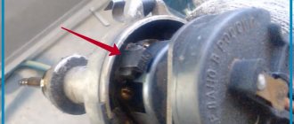
Let me ask you, why do you think a Hall sensor is needed? Is it possible to throw a spark through the cylinders? For this purpose there is a slider and a distributor cover. The Hall sensor is the initial stage of spark formation (!). Now I will try to explain clearly with an example. On the distributor roller there is a screen with slots as seen in photos 1 and 2. When this roller (and the screen, respectively) rotates, these slots (indicated with a screwdriver in the second photo) pass through the gap of the Hall sensor (indicated with a screwdriver in photo 3), resulting in the formation an impulse that then goes to the switch, then from the switch goes an impulse to the ignition coil, and then a spark comes from the coil! If the Hall sensor does not send a pulse, the switch will fail.
There is a fairly simple method that allows you to accurately verify that the Hall sensor is faulty: Turn on the ignition (do not turn the starter), remove the mother (chip) from the Hall sensor (photo 4), take a screwdriver or something else and short the middle wire to ground ( in my case there are only two wires, no one knows where the third one went
Functions and location
On carburetor VAZ 2109, the Hall sensor (HL) is responsible for opening and closing the contact group. When the screen with windows is rotated, a signal is sent to the device, which transforms into an electrical one. Through the switch, the signal goes to the ignition coil, and there it turns into an electric charge - a spark.
The DH is located at number nine on the ignition distributor. You need to look for the device under the dust shield. The sensor is secured to the base plate using rivets or a pair of screws. This already depends on the type of distributor used.
On injection VAZ 2109 there is no Hall sensor. Its functions are performed by the crankshaft position sensor.
Signs of breakdown
If the DC fails, the car itself will notify you that there is a fault. To determine problems with the diesel engine, there are certain signs coming from the engine:
- You simply cannot start the engine;
- There are interruptions in the operation of the power unit - the smooth running becomes not so smooth, jerks appear;
- Idle speed is broken or completely absent;
- The engine may suddenly turn off or stall;
- Motor power is noticeably lost.
Before you run to the engine compartment and change the Hall sensor, first you need to make sure that it is the cause of all the troubles with the engine. Still, the signs are indirect, and they can be caused by a malfunction of other elements of your car.
Installation location
Checking status
There are several main methods that are used today to check the current state of the Hall sensor. Let's get to know each of them in more detail, and you decide for yourself which one you will use the next time you check the DH on your VAZ 2109.
Verification method
Your actions
Replacing an old device with a new one
This is the simplest method, which will require you to have a spare Hall sensor on hand, of which you are confident that it will work. Simply remove the old sensor, insert the new one in its place and try to start the car. If everything works, you have found the reason. If not, you will have to look for the source of the problems in other systems.
Checking the output voltage
For this method, you will need a tester connected to the output of the device. If the Hall sensor is working properly, the tester will show values in the range of 0.4-11 Volts. If the data does not meet the established standards, the household will have to be replaced
Simulation of device operation
A popular method in which you deceive your own car by simulating the operation of the Hall sensor. You need to remove the plug block, turn on the ignition and connect outputs 3 and 6 together. If a spark starts to jump, you can be sure that your sensor has failed.
Checking without additional devices
Here you don't need a tester or voltmeter. First, connect the lead from the coil to the spark plug, and connect the thread of the spark plug to ground. Remove the carriage with the sensor and attach the connector. Now you can turn on the ignition. Using a screwdriver, move the tool near the device - the Hall sensor. If a spark appears on the spark plug, this indicates the serviceability of the DH. If not, the conclusion is obvious.
Device check
If you discover that the DC is faulty, you should definitely replace the device. We do not recommend delaying this event.
There is nothing particularly difficult about replacing the DH on a domestic nine. Therefore, even a novice driver can take on the job with his own hands.
- Disconnect the negative terminal from the battery.
- Disconnect the armored wires from the distributor, disconnect the hose from the vacuum corrector.
- Next, remove the gas cable and put it aside for now so as not to interfere with the process.
- Unscrew the bracket fasteners that hold the wires. Remove the bracket from the stud and move it aside. Otherwise he will disturb you.
- Be sure to draw a straight line on the auxiliary drive housing and distributor. This location will allow you to avoid disturbing the ignition timing during reassembly.
- Disconnect the power supply with wires.
- Remove the plugs from the clutch housing and turn the flywheel with a screwdriver so as to set the piston of the first cylinder to the top dead center position.
- To remove the distributor, you need to unscrew two more mounting nuts holding the device.
- Remove the cover from the distributor, remove the slider and pull it up. Only a little.
- Remove the dust cover.
- Now unscrew the mounting bolt to remove the plug.
- We also need to unscrew the bolts that hold the plate of our desired sensor.
- Remove the vacuum corrector mounting bolts, remove the retaining rings, corrector and rod.
- To get the wires out, you will need to release the clamp there.
- Remove the mounting plate and unscrew the mounting bolts, which will allow you to finally remove the failed Hall sensor.
- It is now necessary to install a new sensor and assemble the unit, proceeding in the reverse order.
It is important not to change the ignition settings
Don’t forget, after completing the work, be sure to check whether your carburetor VAZ 2109 is working correctly, and whether you have violated the ignition timing.
The main difficulty in the process of replacing the diesel engine is the need to get to the sensor, as well as the existing risks of disrupting the proper operation of the carburetor. But if you act carefully and strictly according to the instructions, problems can be avoided.
Hall sensor on the VAZ 2107: its purpose, types of breakdowns and replacement
When the Hall sensor on a VAZ 2107 breaks down, this makes it impossible to continue driving. The Hall sensor belongs to the category of key parts of a contactless ignition system, and if this part begins to fail, the switch will stop sending impulses to produce a spark. To troubleshoot the problem, you need to understand in detail the purpose and operation of the device.
Why is a Hall sensor needed and how does it work?
The device of the contactless ignition system of the VAZ 2107 car has such an element called a Hall sensor. Its fundamental purpose is the ability to detect the angle of the crankshaft and camshaft of the power unit. The Hall sensor is not installed on injection models of sevens, it is installed only on carburetor ones.
According to the value of this device, voltage pulses are supplied to the spark plugs. The functioning of this element is based on increasing the voltage in the cross-section of a wire placed in a magnetic field. The element is connected by three terminals, two of which provide power supply (plus and minus), and the third contact is intended directly for supplying a signal. The device received this name due to a special effect that was identified by scientist Hall. In the distributor on the shaft there is a plate that is part of the control of the device controller.
When the motor operates, the metal in the slots alternately changes, and the magnet, which is located inside the controller, begins to be excited by oscillations of the magnetic field. In this case, the controller generates voltage pulses issued by the switch and supplied to the coil. The coil, in turn, raises the voltage to a high value and transports it alternately through armored wires to the spark plugs
Knowing the operating features, you need to deal with the malfunctions, but before that it is important to note that the Hall sensor on the VAZ 2107 is located in the distributor under the cover. To replace it, you will need to disassemble the distributor
Basic sensor malfunctions
Any part on a car sooner or later begins to malfunction, and the Hall sensor is no exception, even though it has the simplest design. Its breakdown is detected by detecting the following defects:
- Inability to start the engine.
- Unstable and unstable operation of the motor.
- The occurrence of jerks.
- The engine begins to stall.
- The appearance of the detonation effect.
If the above symptoms appear, then there is no need to rush to change the Hall sensor, since similar phenomena can also occur due to other breakdowns of the ignition and fuel supply system. To verify that the device is faulty, you will need to perform a suitability test.
Check Features
The BSZ contactless ignition on the VAZ 2107 has a Hall sensor, the serviceability of which determines the normal operation of the internal combustion engine. If you suspect that it is faulty, then you need to check the Hall sensor. To do this, there are different ways on the basis of which one can draw a conclusion about the suitability of the element.
The following two methods are used to check an element:
- The simplest test method is to install a known-good element. If the signs of malfunctions immediately disappear, it means that the breakdown was detected correctly and successfully repaired. The disadvantage of this method is that you must first purchase a working element.
- Use a multimeter to check the voltage at the sensor output. The device switches on the voltage measurement mode, after which the value at the device output is measured. The value should be between 0.4 and 11 Volts, and if this is not the case, the element should be replaced.
- Simulation of device operation. The test diagram is as follows - the element terminal should be removed from the connector, and then turn on the ignition. Now we begin to simulate the operation of the Hall sensor, for which contacts 3 and 6 of the switch output are connected. If sparking occurs, the element must be replaced.
It is also important to check the serviceability of the terminal block to which the Hall element is connected. A multimeter set to voltage measurement mode is also used for this.
One probe of the device needs to be thrown to ground, and the second one needs to check the readings on the red and green wires. The value of the readings should be equal to the voltage value on the battery.
Troubleshooting
To determine a malfunction on a carburetor engine, you will need to know for sure that the device in question is the cause of all the problems. Accordingly, it is necessary to check the sensor.
This can be done in several ways:
- The most primitive method is to install a new element instead of the old device. If all symptoms disappear, then we can assume that the problem is solved. Otherwise, you need to look for a breakdown in other components of the ignition system.
- Using a tester, check the output voltage. If the device is working, the values will be in the range from 0.4 to 11 V.
- You can simulate the operation of the system. To do this, remove the block with three plugs, turn on the ignition, and close wires 3 and 6. The presence of a spark indicates that the device has failed.
Signs of breakdown
If the DC fails, the car itself will notify you that there is a fault. To determine problems with the diesel engine, there are certain signs coming from the engine:
- You simply cannot start the engine;
- There are interruptions in the operation of the power unit - the smooth running becomes not so smooth, jerks appear;
- Idle speed is broken or completely absent;
- The engine may suddenly turn off or stall;
- Motor power is noticeably lost.
Before you run to the engine compartment and change the Hall sensor, first you need to make sure that it is the cause of all the troubles with the engine. Still, the signs are indirect, and they can be caused by a malfunction of other elements of your car.
Installation location
Types and scope of application
Despite the variety of elements that use the Hall effect, they can be divided into two types:
- Analogue, using the principle of converting magnetic induction into voltage. That is, the polarity and voltage directly depend on the characteristics of the magnetic field. Currently, this type of devices is mainly used in measuring technology (for example, as current, vibration, rotation angle sensors).
Hall effect current sensors can measure both AC and DC current - Digital. Unlike the previous type, the sensor has only two stable positions, indicating the presence or absence of a magnetic field. That is, operation occurs when the intensity of the magnetic field has reached a certain value. It is this type of device that is used in automotive technology as a sensor for speed, phase, camshaft position, as well as crankshaft, etc.
It should be noted that the digital type includes the following subtypes:
- unipolar - triggering occurs at a certain field strength, and after it decreases, the sensor returns to its original state;
- bipolar - this type reacts to the polarity of the magnetic field, that is, one pole turns the device on, and the opposite pole turns it off.
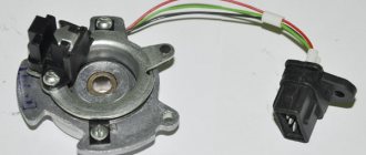
Appearance of a digital Hall sensor
As a rule, most sensors are a component with three pins, two of which are supplied with bi- or single-pole power, and the third is a signal one.