Print this article Font size 16
The ignition system of the VAZ 2109 consists of a number of devices whose task is to create an electrical discharge that ignites the air-fuel mixture in the engine. Among these devices there is a distributor.
Distributor and ignition distributor are synonyms. Remember this so that in the future there are no problems with misunderstanding of instructions for repairing the ignition system .
instructions and purpose
Let's first consider the general purpose, design and types of distributors:
- The distributor is part of the ignition system, and is designed to regulate, transmit and control the electrical signal to the distribution coil switch, igniting the spark along the spark plugs in the required accordance (in sequence with the ignition stroke)
- There are two types of ignition systems - non-contact and contact (of course, there are others, but they are not very common), accordingly, distributors are also used of two types
- friend They differ from each other only in design: the presence of contacts (in a contact system there is a breaker), a sensor distributor (in a contactless ignition sensor system there is a distributor)
- According to the main characteristics, both systems are almost identical
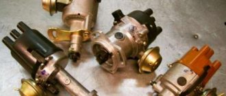
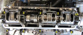
On VAZ-2109 cars, as well as 2108 models-2199, a distributor with a built-in Hall sensor, four spark, with built-in centrifugal (regulators and vacuum) ignition timing is standardly installed. You can see the main details in the photo above:
- 1 - sealing ring
- 2 - special
- 3 – coupling adjusting washers
- 4 - roller with a centrifugal regulator located on it
- 5 — support plate
- 6 – screen, protecting from dust
- 7 - the so-called “runner”
- 8 - Hall sensor itself
- 9 — lock washer
- 10 - thrust washer
- 11 — distributor, ignition housing
- 12 — vacuum corrector
Operating principle of the ignition system
We replace the VAZ 2114 heater radiator with our own hands, instructions and nuances.
The process of burning the mixture in the cylinder takes some time. If the mixture ignites while the piston is at TDC, then it will burn after the piston passes TDC, catching up with it, that is, during the expansion stroke of the combustion chamber and exhaust gases. This will create insufficient pressure on the piston, as a result of which efficiency will be noticeably reduced and fuel consumption will increase (ignition is delayed).
When the mixture is ignited long before the piston passes TDC, a significant part of the energy will be spent on overcoming the pressure by the piston during the process of explosive combustion of the mixture. In this case, detonation occurs (early ignition). In addition, if the VAZ ignition is set incorrectly, the engine will overheat due to the increased absorption by the cylinder walls of the heat released during combustion of the mixture.
That is why the optimal ignition timing is considered to be one at which the mixture ignites shortly before the piston passes TDC, so that the combustion of the mixture coincides as much as possible in time with the piston passing TDC. In this case, the VAZ ignition timing provides the best operating mode.
In order to control the ignition of the VAZ 2109, divisions are applied in the clutch housing hatch shaft, and a mark is installed on the flywheel. When the point on the flywheel coincides with the central mark in the hatch, the pistons in the first and fourth cylinders are set to top dead center (TDC).
The way to control the VAZ ignition installation “on the move” is as follows: moving at a speed of 40-50 km/h on a flat section of the road with fourth gear engaged, you need to press the gas pedal to the floor. If, while accelerating, a slight detonation is heard, which disappears almost immediately, the ignition is set correctly. The absence of detonation manifestations indicates late ignition. Excessive detonation is a sign of early ignition of the combustible mixture.
VAZ 2109 Oil in the distributor video - Self-repair of cars
DIY VAZ 2109 repair
A part called a “distributor” performs the function of ignition distribution and has a direct impact on the stability of the functioning of the automobile engine. The main task that this product is designed to solve is the regulation of spark formation depending on the load, number of revolutions and other engine operating parameters, and subsequent correct distribution the resulting spark on all cylinders.
Distributor - its design and purpose
The specified product is an element of the ignition system that solves a complex of problems:
- Adjustment of the signal level (electrical), its control, as well as subsequent transmission to the reel-to-reel switch;
- Distribution in the required sequence of the resulting spark to the spark plugs, which is set by the ignition strokes;
Today, 2 types of ignition systems are used in car designs: contact and non-contact. There are other technical solutions, but they are used on models, the number of which is negligible. The distributors installed in them differ in design very slightly and are almost identical in basic characteristics. Therefore, having realized that oil is flowing from under the distributor of the VAZ 2109, you can carry out work to eliminate the identified malfunction using the same methods.
How to make a replacement
Replacing oil seals in a VAZ 2109 engine is a relatively labor-intensive procedure that requires special skills and certain tools. It is advisable to carry it out in a garage or workshop. Allow enough time for work so as not to rush. Replacing oil seals in a VAZ 2109 engine requires care, precision, and attentiveness.
Prepare everything you need
Successful replacement of valve stem seals can be done with your own hands. But this will require more than just a simple set of keys. You will have to take care of preparing special devices. Before starting work, you must equip:
- tin (or soft metal) rod with a diameter of no more than 8 mm;
- desiccant;
- tweezers;
- hammer;
- set of keys, socket heads;
- pliers;
- collet (puller) for removing oil seals;
- flat screwdrivers;
- press-fit frame.
Distributor VAZ 2109
Replacing the camshaft oil seal on a VAZ 2109
In this article we will talk about the device, the main malfunctions and repair of the distributor (ignition distributor) for the VAZ 2109 car, we will consider the step-by-step replacement of the distributor oil seal and the device as a whole.
Trambler VAZ 2109 device
1 - sealing ring, 2 - coupling, 3 - adjusting washers, 4 - roller with centrifugal adjuster, 5 - support plate, 6 - dust shield, 7 - slider, 8 - Hall sensor, 9 - lock washer, 10 - thrust washer, 11 - housing, 12 - vacuum corrector.
The main reason for the failure of the VAZ distributor is wear of the oil seal and, in rare cases, the roller with the centrifugal regulator; to eliminate oil leakage into the Hall sensor, we recommend replacing the oil seal of the VAZ 2109 distributor.
Replacing the VAZ 2109 distributor oil seal
To replace the ignition distributor oil seal, you need to remove the distributor (to remove the distributor, you need to unscrew the two distributor cap screws, remove the distributor cover, disconnect the hose from the vacuum corrector, set the piston of the first cylinder to TDC, unscrew the three nuts securing the distributor, and then carefully remove it). Next, we disassemble the distributor:
Disassembly: Ignition distributor VAZ 2109
- Remove the slider by pulling it up.
- Remove the dust shield.
- Unscrew the screw securing the low voltage wire terminal.
- Remove the terminal from the distributor housing.
- Unclench the holder's claws with a screwdriver and remove the wire from the holder.
- Remove the two screws securing the Hall sensor support plate.
- Remove the retaining ring from the backing plate pin.
- Unscrew the two screws securing the vacuum corrector.
- Using a screwdriver, remove the vacuum corrector rod from the support plate pin.
- Remove the vacuum corrector.
- Using a screwdriver, lift up the support plate and remove it.
- Remove the retaining ring from the distributor shaft.
- Remove the thrust washer from the distributor shaft.
- Remove the snap ring holding the clutch mounting pin.
- Pry up the O-ring with a screwdriver and remove it.
- Drive out the coupling mounting pin using a suitable punch.
- Remove the distributor drive clutch and shims.
- Remove the roller with the centrifugal regulator.
- Using a screwdriver, remove the two weight springs from the struts.
- Remove the centrifugal governor driven plate from the screen.
- Remove the retaining rings securing the weights.
- Remove both weights from the axles.
- Unscrew the two mounting screws and remove the Hall sensor from the support plate.
- Remove the coal with the spring from the cover if it needs to be replaced.
Note: On some distributors, the Hall sensor is attached to the base plate using rivets. In this case, the Hall sensor of the VAZ 2109 is replaced as an assembly with the support plate.
By the way, touching on the sensor, many will be interested in knowing how to check the Hall sensor of a VAZ 2109? When the starter is turned on, if at least one spark jumps on the removed spark plug with the ignition wire connected, then the Hall sensor requires replacement, this is the simplest popular way to check, you can check it with a tester, but that’s another story and I’ll tell you about it in another article.
Assembly and installation of the VAZ 2109 distributor is carried out in the same sequence as disassembly. Also, when replacing the distributor oil seal, we recommend replacing the gasket under No. 1 in the figure, checking the condition of the cams and the slider, and if necessary, cleaning the contacts with sandpaper or a needle file. Next, install the ignition.
Dismantling
After dismantling the distributor, you can disassemble the device in order to repair its components, or completely replace the distributor with a new unit.
- De-energize the car by removing the negative from the battery;
- Disconnect the high-voltage components and the vacuum ignition corrector hose from the distributor;
- Remove the drive cable responsible for the throttle valves from the bracket. Next, the fastening nuts are unscrewed and the bracket is dismantled;
- Before removing the ignition distributor, apply a mark to the housing of the distributor and drive of auxiliary elements. This way you can simplify your task of setting the ignition timing for its precise setting. The mark is applied to the metal by scratching;
- Press the latch holding the block with the power wires and disconnect it from the distributor;
- Place the piston from the first cylinder to the top dead center position by moving the engine flywheel clockwise;
- Unscrew the remaining ignition distributor screws. The first fastener was removed when removing the damper cable sheath bracket;
- Remove your damaged distributor.
Disassembly and repair
Quite often, repair work with the distributor is associated with wear and the need to change the seals (coupling). To change the oil seal, as well as other failed components of the distributor, we bring to your attention the appropriate instructions, as well as video tips.
When planning repairs, it is advisable to purchase a special repair kit and a new distributor in advance. The repair will give results, but for a certain time. You'll have to replace it soon anyway.
- Remove the ignition distributor cap by releasing the locking clip.
- Remove the slider. It is wiped with a clean rag and checked for mechanical damage. If there are chips or cracks, the element must be replaced.
- The runner must fit tightly on the shaft, which is achieved due to the presence of a plate spring with a pressing action. If it stretches or breaks, replace it.
- There is a resistor in the slider housing. The normal reading of its resistance is 1 kOhm. By measuring the data with an ohmmeter, you can draw conclusions regarding the performance of the component.
- Remove the low voltage wiring terminal. To do this, unscrew the mounting screw from the housing.
- Remove the plastic screen that serves as dust protection.
- A power wire comes from the Hall sensor and is held by the holder's claws. Using a screwdriver, the claws are opened and the wire is removed. Next, you need to unscrew the pair of mounting screws securing the Hall sensor support plate.
- Remove the vacuum corrector. Just be sure to disconnect it from the support plate lever before doing this. To perform this operation, carefully remove the retaining ring from the pin.
- The next step is to remove the pair of screws that hold the corrector to the distributor body.
Disassembling the unit
- Lift the corrector lever slightly, which will allow you to remove it from the sensor plate pin and remove the corrector itself.
- These steps will allow you to easily remove the support plate by lifting it with a flat head screwdriver. Remove the element. The plate must be replaced if the bushings are worn out or there is mechanical damage to the unit.
- Unscrew the two fasteners to disconnect the plate and the Hall sensor.
- You need to remove the oil seal, that is, the coupling. It is located on the distributor shaft. The coupling is closed with a thrust washer. That, in turn, is fixed with a retaining ring. You first need to remove the ring, which will make it possible to remove the thrust washer.
- Remove the oil seal by knocking out the pin with a small-diameter borer. Determine the dimensions of the boletus during the repair process.
Checking for damage
- There are adjusting washers under the oil seal.
- Remove the roller along with the centrifugal regulator from the distributor body.
- Clean the housing using kerosene and a dry cloth. Make sure that there are no mechanical damage, chips or cracks on the case.
- Examine the condition of the bushings. The roller rotates on them, and with severe wear, the roller begins to become loose. Also, the device is replaced along with the bushings if there are signs of wear, defects, or damage.
- To disassemble and replace damaged elements of the centrifugal regulator, you first need to remove the weight springs using a screwdriver.
- If the springs are intact and undamaged, not deformed, make notes on their seats. If you mix them up during assembly, problems may arise.
- Remove the driven plate along with the screen from the shaft.
- Make sure how effectively the weights move along their axes. Movements should be free, without any jamming. If there are problems, the weights are changed.
- It is a mistake to check the movement of loads without first removing and cleaning them.
As you disassemble the distributor, you will be able to identify damaged components and replace them with new ones using a repair kit. If the damage is serious, it is better to replace the entire ignition distributor.
The distributor is an important and sometimes capricious element. But replacing it and repairing it shouldn’t cause any problems.
Do-it-yourself distributor replacement Repair VAZ 2109-2108
Before you begin removing the distributor (ignition distributor) on a VAZ 2109-2108, you must disconnect the negative terminal from the battery
This procedure is not as difficult to perform on your own as it might seem, but there are very important points that are worth paying attention to. This will be discussed in detail during the description of the procedure.
To perform this repair you will need the following tools:
- 10 open-end wrench or socket wrench
- Socket head and ratchet handle
- Phillips blade screwdriver
The procedure for removing and installing the distributor on a VAZ 2109-2108
So, before you begin removal, pay attention to the installation position of the distributor relative to the body. Be sure to remember or mark it so that when installing it, put it in the same position
Then you need to disconnect the high-voltage wires from the distributor cap: 4 spark plugs and one central one from the ignition coil:
It is also necessary to disconnect the plug with wires, which is clearly shown in the photo below:
Then we pull off the thin hose from the vacuum corrector of the distributor:
Now you can proceed directly to unscrewing the nuts securing the VAZ 2109-2108 distributor itself. There are three of them in total: one is located in the center at the top:
And the other two are located on the sides, and it is more convenient to unscrew them with a regular open-end wrench, since a ratchet with a head simply cannot get there. Do not unscrew the side ones completely yet, as you need to set the TDC marks.
But before removing the ignition distributor, it is necessary to install the piston of the 1st cylinder at TDC. To do this, through the hole in the gearbox housing (after removing the rubber plug), you need to align the marks on the housing and the flywheel. With the gearshift lever in the neutral position, use a 19mm key to turn the crankshaft pulley to the required torque. This is what it should look like:
And only after this we unscrew the two remaining nuts and begin to remove the distributor, removing it from the studs to the side:
If you decide to replace the distributor, then you need to buy a new one, the price of which for VAZ 2109-2108 cars is about 1000 rubles. Before installation, you must remove the cover by unscrewing the two bolts that secure it:
And when you put it in place, make sure that the outer contact of the slider during installation is exactly opposite the output of the first cylinder on the cover:
That is, after the distributor is placed on the housing studs, lean the cover and see if the position of the contact of the slider coincides with the output of the 1st cylinder:
And after that, we finally tighten all the nuts securing the distributor and install the cover in its place. And do not forget that it is necessary to maintain the original position of the distributor relative to the body in order to maintain ignition timing.
Final stage
When oil gets into the ignition distributor, a VAZ 21093 or another model from this line of cars is repaired according to general rules. In this context, it should be noted that disassembling any mechanism involves performing related work. When the distributor is disassembled, it is necessary to clean all its parts from dirt and soot. They should be carefully wiped with a dry cloth. If necessary, remove carbon deposits using a solvent. At the same time, without mixing up or losing fasteners and small parts.
The photo shows the ignition distributor disassembled. Each part has its own purpose and installation location. After the oil seal is replaced and the assembled distributor is installed in its normal place, the ignition is adjusted. It should be noted that the ignition setting procedure has its own specifics. Practice shows that it is preferable to entrust this matter to an experienced specialist.
Operating principle of the distributor
In many ways, the operating principle of the distributor remained unchanged for many years. In VAZ cars, such as VAZ 2109, 2106, 2107, 2108, an ignition system of this type was used almost until the end of the last century.
The basis of the work is the connection of the distributor with the engine crankshaft. When the piston in the first cylinder takes the position corresponding to TDC, the breaker contacts open, a high voltage appears in the ignition coil, directed through a slider located in the distributor cover to the spark plug of the first cylinder.
There the combustion of the fuel assembly occurs, and the crankshaft continues to rotate. In addition to moving the pistons, it causes the breaker cam to rotate. When in another cylinder another piston occupies a position corresponding to TDC, at this moment the breaker contacts in the distributor open again, and a high-voltage voltage is generated in the ignition coil and supplied to the desired spark plug.
This joint rotation of the crankshaft, the breaker cam and the distributor slider ensures that a spark appears where and when needed. However, this does not cover all aspects of how the distributor works. To understand its operation, it is necessary to touch upon such concepts as the angle of the closed state of contacts (UZSK) and the ignition timing angle (IAF)
UZSK
A concept such as UZSK characterizes the time when the breaker contacts are closed. In essence, this is an indirect characteristic of the accumulation of energy in the coil after the completion of spark formation. UZSK directly affects the amount of energy spent on sparking and, accordingly, on engine operation.
In cases where the distance between the contacts is small, the coil will not accumulate the necessary energy and the spark energy will be low, which will lead to interruptions in the operation of the motor. A large gap also leads to interruptions, since the contact breaking time is reduced and the coil does not have time to fully discharge.
Each ignition system has its own optimal UZSK, to ensure which, if necessary, the distributor must be checked and adjusted.
UOZ
This concept concerns the moment of ignition of a fuel assembly. The fact is that its combustion does not occur instantly, and often, to ensure optimal conditions for such a process, it must begin earlier than the piston reaches the TDC position. The OZ characterizes the time by which the appearance of a spark precedes the appearance of the piston in the TDC position.
It is constantly changing, and its value completely depends on the operation of the motor under specific conditions, i.e. depending on the load, vehicle speed, quality and type of fuel used. To ensure optimal combustion of the fuel assembly, the distributor contains a centrifugal regulator and is also connected to a vacuum regulator.
VACUUM REGULATOR
It is this device that can change the OZ if necessary. As soon as the motor load changes, appropriate adjustments are made to the operation of the distributor device parts.
Important! The load is determined using the throttle valve.
The vacuum regulator of the distributor is a closed cavity. To ensure better performance, the design is divided by a diaphragm. One cavity goes directly to the carburetor.
When a vacuum occurs, the diaphragm begins to move. As a result, pressure is exerted on the movable disk and the breaker cam. The response time of the latter is adjusted depending on the current situation.
Attention! The distributor changes the moment of spark formation, thereby affecting the performance characteristics of the motor.
OCTANE-CORRECTOR
This is a very important element in the distributor design. Without it, the entire system could not function normally. The unit changes the SOP depending on the fuel that is currently being used.
By its design, this distributor element resembles two plates with an arrow. The same arrow is installed on the engine. There are special lines on it, through which the ignition angle is adjusted. It is almost impossible to do without this part when refueling different types of gasoline.
CONTACTLESS SYSTEMS
Technologies do not stand still. Every year, the automotive world is rocked by new innovations. This is precisely what innovation became in its time, supplementing the distributor design with switches.
Attention! In switches, the signal is supplied to the control electronic module, and not to the coil.
The second name for non-contact systems in the distributor device is Hall sensors. The simple design of these devices ensures uninterrupted signal supply. The sensors themselves work due to changes in the magnetic field.
Distributor malfunctions
The following signs indicate that the distributor is malfunctioning:
When there is a spark on the central wire, but not on the spark plug wires, this indicates a breakdown of the slider.
- the car jerks periodically when driving;
- Unstable engine operation at idle;
- the engine does not start at all;
- the knocking of the piston fingers is heard while accelerating;
- the speed increase dynamics decreased;
- fuel consumption has increased.
In most cases, the causes of distributor failure are:
Breakdown of the roof and ignition coil occurs due to large gaps in the contacts of the distributor cover and slider, spark plugs and bad candlesticks.
- burnout of the runner;
- oxidation or shorting of contacts under the cover;
- breakdown of the distributor cover;
- failure of one of the sensors;
- problems with the shaft bearing and other problems.
In each of these cases, replacement is required. But at the same time, for almost any car, it is possible to change not the entire distributor, but only its failed part, which is an advantage, since it significantly reduces the cost of repairs.
Often, problems in the operation of the contact distributor appear due to changes in the gaps in the contacts or their contamination, so it is necessary to check after 10 thousand km.
The most basic check of the distributor is a visual assessment of the condition of the slider, contacts and cover.
In a contactless distributor, the main malfunction is the failure of the hall sensor or inductive sensor.
To check the ignition system and distributor, among other things, observe the spark on the unscrewed spark plug after starting the engine. In garage conditions, you can also check using measuring instruments or indicators.
The distributor capacitor is also one of the parts that often fail. It helps to increase the voltage supplied to the spark plugs when the engine starts. And in order to check it, you need to disconnect it and touch the “ground”, and if a characteristic crackling sound is heard and a voltage drop is observed, the capacitor is working, if this does not happen to the replacement part.
A distributor is always a dismountable unit that can be disconnected, removed from the car, disassembled into components, a problem can be detected and eliminated by replacing the damaged part.
Causes of failure
There are several main reasons why a distributor may break and only need to be replaced:
- The appearance of cracks on the cover;
- Broken Hall sensor;
- Burnt out slider;
- Burnt contacts on the cover;
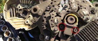
- Loose bearing holding the Hall sensor;
- Poor contact in the Hall sensor plug.
All these situations, in addition to poor sensor contact, are a signal to replace the distributor.
Unit location
Adjustment
In some cases, it is enough to adjust the ignition system to return the engine to its previous performance.
There are several symptoms that indicate this.
Symptom
Causes
Excessive detonation of the piston system
A characteristic feature of this problem is a ringing sound when you press the gas pedal. The reason is early ignition, which can cause deformation of the piston rings.
Black smoke from the chimney when starting the engine
This indicates that the ignition is too early.
Engine power has decreased, fuel consumption is increasing
Here the ignition is already late, so the mixture cannot burn completely
The engine begins to idle unevenly
Caused by both early and late ignition.
To adjust the distributor, you will need:
- Tachometer;
- Slotted screwdriver;
- Strobes;
- Wrench.
Let's get to work.
- Start the engine, increase idle speed to 800 units. Make sure that the engine temperature is at least 90 degrees.
- Align the crankshaft according to the marks on the cylinder block cover.
- Connect a 12 Volt light bulb to the output wire from the distributor. The second contact goes to ground.
- Turn on the ignition and watch the lamp. If it does not light up, loosen the nut that holds the distributor plate and begin to carefully, slowly turn the distributor body counterclockwise until the lamp lights up.
- Drive several kilometers at speeds up to 50 km/h. If the symptoms of the problem disappear, you have made the correct setting.
- If there are no consistent detonation sounds, you have set the ignition too late. Here the distributor needs to be turned clockwise.
- If there is no positive result, the distributor will have to be repaired or replaced.
Detailed structure and principle of operation of the distributor
Let's start looking at the VAZ 21093, distributor diagram (below) with a contact group:
Diagram of a VAZ distributor with a contact group
- The breaker is assembled from the following parts: housing (photo above), shaft, slider, contact plate with weights and springs, vacuum octane corrector, capacitor
- The shaft itself is made of two parts movably connected to each other
- There are cams on the upper or lower part of it, it all depends on the design, the number of cams corresponds to the number of cylinders
- Both parts of the shaft are movably connected to each other by means of a centrifugal octane corrector, which is assembled from cams, as well as springs of varying degrees of rigidity
- When the shaft rotates, the cams diverge under the influence of centrifugal force, while the springs stretch and only the upper part rotates relative to the bottom at a certain angle
- And the vacuum octane corrector is connected through a rod to a contact plate and a vacuum tube is connected to the intake manifold
- When the throttle valve opens, then the air vacuum in the intake manifold increases, which leads to the rotation of the movable contact plate relative to the cams
- To reduce sparking and increase the secondary voltage, there is a capacitor on the distributor body, which is connected to the electrical circuit parallel to the contacts
- And on the top of this shaft there is a rotor (popularly called “runner”), which is designed to distribute high voltage current to the spark plugs; distribution occurs through the terminals on the distributor cover
What is the difference between the distributor device on a VAZ 2109 with a hall sensor:
- The distributor of VAZ cars with a contactless ignition system is distinguished by the complete absence of contacts in its design; their role is played by an electronic switch
- Here, instead of contacts in the distributor, a sensor is installed, the operation of which is based on the effect discovered by Hall, who studied the behavior of semiconductors in an electromagnetic field
Hall Sensor
- A sensor with a special slot is installed on the movable plate of the distributor
- This slot contains a permanent magnet on one side and a semiconductor on the other side.
- A metal shutter is installed on the distributor shaft, having a rectangular slot, which during rotation passes through the sensor slot; it blocks the magnetic flux going to the semiconductor from the magnet
- At this time, the sensor stops passing the current passing through it to the switch
- Rotating further, the curtain passes the cutout past the sensor and then the semiconductor enters the field of action of the permanent magnet, and then passes a current that passes to the output of the switch
- And the switch, depending on this, opens or closes the power transistor, through which the terminal from the ignition coil is connected to ground
So we looked at the VAZ 2109 distributor device, and the principle of operation; in order to disassemble it and repair it, you will need another article. Drivers often have to deal with adjusting the ignition timing, I think it will be useful for you to know this too.
Dismantling
After dismantling the distributor, you can disassemble the device in order to repair its components, or completely replace the distributor with a new unit.
- De-energize the car by removing the negative from the battery;
- Disconnect the high-voltage components and the vacuum ignition corrector hose from the distributor;
- Remove the drive cable responsible for the throttle valves from the bracket. Next, the fastening nuts are unscrewed and the bracket is dismantled;
- Before removing the ignition distributor, apply a mark to the housing of the distributor and drive of auxiliary elements. This way you can simplify your task of setting the ignition timing for its precise setting. The mark is applied to the metal by scratching;
- Press the latch holding the block with the power wires and disconnect it from the distributor;
- Place the piston from the first cylinder to the top dead center position by moving the engine flywheel clockwise;
- Unscrew the remaining ignition distributor screws. The first fastener was removed when removing the damper cable sheath bracket;
- Remove your damaged distributor.
Disassembly and repair
Quite often, repair work with the distributor is associated with wear and the need to change the seals (coupling). To change the oil seal, as well as other failed components of the distributor, we bring to your attention the appropriate instructions, as well as video tips.
- Remove the ignition distributor cap by releasing the locking clip.
- Remove the slider. It is wiped with a clean rag and checked for mechanical damage. If there are chips or cracks, the element must be replaced.
- The runner must fit tightly on the shaft, which is achieved due to the presence of a plate spring with a pressing action. If it stretches or breaks, replace it.
- There is a resistor in the slider housing. The normal reading of its resistance is 1 kOhm. By measuring the data with an ohmmeter, you can draw conclusions regarding the performance of the component.
- Remove the low voltage wiring terminal. To do this, unscrew the mounting screw from the housing.
- Remove the plastic screen that serves as dust protection.
- A power wire comes from the Hall sensor and is held by the holder's claws. Using a screwdriver, the claws are opened and the wire is removed. Next, you need to unscrew the pair of mounting screws securing the Hall sensor support plate.
- Remove the vacuum corrector. Just be sure to disconnect it from the support plate lever before doing this. To perform this operation, carefully remove the retaining ring from the pin.
- The next step is to remove the pair of screws that hold the corrector to the distributor body.
Disassembling the unit
- Lift the corrector lever slightly, which will allow you to remove it from the sensor plate pin and remove the corrector itself.
- These steps will allow you to easily remove the support plate by lifting it with a flat head screwdriver. Remove the element. The plate must be replaced if the bushings are worn out or there is mechanical damage to the unit.
- Unscrew the two fasteners to disconnect the plate and the Hall sensor.
- You need to remove the oil seal, that is, the coupling. It is located on the distributor shaft. The coupling is closed with a thrust washer. That, in turn, is fixed with a retaining ring. You first need to remove the ring, which will make it possible to remove the thrust washer.
- Remove the oil seal by knocking out the pin with a small-diameter borer. Determine the dimensions of the boletus during the repair process.
Checking for damage
- There are adjusting washers under the oil seal.
- Remove the roller along with the centrifugal regulator from the distributor body.
- Clean the housing using kerosene and a dry cloth. Make sure that there are no mechanical damage, chips or cracks on the case.
- Examine the condition of the bushings. The roller rotates on them, and with severe wear, the roller begins to become loose. Also, the device is replaced along with the bushings if there are signs of wear, defects, or damage.
- To disassemble and replace damaged elements of the centrifugal regulator, you first need to remove the weight springs using a screwdriver.
- If the springs are intact and undamaged, not deformed, make notes on their seats. If you mix them up during assembly, problems may arise.
- Remove the driven plate along with the screen from the shaft.
- Make sure how effectively the weights move along their axes. Movements should be free, without any jamming. If there are problems, the weights are changed.
- It is a mistake to check the movement of loads without first removing and cleaning them.
As you disassemble the distributor, you will be able to identify damaged components and replace them with new ones using a repair kit. If the damage is serious, it is better to replace the entire ignition distributor.
The distributor is an important and sometimes capricious element. But replacing it and repairing it shouldn’t cause any problems.
Installing the ignition on a VAZ ninth model
When adjusting the ignition of a VAZ 2108-09-099 with a contactless ignition system, a strobe light is used. The sequence of actions is as follows:
- The vacuum corrector tube is disconnected, the strobe wires, observing polarity, are connected to the battery, the sensor is connected to the high-voltage wire of cylinder No. 1.
- After this, the sensor with the wire must be placed in the hole in the distributor cover, start the power unit and install the strobe light opposite the hatch with the scale, having previously removed the hatch cover. If the ignition setting of the VAZ 2109 is correct, the point on the flywheel will not reach the center mark of the scale, plus or minus one mark. Optimally, it will be located strictly opposite the central mark. If this is not the case, the ignition on the VAZ 2109 needs to be adjusted.
- To correctly set the ignition on a VAZ 2108 (2109, 21099), you need to turn off the power unit, release the distributor and move it clockwise, looking from the front left wheel, to increase the ignition timing of the mixture (earlier), and counterclockwise to decrease it angle (later ignition).
- After changing the angle, you should secure the distributor, put the vacuum tube on the vacuum corrector and check the torque again. If there is a repeated discrepancy with the optimal parameters, repeat the adjustment operation.
- Cylinder No. 1 is set to TDC on the compression stroke. You can verify this by removing the spark plug from cylinder No. 1 and tightly closing the threaded hole with a rolled paper ball or pressing it with your finger. Paper flying out or air escaping from under the finger when cranking the crankshaft manually will indicate the TDC of the piston at the end of the compression stroke. In this case, the mark on the crankshaft pulley must be aligned with the larger of the three marks on the cylinder block cover or, due to belt stretching, located behind it.
- The distributor is set to the zero position of the octane corrector. The contacts of the ignition distributor breaker should open at TDC of the first cylinder. A 12V test lamp with pieces of wire and clamps will help confirm this. The “positive” clamp is connected to the “positive” contact of the ignition coil, the “negative” - to the “ground” of the car.
- After this, you need to turn on the ignition. If the breaker contacts are open, the lamp will light up. If it does not light up, it is necessary to loosen the locking plate of the ignition distributor and slowly turn the distributor body in one direction and (or) the other until the control light comes on. The position of the distributor at which the lamp lights up (or goes out) will be the optimal ignition moment.
After finding it, you need to secure the locking plate without changing the position of the ignition distributor. If after adjusting the ignition the engine speed increases, it should be reduced to 800-900 rpm. Having completed the described steps, you need to make sure how the ignition on the VAZ is set when the car is moving using the method described above.
Causes of failure
There are several main reasons why a distributor may break and only need to be replaced:
- The appearance of cracks on the cover;
- Broken Hall sensor;
- Burnt out slider;
- Burnt contacts on the cover;
- Loose bearing holding the Hall sensor;
- Poor contact in the Hall sensor plug.
All these situations, in addition to poor sensor contact, are a signal to replace the distributor.
Unit location
Adjustment
In some cases, it is enough to adjust the ignition system to return the engine to its previous performance.
There are several symptoms that indicate this.
Symptom
Causes
Excessive detonation of the piston system
A characteristic feature of this problem is a ringing sound when you press the gas pedal. The reason is early ignition, which can cause deformation of the piston rings.
Black smoke from the chimney when starting the engine
This indicates that the ignition is too early.
Engine power has decreased, fuel consumption is increasing
Here the ignition is already late, so the mixture cannot burn completely
The engine begins to idle unevenly
Caused by both early and late ignition.
To adjust the distributor, you will need:
- Tachometer;
- Slotted screwdriver;
- Strobes;
- Wrench.
Let's get to work.
- Start the engine, increase idle speed to 800 units. Make sure that the engine temperature is at least 90 degrees.
- Align the crankshaft according to the marks on the cylinder block cover.
- Connect a 12 Volt light bulb to the output wire from the distributor. The second contact goes to ground.
- Turn on the ignition and watch the lamp. If it does not light up, loosen the nut that holds the distributor plate and begin to carefully, slowly turn the distributor body counterclockwise until the lamp lights up.
- Drive several kilometers at speeds up to 50 km/h. If the symptoms of the problem disappear, you have made the correct setting.
- If there are no consistent detonation sounds, you have set the ignition too late. Here the distributor needs to be turned clockwise.
- If there is no positive result, the distributor will have to be repaired or replaced.
Contactless ignition system BSZ
Installing contactless ignition is a really necessary thing. You will feel the difference! Two different contactless dispensers are available for Moskvich. They differ in sensors: ATE 2 with Hall, SOATE with induction. ATE 2 costs
1300 rub. Its kit includes a distributor, a coil, a commutator and a harness. It is installed on the RR 147 drive, if the RR 118, then you need to buy a drive as well. Don't forget to buy new silicone high-voltage wires.
The commutator is attached next to the coil. After installing all this on the car, do not forget to increase the spark gap of the spark plugs to approximately 0.8 mm.
Adapter for distributor from VAZ-2108 for Moskvich
The VAZ-2108 distributor can be installed using an adapter. This BSZ has been successfully operated for two years on two cars: M-412 (1.8 l.) and M 2141(2) (1.7 l.).
As a unit that transmits torque, a modified shaft from the old Moskvich drive and a shank with a pin from the original distributor are used, rotating in ball bearing No. 6203 and two starter copper-graphite bushings, the inner diameter of which, after pressing, expands to a diameter of 13 mm.
Since the inner diameter of the bearing and the diameter of the shaft are different sizes, an intermediate sleeve is pre-pressed onto the shaft.
The adapter flange is milled, as can be seen in the picture, holes are drilled and threads are cut for the screws.
ATTENTION! The adapter is designed to drive a new type of distributor, with a crimp clamp
Removal and disassembly of the ignition distributor sensor for VAZ 2108, 2109, 21099, 2110 cars
To replace the cover of the ignition sensor-distributor and the rotor (runner) of VAZ 2108, 2109, 21099, dismantling the ignition sensor-distributor is not required. Remove the central wire from the cover.
Using a Phillips screwdriver, unscrew the two screws securing the cover and remove it.
The cover can only be installed in one position. The wire socket of the first cylinder is marked with the number “1”.
The remaining wires are installed in accordance with the operating order of the cylinders - 1-3-4-2 (the direction of rotation of the slider is counterclockwise, when viewed from the side of the sensor-distributor cover).
By pulling, remove the slider from the shaft.
The slider is installed in only one position, when the slot on the shaft is directed in the direction opposite to the contact.
To dismantle the sensor-distributor, disconnect the hose from the vacuum regulator and the wire block.
Remove the cover. Using a 10mm wrench, unscrew the nut of the upper mounting of the sensor-distributor and remove the holder of the high-voltage wires.
After unscrewing two more nuts, remove the sensor-distributor.
The distributor sensor is sealed with a rubber ring, which we remove by prying it off with a screwdriver.
Remove the protective screen.
Unscrew the two screws securing the front bearing holder and the screw securing the block.
We remove the block.
Remove the lock washer of the vacuum regulator rod and unscrew the two screws securing it.
Remove the vacuum regulator.
Remove the front bearing holder with the Hall sensor.
Using a slotted screwdriver, unscrew the two screws and remove the Hall sensor.
Next, we disassemble the assembly to replace the centrifugal regulator or oil seal.
Using a screwdriver, remove the spring.
Using a rod with a diameter of 2.5 mm, knock out the pin.
We remove the coupling and adjusting washers, which should ensure that the axial play of the roller is no more than 0.35 mm.
We take out the centrifugal regulator.
We knock out the oil seal through two holes in the housing.
Washer and seal.
We press in the new oil seal with a piece of suitable pipe.
We install a washer on the oil seal and core it in several places.
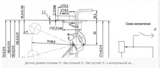
We assemble the distributor sensor in the reverse order, lubricating the working edge of the oil seal and bearing bushings with grease. Before installing the distributor sensor, put on the slider, but do not close the lid (or remove the cover if installing a new distributor sensor). We lubricate the rubber ring with engine oil, put the sensor-distributor on the studs and, turning the shaft by the slider, ensure that the protrusions of the coupling align with the slot of the camshaft. In this position, push the distributor sensor all the way and tighten the nuts. For the convenience of adjusting the ignition timing, there are divisions and “+” and “–” signs on the flange of the ignition sensor-distributor, and on the housing of the auxiliary units there is an adjusting protrusion. One division on the flange corresponds to eight degrees of crankshaft rotation. We align the protrusion on the housing of the auxiliary units with the middle of the scale on the sensor-distributor.
We tighten the nuts. We check and set the ignition timing using a strobe light. To do this, we connect the “+” terminal of the strobe to the “+” terminal of the battery, the “ground” clamp to the “–” terminal of the battery, and connect the strobe sensor to the high voltage wire of the 1st cylinder. We start the engine and direct the flashing stream of strobe light into the clutch housing hatch.
If the ignition timing is set correctly, then when the warm engine is idling, the mark on the flywheel should be opposite the slot in the clutch housing shield (see Checking the tension and replacing the timing belt). To adjust the ignition timing, stop the engine, loosen the nuts securing the ignition distributor and turn it to the required angle. To increase the ignition timing angle, turn the distributor sensor housing clockwise, and to decrease it, turn it counterclockwise (when viewed from the ignition sensor-distributor cover). Tighten the fastening nuts.
Replacing the front cuff
As mentioned above, replacing the front crankshaft oil seal on a VAZ 2109 is the most common and popular procedure, therefore, when carrying out repair work, it is very important to strictly follow all the recommendations of the manufacturer and be extremely careful, since the properties of the rubber from which the oil seal is made are such that it is very easy to damage during installation. There are two ways to replace the front crankshaft cuff: quick - “homemade” and recommended by the manufacturer.
First way
The method invented by the car owners themselves is as follows:
- Remove the timing belt;
- Using two screwdrivers/winders, remove the toothed pulley from the crankshaft, do not forget about its key;
Removing the crankshaft pulley and its key
- Using a hook or screwdriver, tear out the old cuff;
Taking out the old cuff
- We put the new cuff in place, and to make installation easier, lubricate its surface with oil;
- Using a mandrel, hammer it in until it stops.
Installing a new oil seal
Second way
When replacing the front crankshaft oil seal on a VAZ 2109, we will need the following:
- A pair of screwdrivers;
- Socket wrench set to “17”;
- Socket and open-end wrenches, as well as a “10” head;
- As a mandrel, the head is set to “27”;
- Timing pulley tensioner key;
- Since the “correct” replacement of the front cuff requires dismantling the oil pump, you need to stock up on a new gasket;
- And, of course, a new oil seal.
Next, you need to provide access to the engine crankcase, for which we put the car on an overpass or a lift, drain the oil and, as with any repair, disconnect the battery.
- If available, remove the engine protection, or rather its crankcase;
- Using a ten key, unscrew the four bolts securing the protective timing cover and remove it;
- We unscrew the six bolts securing the protective cover of the right half of the engine compartment using a key “8”;
- We remove the generator drive belt by loosening its tension with a key “17”;
- Remove the right front wheel;
- Having engaged a low gear, using a nineteen key, we “tear off” the bolt securing the pulley, then unscrew it and remove the pulley itself;
- We install the piston of the first cylinder at top dead center (attributable to the compression stroke). In this case, the installation marks on the rear protective casing and the camshaft drive must match, and the mark on the flywheel, visible through the clutch housing hatch, is located opposite the middle division of the installation scale.
Advice! You can turn the crankshaft by turning the hanging front wheel and engaging fifth gear.
- Using the key “17”, loosen the tension roller and remove the timing belt;
- We dismantle its lower cover from the clutch housing by unscrewing the four bolts securing it with a “10” key;
- Using a “10” head, unscrew the sixteen bolts securing the engine crankcase cover and remove it along with the gasket;
- Using the same head, unscrew the bolts securing the oil receiver to the oil pump and to the second main bearing, remove it;
- By analogy with the first method, use two screwdrivers to dismantle the toothed pulley (we also keep an eye on the key so as not to lose it);
- Using a “10” wrench, unscrew the 6 bolts of the oil pump (fastening it to the engine block)…
- ...and after tapping the pump housing, remove it together with the oil seal.
Removing the oil pump
We considered the further replacement process in the first option, but the assembly process itself occurs in the reverse order. Don’t forget to put a new gasket under the oil pump, having previously coated it with sealant (this makes it easier to install on the cylinder block).
Attention! When installing the oil pump, you must make sure that its guide pins fit into the corresponding technological holes in the engine cylinder block and that the working edge of the oil seal was not deformed during installation.
It is also advisable to install a fresh gasket under the crankcase cover.