Engine control system fuse box
Scheme
Designation
| 1 | 15A 1* ECM sensors Starter relay Canister purge valve |
| 1 | 7.5A 2* Controller |
| 1 | 3: Electric fuel pump relay (contacts) Electric fuel pump |
| 1 | 30A 4.5* Cooling fan |
| 2 | 15A 1* Injectors Ignition coils ECM controller Right electric fan relay Left electric fan relay |
| 2 | 15A 2* Electric fuel pump relay (contacts) Electric fuel pump |
| 2 | 30A 3* Reserve |
| 2 | 30A 4.5* Cooling fan |
| 3,4 | 30A 1* Electric fans (right, left) Right electric fan relay Left electric fan relay |
| 3 | 15A 2* Main relay |
| 3 | 15A 3* Controller |
| 3 | 15A 4* Ignition coil, power supply for fan relay control, controller, injectors |
| 3 | 15A 5* Ignition relay |
| 4 | 15A 3* Main relay Electric fan relay (winding) Electric fuel pump relay (winding) Vehicle speed sensor Canister solenoid valve Oxygen sensor Mass air flow sensor Controller |
| 4,5 | 30A 2* Electric fan relay (winding) (right, left) Electric fan motor (right, left) |
| 4 | 15A 4* Mass air flow sensor, phase sensor, heating oxygen sensor (two), canister purge valve, DS |
| 4 | 15A 5* Electric fuel pump |
| 5 | 15A 1* Electric fuel pump Electric fuel pump relay |
1* - 2021-2021, 2* - 2021-2021, 3* - 2007-2008, 4* - Cars with Bosch ME17.9.7/M74 controllers, 5* - Cars with 7.9.7 controllers.
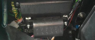
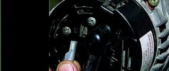
Engine Control Relay Box
It is located under the main fuse box and consists of 5 relays and 1 fuse.
Scheme
Electrical diagram of the block
Decoding
- Ignition relay
- Main relay
- Right cooling fan relay
- Left cooling fan relay
- Fuel pump relay
- Fuel pump fuse F5 15A
The only difference between Nivas with injection and carburetor systems is due to the fact that the engine control relay unit can be located under the hood of the car in a specially designated compartment.
Possible faults
To avoid problems with engine overheating, it is necessary to monitor and maintain the Niva’s cooling system.
You should check the antifreeze level in the expansion tank more often. Due to the reliability of cooling, there are not many malfunctions in it:
- When the car heats up to maximum in any weather, and the main radiator pipes are cold, the thermostat has broken. The element is not repaired, only changed.
- Electric fans turn on at random, including when the engine is cold, but if they overheat, they may not start. This means that the sensor transmitting temperature data to the controller has failed and must be replaced.
- When the indicator on the panel gives inaccurate data or does not show the temperature, you need to change the second sensor located in the cylinder head.
- The fluid level in the tank is constantly decreasing. It is necessary to look for and eliminate leaks in the pipes or in one of the radiators.
It is important to periodically check for play in the water pump shaft. Its appearance indicates wear of the bearing; it is necessary to change the pump as soon as possible.
Where are the blocks and relays located in Niva 21214 and 21213
The main power supply in these models is located under the lower edge of the instrument panel protection. Additional fuses in Niva 21214 for the injector are located to the left. This block is responsible for controlling fuel injection. There are also relays for monitoring the operation of the wipers and a set responsible for the motion control system.
Another fuse box is installed in the body to the left of the main one. They are responsible for the cooling system and how the engine works. There is also a diagnostic connector. The relay that controls the starter is located either next to the main power supply, or under the hood next to the brake fluid reservoir.
Replacing the heater valve VAZ 21214 Niva without draining antifreeze
Niva cars sometimes have problems associated with the failure of some parts of the cooling system, such as a thermostat or pump. If they break down, they are replaced as an assembly, fortunately they are not expensive. Also a common problem are leaking hoses or a cracked expansion tank, which also needs to be replaced.
But there is another problem with the VAZ 21214, a leaking heater valve. Because of this, there may be a smell of antifreeze in the cabin, wet floor mats on the front passenger side, or the heater may not work.
There are several ways to replace a faulty faucet:
- complete draining of antifreeze from the system;
- clamp the stove pipes with special clamps;
- Place your Niva on a slope, with the hood down.
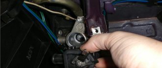
But there is another option that is more clear and simple. To do this, you need to disconnect the pipes going to the stove under the hood, point them upward and fix them in this position. The next step is to remove the stove itself:
- unscrew the console;
- disconnect the latches securing the stove;
- there is no need to disconnect the buttons;
- move the radiator assembly, along with the tap and pipes, towards the driver;
- we take out the entire structure through the space between the steering wheel and pedals;
- That's it, you can change the tap itself.
After replacement, reassemble in reverse order. As you can see, this operation is quite simple, and antifreeze will not leak into the cabin. And the procedure takes only 40 minutes, even for an unprepared person.
Main fuse box
Scheme
Purpose
| 1 | 16A Heater fan electric motor Relay (winding) for headlight wipers and electric motors for headlight wipers in all wipe positions except the initial Relay (winding) for turning on the rear window heating Electric motors for the rear window cleaner and washer Electric motor for the windshield washer |
| 1* | 16A Lamps Horns Socket Lighter Brake light lamps |
| 2 | 8A Relay and electric motor of the windshield wiper Turn signal lamps and relay-interrupter for direction indicators and hazard warning lights (in turn signal mode) Turn signal indicator lamp Tail lights (reversing light lamps) Generator excitation winding (when starting the engine) Differential lock activation indicator lamp in the transfer case Indicator lamp for turning on the parking brake Indicator lamp for the emergency condition of the service brake system Indicator lamp for insufficient oil pressure Fluid temperature indicator in the engine cooling system Fuel level indicator with a warning lamp for fuel reserve Indicator lamp for battery charge Indicator lamp for closing the carburetor air damper Tachometer Electric heater motor Relay headlight cleaners and washer (with the headlight cleaner and washer switch button not pressed) Headlight wiper electric motors in all brush positions except the initial one* |
| 3 | 8A Left headlight (high beam lamp) Indicator lamp for turning on the high beam headlights |
| 4 | 8A Right headlight (high beam lamp) |
| 5 | 8A Left headlight (low beam) |
| 6 | 8A Right headlight (low beam) |
| 7 | 8A Left front light (side light) Right rear light (side light) License plate lights Indicator lamp for turning on side lights |
| 8 | 8A Right front light (side light) Left rear light (side light) Instrument lighting lamp Heater control lever backlighting lamp Cigarette lighter lighting lamp Illumination lamps for switches and switches |
| 9 | 16A Direction indicators and relay-breaker for direction indicators and hazard warning lights Rear window heating element and relay (contacts) for its activation |
| 9* | 8A Warning lamp and oil pressure gauge Coolant temperature gauge Fuel level gauge with reserve warning lamp Parking brake warning lamp Brake fluid level warning lamp Turn indicators and corresponding warning lamp Carburetor choke control warning lamp Battery charge warning lamp Carburetor shut-off valve Tachometer Rear lights (reverse light) Differential lock warning lamp Turn signal relay interrupter Heated rear window (control circuit) |
| 10 | 16A Sound signal Cartridge for connecting a portable lamp Interior lamps Tail lights (brake lamps) |
| 10* | 8A Voltage regulator Generator excitation winding |
| 11 | 8A Turn signal lamps and relay-breaker for turn signals and hazard warning lights (in hazard warning mode) Rear fog lamp |
| 12 | 8A Daytime running light relay, daytime running light lamps |
| 12* | 8A Headlight cleaner and washer relay (with the headlight cleaner and washer switch button pressed) Headlight washer electric motor Headlight cleaner electric motors at the moment of start-up and when the brushes pass the initial position |
| 13 | 8A Rear lights (fog light lamps) Electric motors for headlight cleaners at the time of start-up and when the brushes pass the initial position Relays (contacts) for headlight cleaners Electric motor for headlight washers |
| 14 | 16A Cigarette lighter |
| 15 | 16A Backup Heated rear window (power circuit) |
| 16* | 8A Hazard warning switch and direction indicators in hazard warning mode Rear window wiper and washer |
Also interesting: Test: what should you buy, Renault Duster or Chevrolet Niva?
- KOLESA.ru - automobile magazine Fuse number 14 or number 1 at 16A is responsible for the operation of the cigarette lighter, depending on the year of manufacture.
Description of the injection engine
Repair of an injection engine, procedure for assembling and disassembling the Niva 2121 engine head, stages of removing and installing Niva 2131 valves, instructions for replacing the camshaft of Niva 2131, VAZ 2121.
Also interesting: Electrical diagram of VAZ 21214 Niva injector with description
Operation and maintenance of the fuel injection, ignition, exhaust system Niva 2121. Injection engine, carburetor engine. Design of the carburetor and injection power system of Niva 2131.
1 – oil pan; 2 – generator mounting bracket; 3 – cylinder block; 4 – power unit support cushion; 5 – power unit support bracket; 6 – clutch housing cover; 7 – flywheel; 8 – knock sensor; 9 – exhaust manifold; 10 – heat shield of the inlet pipe; 11 – inlet pipe; 12 – receiver; 13 – throttle assembly; 14 – fuel rail; 15 – cylinder head cover; 16 – outlet pipe of the cooling jacket; 17 – cylinder head; 18 – hydraulic chain tensioner; 19 – coolant pump pulley; 20 – camshaft drive cover; 21 – crankshaft position sensor; 22 – oil filter; 23 – crankshaft pulley mounting nut; 24 – crankshaft pulley; 25 – coolant pump cover; 26 – coolant pump housing.
Gasoline, four-stroke, four-cylinder, eight-valve, in-line, overhead camshaft.
The operating order of the cylinders is: 1–3–4–2, counting from the crankshaft pulley. Power supply system – distributed injection, Niva 2131 engine control – “BOSCH MP7.0” controller (Euro-2 toxicity standards). A catalytic converter is installed in the exhaust system.
On the right side of the engine (along the direction of the car) are located: a receiver with a throttle assembly, a throttle position sensor and an idle speed regulator, an intake pipe and an exhaust manifold, a fuel rail with injectors and a fuel pressure regulator, knock sensors and coolant temperature sensors (for the injection system) , generator, thermostat, starter (on the clutch housing). The air filter housing with mass air flow sensor is mounted on a separate bracket to the right of the engine.
On the left side of the engine are located: spark plugs and high voltage wires, an ignition module, an oil level indicator, an oil filter, coolant temperature and oil pressure sensors (control devices). Front: coolant pump and generator drive (V-belt), crankshaft position sensor.
The cylinder-piston group is the same as for the mod. 21213 (see VAZ-21213 engine). At the toe of the crankshaft there is a drive pulley for the generator and coolant pump with a toothed disk - for reading information by the Niva 2121 crankshaft position sensor. The disk has 58 teeth (the circle is divided into 60 teeth, but two are missing, forming a cavity - this is necessary to obtain a synchronization impulse each revolution of the crankshaft). Camshaft drive cover mod. 21214 is different from the cover mod. 21213 with a boss with a hole for the crankshaft position sensor.
The timing mechanism is driven by a single-row chain. Accordingly, the sprockets of the crankshaft and camshaft, as well as the oil pump drive shaft, are also single-row; they are not interchangeable with engine parts mod. 21213. At the same time, the number of teeth of the oil pump drive shaft sprocket was reduced from 38 to 30 (speed synchronization for the operation of the ignition sensor-distributor is not needed here), thereby increasing the performance of the oil pump (this is necessary in connection with the advent of a hydraulic chain tensioner and hydraulic mounts for valve levers) .
Tensioner shoe mod. 21214 is significantly longer than the shoe mod. 21213. It, like the chain guide, is made of wear-resistant plastic. Their attachment points have also been moved. The rotation axis of the tensioner shoe is located in the lower part of the cylinder block, to the right of the crankshaft sprocket (in its place in the engine model 21213 there was a limit pin).
The tensioner is spring-hydraulic: the preliminary tension of the chain (with the engine off) is provided by a spring, the working tension (after starting the engine) is by the pressure of oil under pressure, which is supplied through a steel tube from the adapter under the emergency oil pressure sensor.
Instead of adjusting bolts, the valve mechanism is equipped with hydraulic supports for the valve levers (hydraulic clearance compensators). They are powered by oil under pressure, supplied through a separate tube from the hole in the camshaft bearing housing near the middle stud of its mounting. Due to the fact that there are practically no gaps in the valve mechanism, the springs that press the valve levers on the mod engine are not installed. 21213. The shape of the camshaft cams is also different.
Additional relay block
This block is located above the gas pedal.
Scheme
Description
- Rear fog lamp relay
- Rear window heating relay
- Low beam relay
- High beam relay
A little higher, above the block, a relay can be installed - a breaker for the turn signals and hazard warning lights.
Separate fuses and relays can be installed under the hood: on cars with ABS, on the left side of the engine compartment near the ABS hydraulic unit, a block with fuses is additionally installed that protect the elements of the anti-lock brake system and the starter relay not far from the starter itself.
DIY power supply replacement
Below we will look at the process of replacing the power supply with your own hands. To replace, you will need a new power supply and a socket head set to “8”.
- First, open the hood and disconnect the battery.
- Now, under the instrument panel, find your power supplies. Using an “8” socket wrench, unscrew the two main nuts.
- Having done this, pry up the power supply and remove them from the studs.
- If you are replacing an old component with a new one, you must mark all the wires before doing so. Or take a new power supply unit and insert the wires from the old unit into it one by one. To remove the idle wires, pull them by their plugs.
- To check the functionality of the new power supply, reconnect the battery.
Replacing fuse Lada 2131 (VAZ 2131)
Every car has a fuse box that is responsible for the operation of certain components of the vehicle. If certain fuses fail, the operation of some elements becomes impossible, but if the unit itself breaks down, the vehicle simply will not be able to continue moving.
The fuse block (hereinafter referred to as the fuse block), unlike traditional models of the domestic automobile industry, is located in the vehicle interior. In particular, it is located on the driver's side under the steering wheel.
If any electrical circuit element in a car stops working (lamps, interior lights, heater, power windows), then car owners first check the power supply elements.
As a rule, the problem is resolved by replacing the fuse.
What does the power supply circuit itself look like? This question may be of interest to Niva owners. Below we will look at the electrical circuit of the unit with a description of all the components responsible for the operation of certain devices in the car.
In accordance with the diagram, we will consider the meaning of the BP elements. This electrical circuit is universal for all Niva cars.
It should also be noted that in VAZ 21214 injector cars there is another power supply unit with injection system components. It is located separately from the main power supply on the left side under the steering wheel.
In the case of the first described power supply unit, if the elements of the device begin to fail, this will in no way threaten the performance of the car, of course, with the exception of breakdowns of some components. However, in the case of the second power supply, if at least one component shorts out and does not work, the VAZ 21214 injector engine will not start.
Weaknesses of the VAZ 21214 engine
Cylinder block. This weak point appears on various models of Nivov engines, including the previously discussed 21213. Due to insufficient quality control, the assembly unit is manufactured with a high percentage of factory defects. In short, the drilling depth of the intake manifold stud holes is not maintained, causing the holes to meet the camshaft stud holes.
In this way, L-shaped through channels are obtained. After installing the studs at the factory, the connections remain sealed for some time and the problem is not identified when the quality control department employees accept engine tests. After the sale of new cars with low mileage, during sharp braking, oil begins to seep through the studs onto the hot intake manifold, so much so that smoke from the oil burning in the manifold pours out from under the hood, and accordingly, there is nothing to breathe in the cabin.
A sketch for the technical specifications for eliminating oil leaks from under the exhaust manifold studs.
- Remove the GC cover;
- Unscrew the two studs securing the bearing housing (see sketch) and remove oil from the threaded holes;
- Thoroughly degrease the holes and stud;
- Apply sealant UG-10 or its analogues to the lower threads of the studs;
- Place the studs in place;
- Tighten the bearing housing nuts;
- Install the cylinder head cover;
- Wait at least 30 minutes for the sealant to set.
- Water pump;
- Engine, manual transmission and transfer case oil seals;
- Generator;
- Starter;
- manual transmission;
- Valve cover gasket;
- Cooling system pipe connections;
- Radiator;
- Thermostat;
- Expansion tank;
- Vacuum brake booster.
Also interesting: Common Rail diesel engine power supply system: purpose and design
The water pump (pump) is characterized by frequent failures on new cars after 2,000 km.
Due to poor quality, oil seals require more frequent replacement than required according to the operating manual.
The generator has a high probability of failure. As a rule, it burns out even on new cars that have not reached 4,000-10,000 km.
The starter has a low service life without repair.
On a gearbox, one of the common defects is the fifth gear slipping out. In addition, the gears are not fully engaged.
The valve cover gasket loses its properties over time and allows oil to leak out.
The connections of the cooling system pipes in the places where the clamps are installed are not reliable and lose their tightness very early, which is fraught with loss of antifreeze.
The radiator is leaking. The problem occurs due to the appearance of cracks in the radiator pipe package, accompanied by loss of coolant. This defect has become widespread.
The thermostat does not provide thermal conditions for the coolant in the engine cooling system. The manifestation of this problem is no exception. The cause of the defect is a failure of the valve mechanism inside the thermostat. To check that the thermostat is working properly, after starting the engine, simply place your palm on the lower (outlet) hose, through which hot antifreeze circulates into the radiator for cooling. If the thermostat is working properly, after some time the hose should become hot; if the hose remains cold, the thermostat must be replaced.
The expansion tank cracks and antifreeze leaks out. The appearance of cracks occurs due to the failure of the steam-air valve in the tank plug due to increased pressure.
Vacuum brake booster (VUT). Manifested by a stiff brake pedal. The speed may fluctuate when the brake pedal is pressed, as well as hissing. The problem is solved by replacing failed rubber products and replacing clamps in connections.
Mounting blocks for lada 4×4 2021
The main and additional units are located in the cabin to the left of the steering wheel, under the instrument panel. The blocks contain fuses of the “Cylinder” size, ten and six fuses, respectively. The ratings and purpose of the fuses are indicated in Table 4 “Circuits protected by fuses”:
Fuse block of standard size “Standard”. The block is located on the left side under the upholstery and contains fuses that are designed to protect engine control system devices. The ratings and purpose of the fuses are shown in Table 5:
The fuse and relay box is located on the left side of the steering column under the instrument panel. The block contains two “Standard” size fuses, which are designed to protect the circuits of the electric fuel pump, electric windows and electric mirrors. The ratings and purpose of the fuses are shown in Table 6:
The fuse and relay box is located on the right side of the steering column under the instrument panel. The block contains one “Maxi” size fuse and two “Standard” size fuses, which are designed to protect the circuits of the hydraulic unit of the anti-lock braking system. The ratings and purpose of the fuses are shown in Table 7:
Purpose of fuses, relays and their replacement Niva VAZ 21213, 21214, 2131 lada 4×4
Note. Keep in mind that the location and purpose of fuses has changed and continues to change, depending on the year of manufacture and modification of the car. This page presents several options, be careful!
If the fuse fails again, contact your LADA dealer to find out and eliminate the reasons that caused it to melt.
It is unacceptable to install a homemade jumper or a fuse of a different rating to replace the blown one.
Content:
Fuse locations in the interior and under the hood (from 2020) Main fuse locations (until 2022) Additional relay boxes Additional fuses and relays for vehicles with ECM Additional fuses for vehicles with ABS Additional fuses for Urban equipment Replacement of fuses
Also interesting: Lada Niva 2022 review, configurations and prices, specifications | Major Lada is the official dealer of VAZ in Moscow
Fuse and relay locations (from 2022)
Fuses and relays are located in two blocks: in the passenger compartment (Fig. 48) and in the engine compartment (Fig. 49).
When replacing fuses and relays, use only new fuses and relays that are marked in accordance with tables 1 and 2. To avoid melting of the insulation of the wires and the housing of the mounting block when operating the vehicle, you should use only types of fuses and relays approved for use by AVTOVAZ JSC, according to Tables 1 and 2.
Fuse and relay box in the passenger compartment
Rice. 50. Diagram of the mounting block in the cabin with numbering of fuses and relays
Table 1
| FUSES IN THE PASSENGER BLOCK | ||
| Fuse number | Denomination | Protected Circuits |
| F12 | 7.5A | Power supply for air flow sensor, phase sensor, upper and lower oxygen sensors, canister purge valve |
| F13 | 15A | Power supply for the rear wiper and washers of the front and rear windows |
| F14 | 15A | Power socket 12 V trunk |
| F15 | 15A | Power supply for front seat heaters |
| F16 | 25A | Power supply for front windows and side mirror controls |
| F17 | 15A | Front wiper power supply |
| F18 | 15A | Radio power supply |
| F19 | 20A | Power supply for the first and second 12 V sockets in the cabin |
| F20 | 15A | Air conditioner clutch power supply |
| F21 | 5A | Power supply K15 for ABS hydraulic unit |
| F22 | 20A | Rear window defroster power supply |
| F23 | 20A | Power supply for interior heater fan |
| F24 | 5A | Power supply for reverse lamp and K15 radio signal |
| F25 | 10A | Power supply for hazard warning lights and instrument cluster |
| F26 | 7.5A | Signal K15 alarm and instrument cluster |
| F27 | 7.5A | Power supply unit SNPB |
| F28 | 5A | Brake and clutch switch signal |
| F29 | 15A | Power supply for fuel pump and diagnostic connector |
| F30 | 10A | Power supply for rear fog lights |
| F31 | 7.5A | Power supply for fog lights |
| F32 | 10A | Power supply for left side lights, license plate light and trunk light |
| F33 | 7.5A | Power supply for right side lights and interior illumination of controls |
| F34 | 10A | Power supply for daytime running lights (DRL) |
| F35 | 10A | Power supply for the DS lamp of the left headlight |
| F36 | 10A | Power supply for the BS lamp of the left headlight |
| F37 | 10A | Power supply for the BS lamp of the right headlight |
| F38 | 10A | Power supply for the right headlight DS lamp |
| F39 | 5A | Air conditioner panel power |
| F40 | 7.5A | Power supply for side mirror heaters |
| F41 | 7.5A | Power supply for brake lights and DST |
| F42 | 5A | Power supply for interior lighting |
| RELAY IN THE SALON BLOCK | ||
| Relay number | Denomination | Relay purpose |
| K5 | Z0A | Starter activation relay |
| KB | 40A | Ignition switch unloading relay |
| K7 | 20A | Left and right headlight switch relay |
| K8 | 20A | Relay for turning on BS left and right headlights |
| K9 | 20A | Fuel pump relay |
| K10 | 20A | ECM main relay |
| K11 | 20A | Front seat heating relay |
| K12 | 20A | Air conditioning clutch activation relay |
| K13 | 20A | Heater fan relay |
| K14 | 20A | Left DRL activation relay |
| K15 | 20A | Right DRL activation relay |
| K16 | 20A | Heated rear window relay |
Fuse and relay box in the engine compartment
Rice. 51. Diagram of the mounting block in the engine compartment with numbering of fuses and relays
table 2
| FUSES IN THE ENGINE COMPARTMENT BLOCK | ||
| Fuse number | Denomination | Protected Circuits |
| F1 | 60A | Battery protection against generator short circuit |
| F2 | 60A | Battery protection against generator short circuit |
| F3 | 40A | Power supply to the interior mounting block |
| F4 | 40A | Power supply for hydraulic pump of ABS hydraulic unit |
| F5 | 30A | Top Radiator Fan Power |
| F6 | 30A | Lower radiator fan power supply |
| F7 | 25A | Power supply for ABS hydraulic unit solenoid valves |
| F8 | 25A | General power supply for external lighting equipment |
| F9 | 20A | ECM power supply |
| F10 | 15A | Horn power supply |
| RELAY IN ENGINE COMPARTMENT | ||
| Relay number | Denomination | Relay purpose |
| K1 | 40A | Top fan relay 1 |
| K2 | 40A | Relay 2 for switching on the top fan |
| KZ (yellow) | 40A | Relay 3 for turning on the lower fan |
Fuse protected circuits (until 2022)
Fuses do not protect the electrical circuits of ignition, engine start, generator (except for the field winding), low beam headlight relay, high beam headlight relay.
Please note that the rating and purpose of fuses may vary depending on the year of manufacture of the vehicle. Therefore, explanatory tables 3 and 4 are presented in two versions.
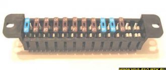
Most fuses are located in blocks located in the passenger compartment under the instrument panel, to the left of the steering column. The fuses are installed in two blocks side by side, they are connected to each other (Fig. 44) and are held in them by spring contacts. There are ten fuses in the upper block and six fuses in the lower block. The circuits they protect are listed in Table 3.
Rice. 44. Fuses (appointment is indicated in table 3)
Additional fuse and relay blocks
Relay block under the instrument panel, above the gas pedal: 1 - rear fog light relay; 2 — relay for turning on the heated glass of the luggage compartment door; 3 — low beam headlight relay; 4 - high beam headlight relay
Additional blocks for vehicles with ECM
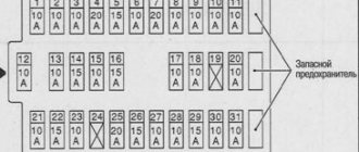
On vehicles with an ECM, a block (Fig. 45) with four fuses is additionally installed on the left side of the front end under the instrument panel, which protect the elements of the injection systems. (to the right of them is the diagnostic connector) A faulty fuse is determined by the failed circuits that it protects, in accordance with Table 4.
TABLE 4 (for Fig. 45)
To connect and protect the ECM circuits, a “safety line” type wire is used, which is part of the ignition system wiring harness and is connected directly to the battery. The circuits protected by this wire are listed in Table 5.
Table 5
| Fuse | Protected circuit |
| Safety line type wire | ECM main relay |
| Diagnostic block | |
| APS | |
| Fuses 1, 2, 5 of the injection system (see table 4, 2nd option) |
On vehicles with ABS, a fuse block is additionally installed on the left side of the engine compartment near the ABS hydraulic unit, which protects the elements of the anti-lock brake system. Fuse ratings are shown in Table 6.
Also interesting: Fuses Niva 21214 injector "
Table 6
In the LADA 4×4 Urban configuration, the electrical equipment has additional circuits protected by fuses, the list of which is indicated in Table 7. And the list of main fuses is the same as for the regular LADA 4×4 configuration.
Table 7 (additional fuse circuits in the Urban package)
* For LADA 4×4 Urban cars. ** For LADA 4×4 vehicles with air conditioning.
Disconnect the negative cable from the battery. By pulling the latch located on top of the main fuse box cover...
Similarly, remove the cover of the additional fuse box.
Video
VAZ 21214 engine modifications and their differences
| Motor modification | Availability of power steering | An exhaust manifold | EURO environmental class |
| 21214-41 | welded from stainless steel become | 3 | |
| 21214-34 | _ | cast iron | |
| 21214-33 | |||
| 21214-32* | |||
| 21214-31 | welded from stainless steel become | 4 | |
| 21214-30 | — |
*21214-32 – has fuel pipes with quick connectors, a flywheel for the clutch of 215 mm (200 mm on other models).
The geometry of the cylinder block 21214 and 21213 is the same. There are no liners in the cylinders. Due to the use of an ejector, the configuration of the front engine cover has been changed to accommodate the installation of a crankshaft position sensor. To mount the power steering, a hole is made on the block for installing a bracket; in addition, there is a threaded hole for installing a knock sensor, as well as threaded holes with studs for mounting the ignition module bracket.
The ShPG came from 21213. Crankshaft 21213-1005015 sets the piston stroke to 80mm. The crankshaft pulley is distinguished by the presence of teeth along the outer diameter for the operation of the crankshaft position sensor. The latest internal combustion engine models are equipped with a damping pulley (21214-1005058-10). The presence of a damper made it possible to reduce the load on the crankshaft to prevent cutting of the key, and also make the operation less noisy.
Cylinder head 21214-1003011-30 (36) was modified from the head from 21213. For modification, it was necessary to introduce holes for installing a phase sensor and studs for mounting the intake receiver. To install hydraulic compensators, bosses are cast in the head and have threaded holes in them. With the introduction of hydraulic thermal gap compensators, adjusting bolts were eliminated from the head design.
Oil under pressure is supplied to the hydraulic compensators through separate pipes. There are two types of heads: Russian 21214-1003015 and Canadian 21214-1003015-30. The differences between the heads are as follows: in the first, the diameter of the threads in the holes for hydraulic compensators is M18/1.5, the wells for hydraulic compensators do not have drainage holes;
the second ones have M24x1.5 holes, and the wells have drainage holes (the markings are made in the casting). Interchangeability of heads, as well as hydraulic supports of old and new designs, is not possible. A new oil rail 21214-1007180-30 made of stainless steel is used, supplying oil to the hydraulic compensators. Interchangeability with ramp 21214-1007180 is maintained.
Valve levers 21214-1007116-30, in contrast to the previous 2101-1007116, have a smaller radius (11 mm) of the platform support interacting with the camshaft cam, as well as an additional groove on the side of the hydraulic compensator. Both lever options are interchangeable.
In the timing camshaft drive, instead of a double-row chain, a single-row chain 21214-1006040-03 is used on rollers and bushings. Single-row sprockets for the chain are taken from the 2123 engine. The oil pump sprocket has the number of teeth reduced to 30 to increase the performance of the oil pump and improve the operation of the hydraulic chain tensioner and hydraulic compensators.
The camshaft 21214-1006010 is original with a modified cam profile and can be interchanged with the shaft from 21213.
The 80 amp generator is the same as the 2112, with a slight difference in the diameter of the pulley 80 mm for the drive belt 2107-1308020 (944 mm).
The exhaust manifold can be made of cast iron or stainless steel. The cast iron manifold is made by casting. The stainless steel manifold version has a welded design. A welded manifold is lighter and heats up quickly, which is good for the operation of the catalyst located in the manifold. In addition, an oxygen sensor is installed in the exhaust manifold.
The intake manifold and fuel rail (2123-1144010-11) were borrowed from the 2123 engine. The injectors of the fuel injection system are SIEMENS VAZ 20734 (yellow), injectors (0280 158 110) were installed on early engines.
Ignition module from engine 2112.
Electronic control is carried out by the BOSCH MP 7.9.7 ECU. or JANUARY 7.2 depending on the year of manufacture and modification of the internal combustion engine.
The cooling system began to be assembled using gaskets with an elastic polymer bead, which improved the tightness of the system. The water pump (pump) includes an oil seal (cuff) that is more resistant to wear and loss of properties.
Diagram for switching on the dimensions of the Niva 21213 car |
Scheme for switching on the external lighting (dimensions) of the Niva 21213 car
Elements of the diagram for switching on the dimensions of the Niva 21213 car
1. Side lamps in the front lights of the car. 2.Fuse block. 3.Outdoor lighting switch. 4. Instrument lighting switch. 5. Indicator lamp for turning on the dimensions in the instrument cluster. 6.License plate lights. 7. Side light lamps in the rear lights.
A - to the lighting lamps of the instrument cluster, switches and backlight display.
Notes and additions
More diagrams of the Niva 21213 car
— Connection diagram for low and high beam headlights Niva 21213
— Wires for the rear lights of the Niva 21213 car, diagram
— Connection diagram for generator 9412.3701 for Niva 21214
— Body clearances of the Niva 21213 car, diagram
— Connection diagram for direction indicators Niva 21213
Recommendations
I replaced the ignition switch contact group, now everything works as before!Thanks for the advice!
And also interesting: Do-it-yourself modifications to the Niva 2121 “
The dimensions from the factory work without ignition. I often forget to turn it off, I lock the car, and the lights are on and the lights are on. Of course there is no stove.
And in principle, you shouldn’t turn on the heater fan until you start the engine!
And my dash doesn't light up and the heater fan doesn't work when the ignition is off. How it should be!
The tidy should light up when the lights are turned on.
It doesn't light up for me. Only when the ignition is turned on.FLASH-X3!
Either there is a problem in the lock, or in the button for turning on the dimensions (headlights), there is simply nothing to break.
The heater fan will never run without ignition. Not provided.
The backlight has a power supply system independent of the ignition.
The key in the ignition switch must be turned to marks III and I. If the key is at mark 0, nothing will work. Even the light.
If the key is in the required (III and I) position and nothing works... there may be either problems with the lock or contact group, or the wires are mixed up when connecting, if the lock was turned off.
thanks, do you think it’s the ignition switch? I’m just leaning towards that too...
The heater fan will never run without ignition. Not provided.
The backlight has a power supply system independent of the ignition.
The key in the ignition switch must be turned to marks III and I. If the key is at mark 0, nothing will work. Even the light.
If the key is in the required (III and I) position and nothing works... there may be either problems with the lock or contact group, or the wires are mixed up when connecting, if the lock was turned off.
I have a 21st Niva
It doesn't matter what kind of field. The electrics on all classic vases are similar and unchanged. And the stove motor does not turn on without the ignition.
I understood why I thought it was turned on.
The heater fan will never run without ignition. Not provided.
The backlight has a power supply system independent of the ignition.
The key in the ignition switch must be turned to marks III and I. If the key is at mark 0, nothing will work. Even the light.
If the key is in the required (III and I) position and nothing works... there may be either problems with the lock or contact group, or the wires are mixed up when connecting, if the lock was turned off.
Without a key, I only have stoplights that light up when I press the brake pedal)
My car works halfway without a key.
The heater fan will never run without ignition. Not provided.
The backlight has a power supply system independent of the ignition.
The key in the ignition switch must be turned to marks III and I. If the key is at mark 0, nothing will work. Even the light.
If the key is in the required (III and I) position and nothing works... there may be either problems with the lock or contact group, or the wires are mixed up when connecting, if the lock was turned off.
The problem was solved by replacing the ignition switch contact group!thanks for the advice)
Read news about the new Niva
- Diagram and location of the fuse box Niva VAZ-21213 and 21214
- The modernized Lada Niva Legend (4x4) 2021 was shown on the Internet
- Lada 4×4 Bronto - sales stopped, new details » Lada.Online - all the most interesting and useful about LADA cars
- Description of the instrument panel Lada 4×4 (VAZ 2121, 2131) » Lada.Online - all the most interesting and useful about LADA cars
- LADA Niva – Operating manual – Official LADA website
- Chevrolet Niva gasoline consumption per 100 km
- Buy LADA (VAZ) 2131 (4×4) 2022 in Rostov-on-Don, low price for Lada 2131 (4×4) 2022 on the Avto.ru website
- Diagram and location of the fuse box Niva VAZ-21213 and 21214
Technical characteristics of the internal combustion engine VAZ 21214
| Volume, cm3 | 1690 |
| Main fuel: | gasoline AI-92 |
| Max. power, l. With. | 83 (at 5200 rpm) |
| Max. torque, Nm | 127 (at 3000 rpm) |
| Cylinder block configuration: | in one row |
| Number of cylinders | 4 |
| Number of valves | 8 |
| Max. speed, km/h | 153 |
| Acceleration time to 100 km/h, sec. | 17 |
| Combined fuel consumption | 11,5 |
| Econorm | Russia-83 |
| Cylinder diameter, mm | 82 with deviation up to 0.05 |
| Piston stroke, mm | 80 |
| Repair dimensions of pistons and cylinders, mm: | |
| first repair (marking on the piston - triangle, on the rings - 40) | 82.4 |
| second repair (marking on the piston - square, on the rings - 80) | 82.8 |
| Repair measurement of the diameter (for boring) of the crankshaft supports | 54.52 with deviation up to 0.013 |
| Compression ratio | 9,4 |
| Supply system | two-barrel carburetor |
| Cooling | liquid |
| Valve mechanism | SOHC |
| Cylinder block material | cast iron |
| Presence of liners in cylinders | not provided for by design |
| Head material | aluminum alloy |
| Resource before major overhaul, km | 80,000 (actual ≈ 120,000 km) |
| Number of bars | four |
| Cylinder operating order | 1-3-4-2 |
| Max. speed, rpm | 8000 |
| Weight, kg: | 117 |
| Volume, cm3 | 1690 |
| Poppy. power, l. With., | 83 |
| Max. torque, Nm | 129 |
| Arrangement of cylinders in the block | in-line |
| Cylinders, pcs. | 4 |
| Valves, pcs. | 8 |
| Max. speed, km/h | 142 |
| Acceleration to 100 km/h | 17 |
| Combined fuel consumption | 10 |
| Environmental standards | EURO-4 |
| Cylinder diameter, mm | 82 |
| Piston stroke, mm | 80 |
| Compression ratio | 9,4 |
| Supply system | distributed injection |
| Cooling | liquid |
| Valve mechanism | SOHC |
| Cylinder block material | cast iron |
| Cylinder head material | aluminum |
| Resource, km | 80,000, in fact up to 150,000 |
| Clock (number of clock cycles) | 4 |
| Cylinder operating order | 1-3-4-2 |
| Max. c/v speed, rpm | 8000 |
| Recommended fuel | unleaded gasoline AI-95 |