Share:
This article shows the fuse box of cars of various brands. The fuse box diagram is presented for various cars. The location of the fuse box is shown. The decoding of the fuse box is presented in tabular form. The pinout of the fuse box of some machines is described in detail. The fuse box of several VAZ models is described.
Name of the fuse and relay box for the following vehicles:
- Fuse box UAZ Simbir 3162, 31602 Fuse box decoding
- Fuse box diagram for UAZ Simbir 3162, 31602
- Electrical protection unit for the all-terrain vehicle UAZ Patriot 316300 since 2005
- Package of electrical fuses for cars UAZ-374195, UAZ-396295, UAZ-396255, UAZ-390995, UAZ-220695 Loaf and UAZ-330395, UAZ-330365, UAZ-390945 Tadpole 2011
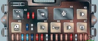
Fuse box UAZ Simbir 3162, 31602
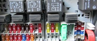
Designation in the fuse box picture:
- K2 - windshield wiper relay;
- K3 — direction indicator stick;
- K4 — electric relay for low-beam headlights;
- K5 — switch for turning on high-beam headlamps;
- K6 - additional (unloading) switch;
- K7 - solenoid for turning on the rear window heating;
- K8 - electromagnet for turning on fog lamps;
- F1-F23 - fuses (see table)
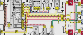
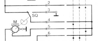
Fuse block diagram:
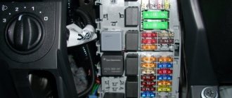
The power unit is installed in the car interior, on the left, under the instrument panel, opposite the driver’s seat.
Healthy ! Crankshaft sensor
Decoding the fuse box UAZ Simbir 31602:
| Designation | Current strength, A | Protected Circuits |
| Assembly electrical module | ||
| F1 | 5 | Instrument lighting, left side side lights |
| F2 | 7,5 | Low beam of the right electric headlight |
| F3 | 10 | Far illumination of the right lamp |
| F4 | 10 | Right fog light |
| F5 | 30 | Glass door lift system, electric sunroof drive |
| F6 | 15 | Portable lamp socket |
| F7 | 20 | Horn, electric mirrors |
| F8 | 20 | Rear window heating element |
| F9 | 20 | Glass cleaners and washers |
| F10 | 20 | Reel for headlamp cleaners |
| F11 | 5 | Side lights, right side, license plate light |
| F12 | 7,5 | Near left headlamp |
| F13 | 10 | Left high-beam light and high-beam indicator |
| F14 | 10 | Left fog light |
| F15 | 20 | Door lock system |
| F16 | 10 | Hazard warning and direction indicators |
| F17 | 7,5 | Courtesy lights, engine compartment lamp, brake light switch |
| F18 | 25 | Heater, cigarette lighter, rear window defroster switch |
| F19 | 10 | Instrument cluster, reverse light switch, on-board control system |
| F20 | 7,5 | Rear fog |
| F21 | 10 | Backup electrical fuse |
| F22 | 20 | Spare electrical plug |
| F23 | 30 | Emergency traffic jam |
The main relay 90.3747-10 (RF) is located on the front panel, above the engine, next to the fuel pump relay.
The fuel pump solenoid type 90.3747-10 (RF) is installed on the bulkhead, above the engine, next to the main electromagnet KMPSUD and the intermediate starter switch (retractor solenoid).
The intermediate starter relay is installed on the front panel, above the engine, next to the main relay KMPSUD and the fuel pump relay.
The main solenoid circuit coming from the battery is protected from short circuits to ground by a 20 A harness fuse type 688670-7 (AMP) or 354.3722 (RF). At the same time, the KMPSUD ignition circuit is protected from short circuits to ground by a 10 A harness fusible plug of type 688670-5 (AMP) or 352.3722 (RF). The plugs are placed in blocks that are attached:
- 20A - to the main relay;
- 10A - to the electric fuel pump relay.
Healthy ! Camshaft sensor
Starter, ignition, rear fog lamp relay
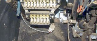
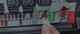
In order to carry out quick checks and repairs, the ignition system relay is installed under the front dashboard of the car, behind the hood release handle. It is located just below the central dashboard. The module is closed with a plastic plug, which must be opened slightly to test for functionality.
Starter, ignition, rear fog lamp relay
Next to the indicated relay, there is a similar one for the rear fog lights and the starter.
The main task of the relay when igniting is to reduce the applied load to the contacts. When the engine starts, the relay turns off some electrical circuits in the vehicle system. The system is used not only in injection, but also in carburetor engines.
In the event of a malfunction or malfunction in the ignition system, it is necessary to monitor the operation of the relay. For this purpose, open the box and carefully remove the desired element. It is attached using contacts to special grooves. The first thing to do is look at the oxidation of the contacts, if necessary, clean them with a soft cloth or treat them with a special liquid.
To check functionality, you need to use a regular multimeter. We connect to incoming connections and check the numbers. If there is no short circuit when current is applied, it means the element is not working. Replacement is carried out in a similar manner. It is necessary to use a standard element with the number of amperes indicated on the housing.
Fuse box UAZ Patriot
Fuse box UAZ Patriot 316300 from 2005
- K2 — windshield wiper relay;
- K3 - turn signal interrupter relay;
- K4 - relay for low beam headlights;
- K5 - headlight high beam relay;
- K6 - additional (unloading) relay;
- K7 — relay for turning on the heated rear window;
- K8 - relay for turning on fog lights;
- F1-F23 - fuses (see table)
- K1 - starter relay;
- K2 — rear door windshield washer time relay;
- K3 - relay for the electric fan of the engine cooling system;
- K4 - sound signal relay;
- K5 - electric fuel pump relay;
- K6 - relay KMPSUD;
- F1-F5 - fuses (see table).
Decoding of the fuse box of UAZ Patriot 316300 from 2005:
Healthy ! temperature sensor
| Designation | Current strength, A | Protected Circuits |
| Mounting block | ||
| F1 | 5 | Instrument lighting, left side side lights |
| F2 | 7,5 | Low beam right headlight |
| F3 | 10 | High beam right headlight |
| F4 | 10 | Right fog lamp |
| F5 | 30 | Electric door window system, electric sunroof |
| F6 | 15 | Portable lamp socket |
| F7 | 20 | Horn, electric mirrors |
| F8 | 20 | Rear window heating element |
| F9 | 20 | Glass cleaners and washers |
| F10 | 20 | Reserve |
| F11 | 5 | Side lights, right side, license plate light |
| F12 | 7,5 | Low beam left headlight |
| F13 | 10 | Left high beam and high beam warning light |
| F14 | 10 | Left fog lamp |
| F15 | 20 | Electric door lock system |
| F16 | 10 | Hazard warning and direction indicators |
| F17 | 7,5 | Courtesy lights, engine compartment lamp, brake light switch |
| F18 | 25 | Heater, cigarette lighter, heated rear window switch |
| F19 | 10 | Instrument cluster, reverse light switch |
| F20 | 7,5 | Rear fog lights |
| F21 | 10 | Spare fuse |
| F22 | 20 | Spare fuse |
| F23 | 30 | Spare fuse |
| Relay and fuse box | ||
| F1 | 10 | Electric fuel pump relay power circuit |
| F2 | 20 | KMPSUD relay power circuit |
| F3 | 20 | Starter relay power circuit |
| F4 | 25 | Fan relay power circuit |
| F5 | 80 (90) | Mounting block power supply |
Fuse box UAZ Patriot 316300 from 2007
Fuse block diagram:
- K2 — windshield wiper relay;
- K3 - turn signal interrupter relay;
- K4 - relay for low beam headlights;
- K5 - headlight high beam relay;
- K6 - additional (unloading) relay;
- K7 — relay for turning on the heated rear window;
- K8 - relay for turning on fog lights;
- F1-F23 - fuses (see table)
- K1 - starter relay;
- K2 — rear door windshield washer time relay;
- K3 - sound signal relay;
- K4 - relay KMPSUD;
- K5 - electric fuel pump relay;
- K6 - electric fan relay;
- K7 - electric fan relay;
- F1-F10 - fuses (see table)
- K1 - relay for turning on the interior heater fan;
- K2 - recirculation damper relay 1;
- K3 - recirculation damper relay 2;
- K4 - compressor clutch relay;
- K5 - fan relay 1;
- K6 - fan relay 2;
- F1-F3 - fuses (see table)
Healthy ! Throttle sensor
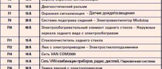
Explanation of the fuse box:
| Designation | Current strength, A | Protected Circuits |
| Mounting block | ||
| F1 | 5 | Lighting of switches and controls, side lights of the left side |
| F2 | 7,5 | Low beam right headlight |
| F3 | 10 | High beam right headlight |
| F4 | 10 | Right fog lamp |
| F5 | 30 | Electric door window system, electric sunroof |
| F6 | 15 | Portable lamp socket |
| F7 | 20 | Sound signals, electric mirrors |
| F8 | Heated rear window, exterior mirrors MUS | |
| F9 | 20 | Window cleaners and washers, additional interior heater |
| F10 | 20 | Cigarette lighter |
| F11 | 5 | Side lights, right side, license plate light |
| F12 | 7,5 | Low beam left headlight |
| F13 | 10 | Left high beam and high beam warning light |
| F14 | 10 | Left fog lamp |
| F15 | 20 | Electric door lock system |
| F16 | 10 | Hazard warning and direction indicators |
| F17 | 7,5 | Courtesy lights, brake light switch |
| F18 | 25 | Heater, switch for heated rear window and exterior mirrors |
| F19 | 10 | Instrument cluster, reverse light switch |
| F20 | 7,5 | Rear fog lights |
| F21-23 | 10; 20; 30 | Spare fuses |
| Relay and fuse box | ||
| F1 | 30 | Fan relay power circuit |
| F2 | 25 | Anti-lock braking system (ABS) |
| F3 | 5 | Devices |
| F4 | 10 | Electric fuel pump relay power circuit |
| F5 | 20 | Starter relay power circuit |
| F6 | 30 | Fan relay power circuit |
| F7 | 20 | Power circuit of relay KMPSUD |
| F8 | 10 | Anti-lock braking system (ABS) |
| F9 | 80 (90) | Mounting block power supply |
| F10 | 40 | Anti-lock braking system (ABS) |
| Relays and fuses | ||
| F1 | 7,5 | A/C compressor clutch |
| F2, F3 | 30 | Fan 1, Fan 2 |
Mounting fuse block UAZ Patriot 2022
| On this model of the UAZ Patriot 2118 SUV there are two mounting blocks of fuses and relays. Their installation locations are presented here. Images and diagrams of the location of fuses and relays are posted. The explanations of all blade fuses and relays that are equipped with the mounting blocks are summarized in tables. They describe which electrical circuits a particular fuse protects and which device protects this or that relay. |
Latest news about Lada Vesta Cross
Nowadays, AvtoVAZ produces cars of a completely different level of comfort and reliability, just like the Lada Vesta car model range: modern appearance of the sedan, a variety of body colors, a variety of configuration options, a thoughtful interior and modern electronics. If over the course of several years they have managed to get used to the sedan, then many people are looking forward to the Lada Vesta Cross model and are monitoring the emergence of new information.
Lada Vesta is equipped with many electrical appliances, each of which is vulnerable to voltage surges. To protect consumers, there is a fuse in the circuit of each of them, and if for some reason it blows, it will have to be replaced, otherwise the electrical appliance will not work. Just first you need to find the Lada Vesta fuse box.
VAZ 2114 fuse box
| A view of the fuse box and its diagram are located here. The installation location of the VAZ 2114 fuse box is indicated. Its electrical circuit is located. The designation of each fuse and relay, as well as which electrical circuit they protect, is summarized in the table. Here the pinout of this block is laid out and each contact of the connecting sockets (Plugs) is described in detail. At the end there are detailed instructions for replacing the VAZ 2114 fuse mounting block. |
VAZ 2107 fuse box
| Here is a complete description of the electrical wiring and the mounting block of fuses and relays of the VAZ 2107. The location is indicated. Images of the old and new mounting blocks have been posted. There is a pinout diagram of the connecting sockets and an electrical diagram of the connections inside the mounting block. A description of each fuse is provided. Information about the protected circuits by each fuse and relay is tabulated. The sequence of replacing the fuse box of a VAZ 2107 passenger car is described. |
Front fog lamp relay
Front fog lights are not standard equipment on the model and are equipped depending on the configuration. The relay itself (if there are fog lights) is located in the engine compartment on the left mudguard.
Front fog lamp relay
Important! To access the relay, you must remove the battery! Without performing this manipulation, it will be difficult to remove and check its functionality.
Replacing a faulty element is very simple. You need to take a Phillips screwdriver (with a short handle), unscrew the bolt securing the relay to the car body, and check the element for malfunction. If it fails, we buy a new one and put everything in the reverse order.
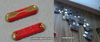
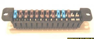
Mounting block of fuses and relays VAZ 2109
| This page presents two types of fuse and relay blocks: with finger fuses (old mounting block), with blade fuses (new type mounting block). The location of the fuse box is shown. A table has been posted with a breakdown of each fuse and relay indicating the electrical circuits they protect. There are two electrical diagrams of the internal connections of the fuse mounting blocks. Two diagrams of pinout of connecting sockets of electrical wire blocks are presented. The sequence of dismantling the fuse mounting block of a VAZ 2109 passenger car is described. |
Removal and replacement process
Required tool:
- large and small plastic tweezers (located in the main interior mounting block) or pliers with thin jaws;
- screwdrivers - slotted, Phillips;
- 8mm wrench.
Under the hood
The procedure is as follows:
- Immobilize the vehicle with the parking brake and turn off the ignition.
- Open the hood.
- Remove the cover from the desired unit by prying the plastic latches with a flat-head screwdriver.
- Remove the broken element using pliers or tweezers. Large tweezers are for removing relays, small ones are for fuses.
- Correct the problem if possible.
- Install a new part and check the operation of the protected unit.
- Reinstall the removed parts.