This article discusses the fuse and relay diagrams of the Mazda 3 bk (Mazda 3bk) first generation, from the Japanese concern Mazda Motor Corporation, produced in 2003, 2004, 2005, 2006, 2007, 2008 and 2009 with engines of 1.4 liters, 1.6 liters . and 2.0 l.
Interesting fact: in its homeland (Japan) this model is called Mazda Axela.
During this time, the sedan and hatchback managed to undergo restyling.
The location and decoding of fuse and relay blocks may differ from that discussed below, depending on the configuration and modification, as well as the year of manufacture, of your Mazda 3 bk.
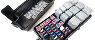
This vehicle is equipped with 2 main fuse and relay mounting blocks located in the passenger compartment and under the hood.
Fuses and relays in the cabin
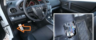
The Mazda 3 bk interior mounting block of fuses and relays is located under the glove compartment on the passenger side.
Most fuses are located in this block.
In order to get to the cabin fuses and relays, you must:
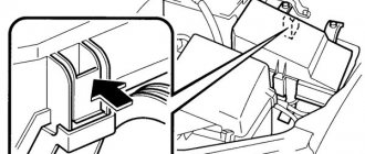
- Pull out the plastic clip from the right protective cover in the passenger footwell and move it to the side;
- Remove the protective plastic fuse cover by pressing out the two plastic clips located on both sides of the protective cover;
- Next, you need to rotate both fasteners (on both sides) by 90%, which hold the mounting block;
- Now the block can be lowered down and pushed forward a little for the convenience of replacing fuses and relays, thanks to special bracket holders.
General view of the Mazda 3 bk interior fuse box
Diagram of fuses and relays in the Mazda 3 bk interior
| No. on the diagram | Fuse rating | Protected circuit |
| 37 | 15 A | Central locking (D/LOCK 2) |
| 38 | Empty or 10A (on later models; depending on configuration) | Empty (Reserve); On later models - STOP LAMP Fuse, Horn (STOP LAMP/HORN) |
| 39 | 10 A | High beam (Left headlight) (HEAD HIGH L) |
| 40 | 10 A | High beam (Right headlight) (HEAD HIGH R) |
| 41 | — | Empty (Reserved) |
| 42 | — | Empty (Reserved) |
| 43 | 15 A | Cigarette lighter Mazda 3 (Lighter/Cigar) |
| 44 | 7.5 A | Stereo, Audio system, Radio (RADIO) |
| 45 | 10 A | Electric adjustment of side rear view mirrors (Mirror) |
| 46 | 7.5 A | Dimensions (Right side front and rear marker lights), Number plate (registration plate) illumination (TAIL R) |
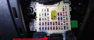
| 47 | 10 A | Diagnostic connector (OBD) |
| 48 | — | Empty (Reserved) |
| 49 | 20 A | Ignition switch circuit (TR/Lock) |
| 50 | 10 A | Electronic control unit for electrical equipment (CPU PWR, microcomputer start) |
| 51 | 15 A | Hazard lights (hazard warning lights) and turn signals (direction indicators) (HAZARDs) |
| 52 | 20 A | Sunroof (its electric drive) (SUN ROOF) |
| 53 | 20 A | Front windshield washers (WASHER) |
| 54 | — | Empty (Reserved) |
| 55 | 30 A | Power windows on the right side (front and rear) (P/WIND R) |
| 56 | 30 A | Window lifters on the left side (front and rear) (P/WIND L) |
| 57 | 7.5 A | Security alarm (ALARM) |
| 58 | 7.5 A | Heated exterior mirrors (electrically heated windows) (M/DEF) |
| 59 | — | Empty (Reserved) |
| 60 | 15 A | Low beam (Right headlight) (HEAD LOW R), lamp adjustment |
| 61 | 15 A | Low beam (Left headlight) (HEAD LOW L), lamp adjustment |
| 62 | — | Empty (Reserved) |
| 63 | — | Empty (Reserved) |
| 64 | — | Empty (Reserved) |
| 65 | 10 A | Airbag system (SRS Airbag) |
| 66 | 10 A | Immobilizer (anti-theft system), Instrument panel/instrumentation, ignition key interlock system (METER) |
| 67 | 20 A | Anti-lock braking system (ABS), directional stability control (DSC), power steering and electric pump (EHPAS), (IGNITION) |
| 68 | 20 A | Wipers (windshield wipers) (WIPER) |
| 69 | 20 A | Electronic engine management system (ENGINE) |
| 70 | 10 A | Egnition lock; Automatic wiper (IG SIG) (some models) |
| 71 | 7.5 A | Airbag system (SRS 2) |
| 72 | — | Empty (Reserved) |
| 73 | — | Empty (Reserved) |
| 74 | 20 A | Heated seats (heating) (SEAT WARM) |
| 75 | 25 A | Central locking (D/LOCK 1) |
| 76 | 10 A | Air conditioning, air conditioning compressor clutch, (A/C) |
| 77 | 30 A | Front right window regulator P/WIND R |
| 78 | 30 A | Front left window regulator P/WIND L |
| 79 | 10 A | Reversing lights (lamp lights when moving backwards) (BACK) |
| 80 | 7.5 A | Sunroof (electric) (SUN ROOF) |
| 81 | 7.5 A | Tail light (left), front marker light (left) (TAIL L) |
| 82 | 7.5 A | Fog lights (fog lights), instrument panel and control module lighting/illuminations (ILLUMI) |
| 83 | — | Empty (Reserved) |
| 84 | — | Empty (Reserved) |
| 85 | — | Empty (Reserved) |
| 86 | — | Empty (Reserved) |
The cigarette lighter fuse is number 43 with a current of 15 Amps. Depending on the modification of the car, there may be other problems; we also recommend checking number 28 for 10 Amperes under the hood.
Relay box in the cabin
You can get to the main relay blocks/sensors in the Mazda 3 bk interior after you completely remove and disconnect from the plugs that fit it, the interior mounting block with fuses and open (unscrew) the white plastic case protecting the main board where the relays are located.
Remove the fuse and relay mounting block
The protective casing was removed. Assembly block disassembled.
The relay circuit is shown in the figure above along with the fuses. Explanation in the table below.
| No. on the diagram | Protected circuit |
| R11 | Relay for reduced (first) speed of front wipers (windshield wiper) |
| R12 | Relay for the second speed of the front wipers (windshield wipers) |
| R13 | High beam headlight relay unit |
| R14 | Relay for turning on side lights/lanterns |
| R15 | Empty (Reserved) |
| R16 | Empty (Reserved) |
| R17 | Relay for blocking the central locking drives (closing the lock) |
| R18 | Relay for unlocking the central locking drives (opening the lock) |
| R19 | Relay for turning on the rear wiper (wiper), if equipped |
| R20 | Empty (Reserved) |
The video below clearly demonstrates the location of the relays responsible for the wipers and the removal of the mounting block where they are located.
Correct replacement of fuse links
Before replacing the Mazda 3 BC fuse, it is necessary to identify and eliminate the cause of the blown fusible link. To do this, the equipment corresponding to the protection zone is checked.
It is strictly forbidden to use various jumpers and fuse-links with a different rated current. This may cause electrical appliances to fail or catch fire.
The procedure for changing fusible links and relays of a Mazda 3 BK in the interior and engine compartment:
Initially, the protective casing is removed from the mounting blocks. Performing this procedure for blocks is described previously;
(Link to photo source)
Using tweezers, the damaged element is pulled out of the plastic. As a rule, the rupture of a burnt-out insert is visible visually after removal from the contact part. If the power fuses in the Mazda 3 BC block under the hood are damaged, you should remove the casing by pulling it up. In this case, the resistance of the plastic clamps is overcome.
Next, the two nuts securing the fuse-link are unscrewed and it is removed. If it is necessary to change the relay, then it must be slowly loosened from side to side and pulled out;
Then a spare protective element of the electrical circuit with similar current characteristics is installed.
On the back side of the Mazda 3 BK power unit casing there is a diagram of the location of fusible links and relays. There are also compartments for spare fuses and tweezers.
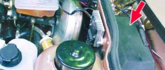
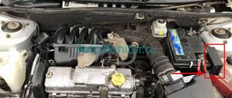
Fuses and relays under the hood
In the engine compartment, the fuse and relay box is located next to the battery.
In order to get to the “under-hood” fuses and relays, you need to remove the protective plastic cover by pulling the latch on the side of the mounting block and move it to the side.
General view of the block under the hood of Mazda 3 bk
Fuse and relay diagram in the engine compartment
| № | Denomination | Protected circuit |
| 1 | 40 A | Cooling fan (radiator) (FAN) |
| 2 | 80 A | Electric power steering pump (P/ST - EHPAS) |
| 3 | 40 A | Connector for diagnostics, Hazard warning lights, Front wipers, front windshield washers, central locking, dimensions (BTN) |
| 4 | 40 A | Headlights (HEAD) |
| 5 | 80 A | PTC circuit (EPVA, cabin air heater) (On some models) |
| 6 | (Blank) or 60 A | Empty (Reserve); in later models - 60 A glow plugs (GLOW) |
| 7 | 30 A | Brake system (ABS, abs), directional stability system (DSC) (anti-skid); [ABS1] |
| 8 | 20 A | Brake system (ABS, abs), directional stability system (DSC) (anti-skid); [ABS2] |
| 9 | 30 A | Electronic Engine Control Relay |
| 10 | — | Empty (Reserved) |
| 11 | 30 A | Ignition switch (lock) (electrical consumer circuits activated when the ignition is started and not turned off when the starter is turned on) (IG KEY1) |
| 12 | 20 A | Starter solenoid relay (clutch) |
| 13 | 30 A | Ignition switch (lock) (electrical consumer circuits activated when the ignition is started and turned off when the starter is turned on) (IG KEY2) |
| 14 | 30 A | Glow plugs (some models) (GLOW1) |
| 15 | 40 A | Heater (cabin fan) (HEATER) |
| 16 | 30 A | Glow plugs (some models) (GLOW2) |
| 17 | 40 A | Heated / Heated rear window (electric) (DEFOG) |
| 18 | 30 A | Empty (reserve); or -Audio system (for models equipped with a BOSE audio system) (AUDIO) |
| 19 | 10 A | ABS brake system (ABS), directional (anti-skid) stability system (DSC); |
| 20 | 15 A | Front fog lights (fog lights) (FOG) |
| 21 | 15 A | Sound signal (horn, horn) (HORN) |
| 22 | 10 A | Daytime running lights (DRL) on some models |
| 23 | 20 A | Headlight washers (H/CLEAN) |
| 24 | 15 A | Fuel pump (fuel pump) (F/PUMP) |
| 25 | 10 A | (Power steering) Power steering (on some models) (P/ST IG) |
| 26 | 10 A | Air Conditioning Compressor Electromagnetic Clutch (A/C MAG) |
| 27 | 10 A | Generator (ALT/TCM 1GA) |
| 28 | 10 A | Cigarette lighter (GLOWSIG) |
| 29 | 10 A | Power supply for additional car sockets (P.OUTLET) |
| 30 | 10 A | Engine control unit PCM, control unit for dosing and supply of fuel additive (ENG+B) |
| 31 | 15 A | Instrument cluster: Interior lighting lamps (interior lights, lampshades) (ROOM); RADIO (Audio system) |
| 32 | 10 A | Oxygen concentration sensor (ENG BAR 4) |
| 33 | 10 A | Oxygen concentration sensor (ENG BAR 3) |
| 34 | 10 A | Injector pre-body, injector (EGI INJ) |
| 35 | 10 A | Mass Air Flow Sensor (MAF) Fuse (ENG BAR 1) |
| 36 | 10 A | (USR) Exhaust gas recirculation system, valve (ENG BAR 2) |
Relay under the hood
| No. on the diagram | Protected circuit |
| R1 | Fog lamp relay (fog lights) FOG |
| R2 | Horn Relay (HORN) |
| R3 | Heated/defogged rear windshield (DEFOG) relay |
| R4 | ETV circuit relay |
| R5 | Fuel heating relay for diesel models (F/WARM) |
| R6 | Fuel pump relay (CIRCUIT) |
| R7 | Empty (Reserved) |
| R8 | Empty (Reserved) |
| R9 | Headlight washer relay (H/CLEAN) |
| R10 | Climate control fan relay (heater) (HEATER) |
| R11 | Air Conditioning Relay (clutch, compressor) (A/C) |
| R12 | Empty (Reserved) |
| R13 | Starter relay (retractor) (STARTER) |
| R14 | Electronic engine control unit (MAIN) |
Recommendations for servicing the mounting block
- Periodically check the condition of the fuses, replace with new ones as necessary;
- After long trips through puddles or in the rain, check for moisture and condensation in the mounting block. Dry the board with a stream of compressed air;
- Install modules with similar current strength (amperage). Do not exceed (underestimate) Amperes;
- If the mechanism suddenly stops functioning, do not rush to replace it with a new one. Check the module status, use a multimeter to diagnose;
- During preventive maintenance, check the quality of fixation of terminals and limit switches. Press with pliers as needed.
Despite the apparent simplicity of the design of the mounting block, carry out diagnostic work at a service station. Unprofessional intervention in repairs leads to undesirable consequences.