Muffler resonator - part of the exhaust system, the tasks of which include damping low-frequency sounds arising from engine operation. It will be useful for every car enthusiast to know where the resonator is located and what possible problems he will have to face during its service. A breakdown of the exhaust pipe resonator is not critical, but it can cause a lot of inconvenience not only to the driver, but also to those around him. About how to eliminate problems that have arisen, how to dismantle and install the unit, as well as how to make a resonator with your own hands — we will talk about all this in this material.
Purpose of the resonator
First, let's figure out what a resonator is for . As mentioned above, it is part of the exhaust system of a car engine. Its main function is to dampen low-frequency sounds that arise during the exhaust process of gases and their entry into the gas exhaust system. There are two reasons why noise occurs in it:
- sound from expansion of gases;
- noise from vibration of exhaust system elements.
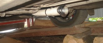
Resonator location
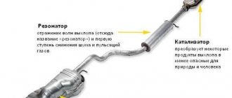
Along with a muffler, the tasks of a car resonator include reducing the speed of movement of exhaust gases. This becomes possible thanks to a physical law, according to which gases that move quickly in a narrow pipe, when they enter a large volume, lose their speed and, accordingly, energy. In the gas exhaust system, the resonator is located in front of the main muffler, being, in fact, the first link in the sound muffling chain of the exhaust system. That is, its main tasks are preliminary noise reduction and balancing of exhaust gas flow pulsations.
Some car owners call it the “middle muffler” (due to its physical location approximately in the middle of the bottom of the car) or the “second muffler.” However, this is not true because the exhaust system resonator and muffler have different operating principles.
The resonator of the car exhaust system also performs the function of freeing the engine exhaust from exhaust gases and creating uniform pressure in it. This ensures minimal resistance to the movement of exhaust gases, and it is possible to use almost all the useful engine power.
Since the resonator still takes away part of the power 10...15%, in sports cars they use so-called direct-flow mufflers and do not install resonators.
Classification
The theory of damping of resonant processes is used in design development. In practice, ready-made solutions are classified, they are already listed, the result can be summarized in a short list:
- direct-flow and multi-chamber devices;
- vibration damping by storing energy in cavities and chambers or using high-speed fiber dampers;
- the use of expensive or cheap materials, in the latter case the device becomes a consumable.
Usually it is not possible to successfully use a part from another car or a universal one; it must be selected according to its properties specifically for a specific engine.
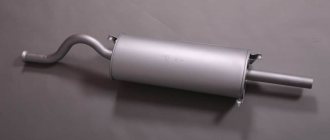
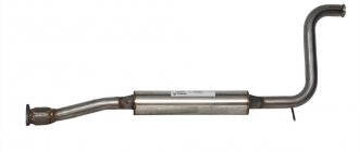
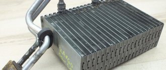
Resonator device
Structurally, the resonator consists of a perforated (drilled along the entire length within the device) pipe placed in a metal casing. The design also has a throttle hole designed to increase the efficiency of damping wave vibrations in the pipe. The internal cavity of the resonator is divided into two or more unequal parts by partitions located in a transverse plane to the pipe. Also, more modern exhaust resonators are designed with thermal insulation and/or sound insulation (often the same material) located under the housing and designed to reduce its temperature and/or sounds emanating from the device.
Internal structure of the resonator
The internal cavities have an unequal volume in order to ensure periodic narrowing and expansion of the flow of exhaust gases, which in turn equalizes their uneven pulsation. That is, each chamber has its own resonant frequency. In addition, they have a slight offset relative to the axis of the body. This is necessary to achieve a change in the direction of the exhaust flow. And internal perforation on the pipe is needed to dampen the large amplitude of sound waves that produce gases.
The efficiency of the resonator is influenced by the following factors:
- the degree of its wear, tightness;
- level of contamination from soot (the cleaner, the more effective);
- diameter (the larger the diameter of the device, the greater its efficiency).
Repair
Chassis device Anti-roll bar Anti-roll bar Self-propelled chassis Self-propelled chassis Car chassis device, purpose Car chassis device, purpose Car chassis device Chassis device The
muffler resonator is subject to repair only if holes form in it. For this you will need:
- piece of tin;
- metal screws for attaching a tin “patch”;
- sandpaper;
- drill and metal drill bit;
- putty and hardener.
The operating procedure is as follows:
- Cut a plate from tin that is larger in size than the damage that is supposed to be repaired.
- Clean the surface on which the patch will be installed.
- Drill several holes in the body and plate.
- Using putty and hardener, install the plate in place.
- Secure the patch using self-tapping screws.
- You can start operating the car after the putty has hardened.
Problems with the resonator
Like any part, a car resonator periodically fails. After all, it passes through exhaust gases having a temperature of several hundred degrees Celsius. And in combination with the aggressive chemical elements contained in the escaping gas mixture, this leads to gradual burning of the metal parts of the system.
The main signs of resonator failure are:
- Deterioration of the muffler and exhaust system . This is manifested by increased sound coming from the exhaust pipe, especially low frequency sounds (roar).
- The appearance of exhaust gases from under the bottom of the car . This is a clear sign of depressurization of the resonator or other parts of the gas exhaust system.
- The presence of a characteristic rattling metallic sound from the resonator . It appears due to the fact that one (or more) of the internal components of the device burns out. Usually in such cases he “hangs out” or breaks away and rumbles in one of the cells.
- Significant drop in engine power . Due to a malfunction, the throughput of the resonator decreases significantly, so it dampens uneven pulsations of exhaust gases worse or not at all. And this gives feedback on the deterioration of the power unit.
If you encounter one or more of the above signs of a resonator malfunction, you need to inspect its operation as quickly as possible
How to check the catalyst?
Engine power depends on the condition of the catalyst. If there are characteristic symptoms of a breakdown, you should definitely check it. This can be done in light (by dismantling) and for back pressure or CO content without removing Read more
Shoots the silencer
Does your car engine need to shoot at the muffler? Then it’s worth checking the ignition system, fuel supply or timing marks. Find out the reasons and how to get rid of popping sounds from the muffler Read more
Replacing the VAZ 2110 resonator
Repairing the exhaust system or replacing the muffler on a VAZ 2110 most often involves replacing the resonator, since welding does not take long to solve the problem of burnout. The main task is to quickly remove the resonator Read more
What is it for?
In a system that ensures the removal of burnt gases, the resonator ensures the timely removal of the gaseous mixture from the motor chamber.
A significant part of automotive specialists are confident that the level of useful power provided by the power unit largely depends on the quality of this part.
That is why sports cars are always amenable to modernization: the standard model of the resonator, which is included in the basic package, is replaced with a more advanced version.
In order for the main flow of the exhaust mixture from the engine to fall directly on this part, it is placed immediately behind the forward flow. As a result of this, the better quality and functionality the spare part is, the higher the overall driving performance of the vehicle will be.
In addition, the presence of such a spare part significantly reduces the level of emissions of harmful gases into the environment.
Checking the resonator
When identifying the problems listed above, every motorist should know how to check the resonator . This will not only normalize the operation of the engine and exhaust system, but also increase the comfort of using the car, including for the people around you.
To check, you will need an inspection hole (if you don’t have one, you can jack up the car). Diagnosis is made using visual inspection. During the process, it is necessary to carefully examine the integrity of both the device itself and the pipes connected to it (especially at their joints).
When working in an inspection pit and when lifting the machine on a jack, always be careful and follow safety rules.
A clear sign of a problem is the formation of condensation in the cooling resonator, after which it begins to drip to the ground. This means that its body has lost its tightness and must be repaired, or better yet, replaced. You can check for condensation after some time, when you turn off the engine (to allow the resonator body to cool). Note! Some car enthusiasts, when making resonators on their own, specially drill a hole in its body to remove moisture . Therefore, if you bought a car with a similar resonator, then this testing method will not work for you.
Damaged resonator
Also, the integrity of the resonator body can be determined by the presence of exhaust gases leaving it. This also indicates depressurization and the need to replace it. This fact can be checked with the car engine running by looking under the bottom. To be sure, you can ask an assistant to “turn on the gas” at the same time so that more exhaust gases pass through the system. Also, suspicion of depressurization is caused by the appearance of smoke from under the bottom of the car while driving or when parked with the engine running.
As practice shows, it is better not to repair the resonator, but to replace it. This is especially true for cars with significant mileage (more than 100 thousand kilometers).
Typical faults
There is one reason why a car muffler fails - prolonged exposure to high-temperature exhaust gases. Sooner or later, the metal body of the element burns out, which is accompanied by a rumble under the bottom of the car (from where the faulty part is located).
The service life of a muffler greatly depends on the material from which it is made:
- ordinary “black” metal with a special coating;
- stainless steel.
A cheaper option, made from “black” rolled metal, can burn out after 20–30 thousand km, while a stainless steel body will last 100 thousand km or more. Another thing is that over a long period of time the insides of the muffler can burn out and the noise level will increase noticeably.
Malfunctions can be eliminated in two ways: replacing the muffler and repairing by welding. In any case, you will have to visit a car service center, where, after diagnostics, the technicians will help you make the right decision. If the opening of the fistula is small, then an experienced specialist will weld it directly on the machine. The second option is to apply a metal patch, for which the muffler will need to be removed. An element with burnt-out internals cannot be repaired, only replaced.
Types of automotive resonators
When choosing an exhaust system resonator, you need to know what types they are and what materials they are made from. Currently, automotive resonators made of aluminized steel and stainless steel . The former are distinguished by their low price, but short service life. Their body is made of thin steel, coated with aluminum on top to prevent corrosion. However, this anti-corrosion composition is not durable. Therefore, we do not recommend that you buy an exhaust resonator made of aluminized steel. It is better to buy a car resonator made of stainless steel. This material has a smoother surface (that is, creates a minimum of turbulence in the system), and is also more resistant when working under extreme temperatures.
Crystal oscillator
What is a generator? A generator is essentially a device that converts one type of energy into another. In electronics, you can often hear the phrase “electric energy generator, frequency generator, function generator,” etc.
A crystal oscillator is a frequency generator and contains a quartz resonator. Basically, crystal oscillators come in two types:
those that can produce a sine wave signal
and those that produce a square wave signal, which is most often used in digital electronics.
Pierce's scheme
In order to excite quartz at the resonance frequency, we need to assemble a circuit. The simplest circuit for exciting quartz is a classic Pierce oscillator , which consists of just one field-effect transistor and a small circuit of four radio elements:
pierce circuit for a quartz resonator
A few words about how the scheme works. There is positive feedback in the circuit and self-oscillations begin to appear in it. But what is positive feedback?
At school, all of you were vaccinated for the Mantoux test to determine if you had a tube or not. After some time, nurses came and used a ruler to measure your skin reaction to this vaccination.
When this vaccination was given, it was forbidden to scratch the injection site. But I, then still a new guy, didn’t give a damn. As soon as I began to quietly scratch the injection site, I wanted to scratch even more)) And so the speed of the hand that was scratching the vaccine froze at some peak, because I could oscillate my hand at a maximum frequency of 15 Hertz. Vaccination my arms swelled up to the floor)) And even once they took me to donate blood on suspicion of tuberculosis, but as it turned out, they didn’t find it. It's not surprising ;-).
So why am I telling you jokes from life here? The fact is that this scabies vaccination is the most positive feedback there is. That is, as long as I didn’t touch it, I didn’t want to scratch it. But as soon as I scratched it quietly, it began to itch more and I began to scratch more, and it began to itch even more, and so on. If there were no physical restrictions on my arm, then for sure the vaccination site would have already been worn down to the flesh. But I could only wave my hand with a certain maximum frequency. So, the same principle applies to a quartz oscillator ;-). Give a little impulse, and it starts to accelerate and stops only at the parallel resonance frequency ;-). Let's call it "physical limitation".
First of all, we need to select an inductor. I took a toroidal core and wound several turns from MGTF wire
toroidal inductor
The whole process was controlled using an LC meter, achieving a nominal value as in the diagram - 2.5 mH. If it wasn’t enough, he added more turns; if he overdid it, then he decreased it. As a result, I achieved this inductance.
inductance measurement
I didn’t find the transistor in my stash, and the local radio store didn’t have it either. Therefore, I had to order from Ali. If anyone is interested, I got it here.
Its correct name is a field-effect transistor with an N-type channel.
transistor 2n5485 Pinout from left to right: Drain - Source - Gate
Well, then it’s a matter of little things. Let's assemble the circuit:
A small lyrical digression.
As you can see, I tried to reduce connections between radio elements as much as possible. The point is that all radioelements have their own parasitic parameters. The longer their leads, as well as the wires connecting these radio elements in the circuit, the worse the circuit will work, or even not work at all. And in general, circuits with a quartz resonator on printed circuit boards are traced for a reason. There are subtle nuances here. The smallest parasitic parameters can spoil the entire signal at the output of such a generator.
So, we have assembled the quartz oscillator, applied the voltage, all that remains is to remove the signal from the output of our homemade generator. The OWON SDS6062 digital oscilloscope gets down to business
First of all, I took the quartz to the highest frequency that I have: 32,768 Megahertz. Do not confuse it with watch quartz (which will be discussed below).
No, but what did you want? Did you want to see an ideal sine wave? Not so. The parasitic parameters of the poorly assembled circuit and installation had an effect.
At the bottom left corner the oscilloscope shows us the frequency:
As you can see 32.77 Megahertz. The main thing is that our quartz is alive and the circuit works!
Let's take a 27 MHz crystal.
The frequency was also shown more or less correctly.
Well, we check all the other quartz that I have in the same way.
Here is an oscillogram of quartz at 16 MHz.
The oscilloscope showed a frequency of exactly 16 MHz.
Here I installed quartz at 6 MHz.
Exactly 6 MHz!
At 4 MHz.
All OK.
Well, let’s take another Soviet one at 1 Megahertz. This is what he looks like.
At the top it says 1000 KHz = 1 MHz.
Let's look at the oscillogram.
Worker!
If you really want, you can even measure the frequency with a Chinese generator-frequency meter.
frequency measurement with a frequency meter
400 Hertz error is not very much for an old Soviet quartz, although the problem may not even be with the quartz, but with the frequency meter itself.
Pierce circuit for square wave
So, let's return to Peirce's scheme. The previous Pierce circuit generates a sinusoidal signal
But there is also a modified Pierce circuit for a square wave
And here she is:
Peirce's scheme for a meander
The values of some radioelements can be changed in a fairly wide range. For example, capacitors C1 and C2 can be in the range from 10 to 100 pF. The rule here is this: the lower the quartz frequency, the smaller the capacitance of the capacitor should be. For watch crystals, capacitors can be supplied with a nominal value of 15-18 pF. If the quartz has a frequency of 1 to 10 Megahertz, then you can set it to 22-56 pF. If you don’t want to bother, then just install capacitors with a capacity of 22 pF. You really can't go wrong.
Also a small tip to note: by changing the value of capacitor C1, you can adjust the resonance frequency within very fine limits.
Resistor R1 can be changed from 1 to 20 MOhm, and R2 from zero to 100 kOhm. There is also a rule here: the lower the quartz frequency, the greater the value of these resistors and vice versa.
The maximum crystal frequency that can be inserted into the circuit depends on the speed of the CMOS inverter. I took the 74HC04 chip. It's not very fast-acting. It consists of six inverters, but we will only use one inverter.
Here is its pinout:
Having connected a clock quartz to this circuit, the oscilloscope produced the following oscillogram:
Well, as always, the whole picture was spoiled by parasitic editing parameters. But, pay attention to the frequency. The oscilloscope showed it almost correctly with a small error. Well, this is understandable, since the main function of an oscilloscope is to display the signal, and not to count the frequency)
By the way, does this part of the diagram remind you of anything?
Isn't this part of the circuit used to clock microcontrollers?
She's the one! It’s just that the missing elements of the circuit are already in the MK itself
Colpitts scheme
This is also a fairly common and famous scheme.
Colpitts circuit
Take as a basis an amplifier circuit with a common collector (emitter follower). Everything is as usual here. Resistors R1 and R2 set the operating point for the transistor. Resistor RE sets the output voltage level. The NPN 2N4265 transistor can operate at frequencies up to 100 MHz, which is why we took it. This circuit will work with crystals in the range from 1 to 5 MHz.
Ready-made crystal oscillator modules
Currently, quartz oscillators are produced in the form of complete modules. Some companies producing such generators achieve frequency stability of up to 10-11 from the nominal value! The finished modules look something like this:
types of crystal oscillators
or so
Such crystal oscillator modules mainly have 4 outputs. Here is the pinout of a square crystal oscillator:
crystal oscillator pinout
Let's check one of them. It says 1 MHz
1 MHz crystal oscillator
Here's his rear view.
By applying a constant voltage from 3.3 to 5 Volts with a plus of 8 and a minus of 4, from output 5 I got a clean, smooth, beautiful square wave with a frequency written on a quartz oscillator, that is, 1 Megahertz, with very small emissions.
signal from a crystal oscillator
Well, you can really admire it).
And the Chinese generator-frequency meter showed the exact frequency.
From here we conclude: it is better to buy a ready-made quartz oscillator than to waste a lot of time and nerves on setting up a Pierce or Colpitts circuit. Pierce's circuit will be suitable for testing resonators and for your various homemade products, although on Aliexpress I came across a ready-made quartz resonator tester capable of measuring quartz frequencies from 1 to 50 MHz. You can look at this link.
DIY resonator
Before designing and assembling a resonator of your own design, you need to understand one simple thing. The thicker the material from which the exhaust system is made (including the resonator), the more effective the fight against vibrations and resulting noise will be. It is for this reason that the exhaust manifold, which is the first to receive gases from the cylinder head, has such an impressive weight.
Elements of the exhaust system of foreign cars have greater mass than those of domestic cars. Accordingly, they are quieter and more comfortable.
However, when choosing a material, you should not overdo it and choose too massive blanks. Otherwise, the mass of the resonator will be significant, and this will affect the dynamic characteristics of the car and the load on its chassis.
There are a number of reasons why car owners make their own exhaust resonators. One of them is to reduce the noise that a standard factory muffler produces. Usually, for this purpose, an additional resonator is installed in the exhaust system. The second reason is the manufacture and installation of a direct-flow car resonator . Its features are as follows:
Homemade resonator
- reduction in engine power loss (actually insignificant, about 5...10%);
- changing the sound background of the engine and exhaust system (for lovers of low sound).
To make a direct-flow resonator you will need:
- a set of locksmith tools;
- welding machine (it is advisable to use modern semi-automatic machines or inverters);
- angle grinder with a set of cutting and grinding discs.
The design of the resonator will differ depending on the materials used and the imagination of the car owner. We offer you one of the options for self-manufacturing a direct-flow automotive resonator :
- Pre-prepare the pipe that will serve as the internal base of the resonator. It should be the same or slightly larger diameter than the factory one. Make sure that it can be easily welded to the existing system in the future, so do not choose a diameter that is too large (unless it is possible to connect the pipe using a flange).
- Next, you need to drill holes in this pipe, similar to the stock resonator.
- After this, you need to find a pipe with a slightly larger diameter (about 3...5 cm), which will serve as the outer casing. Its length needs to be made smaller (depending on the design, on average by 5...10 cm on each side).
- The plugs necessary to seal the housing at the ends are made. For this, sheet metal is used, where the outer diameters of the large and small pipes are drawn. Afterwards, the blanks are cut out and processed using a grinding machine.
- A pipe with a larger diameter is placed on a pipe with a smaller diameter, and the cavity between them is filled with glass wool (or better yet, modern mineral wool with good heat and sound insulation characteristics).
- Next, you need to weld the ends around the edges of the pipe with a large diameter using pre-made plugs.
- After welding work, clean the seams using an angle grinder. After this you should paint them.
- The last stage is welding the new resonator into the car's exhaust system. After carrying out the work, also clean the welding seams.
DIY resonator
The given algorithm is approximate . There are a wide variety of options for homemade resonators. In some cases, they are simply thrown out of the system, replacing them with a piece of pipe. However, we do not advise you to do this, since you will not receive a significant addition to the car’s power, but an additional roar from the exhaust pipe is guaranteed!
Additional problems
After installing a self-made resonator, the car owner will likely encounter a number of problems that must be solved. First of all, we are talking about increasing the mass of the gas exhaust system, and, accordingly, the car as a whole. This is true if you used heavy metal elements to make the resonator. Therefore, a situation may arise when it is necessary to replace the brackets and/or shock absorbers. That is, strengthen them. Otherwise, the car body will “sag”, and the chassis will experience additional load.
In addition, replacing the resonator entails a change in the ratio of air entering the engine and the amount of exhaust gases. Therefore, it is necessary to empirically determine which optimal settings to choose and make appropriate adjustments in fuel supply and air filtration.
An exhaust manifold
For the muffler to work, it must be connected to the engine. Moreover, the connection must be made exactly in the place where the exhaust gases are released at the end of the next power stroke.
This important function is performed by a part called the exhaust manifold. People often call this element “pants” for its specific shape and design. At its core, the exhaust manifold is a metal tube with thick walls, which is gradually divided into several others and tightly connected to the cylinder head. Through these several branches, the exhaust gases from each cylinder are collected together, from where they are centralized into a combining tube and sent towards the rear half of the housing.
The wall thickness and material of manufacture were also not chosen by chance. It is worth considering that exhaust gases come from the engine heated to extremely high temperatures. It is for this purpose that cast iron was chosen as the manufacturing material, and the wall thickness was made as wide as possible. This allows you to avoid excessive expansion of the metal and its cracking during operation.
Removing and installing the resonator
Many motorists are interested in a natural question - how to remove the resonator ? The answer to this question will vary depending on the brand of car. However, in general, the algorithm is simple and will be approximately as follows:
- it is necessary to disconnect the resonator pipes at the points of their connection with the exhaust gas removal system (front, on the engine or catalyst side, and at the rear, on the muffler side);
- remove the resonator from its suspensions, with the help of which it is attached to the bottom of the car;
- dismantle the resonator with its pipes.
How to replace a Renault Logan resonator
Installing a new device is done in the reverse order. When removing the resonator, it is important not to damage the O-rings that connect its pipes to the rest of the exhaust system.
As an example, we present to your attention two video instructions demonstrating the replacement of the resonator on popular Renault Logan cars and front-wheel drive VAZ 2110, VAZ 2111, VAZ 2112, VAZ 2114, VAZ 2115, Kalina, Priore, Grante.
Finally
Partial or complete failure of the car exhaust system resonator is not a critical failure . Diagnosing a resonator failure is not difficult even for an inexperienced car owner. This is indicated by a loss of power, the spread of exhaust gases under the bottom and/or into the cabin, and an increase in background noise when the engine is running. Please note that the car can be used case, however, we still recommend that you do not delay repairs, since driving with a burnt-out resonator can lead to failure of other elements of the vehicle’s exhaust system.
General meaning
Mitsubishi Galant American, AT Logbook Replacing the muffler pipe gasket Fa1 740-908
Those who conceived and invented the first cars used mufflers of the so-called direct-flow operating principle.
Over time, such exhaust systems began to become a thing of the past, and leading American and European manufacturers came up with a more complex mechanism. Unlike direct-flow exhaust, it made it possible not only to reduce the noise level that the engine produced during operation, but also to reduce the toxicity of gases emitted into the atmosphere.
In general terms, the operation scheme of a modern exhaust system is much more complex than in the case of the direct-flow type, and therefore has several working elements at once, each of which, in turn, has a rather complex design. Their constant interaction makes it possible to significantly reduce noise, increase environmental friendliness and even reduce fuel consumption, which especially significantly affects the owners’ wallets and their desire to own a particular passenger car in the future.