The 5th Volkswagen Golf was produced in 2003, 2004, 2005, 2006, 2007, 2008 and 2009, mainly in a hatchback body, with both gasoline and diesel engines. In our material you will find a description of the fuse and relay blocks of the Volkswagen Golf 5 with diagrams and photographs. We will show you the location of all electronic control units. Separately, we note the fuse responsible for the cigarette lighter. This material will also be useful to the owner of a Volkswagen Jetta 5, since these models have a similar electrical circuit.
Isn't it the right generation? Study the description for either accordingly.
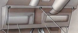
General arrangement of control units
Scheme
Designation
| 1 | Electronic air conditioning control unit |
| 2 | Air conditioner/heater fan motor control unit |
| 3 | Side impact sensor, driver's side |
| 4 | Side impact sensor, rear left |
| 5 | Side impact sensor, passenger side |
| 6 | Side impact sensor, rear right |
| 7 | Vehicle tilt sensor (anti-theft system) |
| 8 | Accumulator battery |
| 9 | Diagnostic connector (DLC) |
| 10 | Data bus connector |
| 11 | Driver's door electrical control unit - in the door |
| 12 | Left rear door electrical control unit |
| 13 | Passenger door electrical control unit - in the door |
| 14 | Right rear door electrical control unit |
| 15 | Cooling Fan Motor Control Module - On Cooling Fan Motor |
| 16 | Fuse/Relay Box, Engine Compartment 1 |
| 17 | Fuse/Relay Box, Engine Compartment 2 |
| 18 | Engine Compartment Fuse/Relay Box 3 - Under Engine Compartment Fuse/Relay Box 1 |
| 19 | Fuse/Relay Box, Instrument Panel 1 |
| 20 | Fuse/Relay Box, Instrument Panel 2 |
| 21 | Fuse/Relay Box, Instrument Panel 3 |
| 22 | Headlight range control unit (models with xenon headlights |
| 23 | Heater fan motor resistor |
| 24 | Beep 1 |
| 25 | Beep 2 |
| 28 | Instrument cluster control unit |
| 29 | Multi-function control unit 1 - in the instrument panel fuse/relay box 3-functions: Cigarette lighter, cruise control, fog lights, hazard warning lights, headlights, rear defroster, horn, interior lights, rear window wiper/washer, rear lights travel, front dimensions, brake lights, windshield washer, windshield wiper |
| 30 | Multi-function control unit 2 - functions: Anti-theft system, trunk/rear door lock, trunk/rear door opening drive, central locking, power door mirrors, power windows, fuel filler flap drive, sunroof |
| 31 | NOx sensor control unit - under the body |
| 32 | Parking system control unit - right luggage compartment |
| 33 | Power steering control unit - above the steering rack |
| 34 | Electronic control unit SRS |
| 35 | Steering column electrical control unit |
| 36 | Telephone control unit - under seat, if installed |
| 37 | Trailer electrical control unit - left luggage compartment |
| 38 | Electronic transmission control unit - behind the wheel arch |
| 39 | Windshield wiper control unit - on the intake system resonator |
Auto parts for foreign cars, auto repair
The manufacturer understands perfectly well that any car, first of all, should provide driving pleasure. That is why the sedan is equipped with an excellent line of units that are a fusion of innovative technologies and legendary German quality.
At the front, the sixth generation Volkswagen Jetta has convenient 2012 Volkswagen Jetta fuse box diagram with good lateral support, optimal rigidity padding, heating and a large set of adjustments, optionally with electric drive.
On the second row there is a well-profiled sofa and a sufficient supply of free space; however, the sedan has a high tunnel and a protruding end of the front box, which cause discomfort to the middle passenger.
The cargo compartment of the three-volume vehicle in its standard form accommodates liters of luggage and demonstrates an almost correct shape. The back of the rear sofa folds into two unequal sections but does not form a flat platform, freeing up space for transporting long items.
There is a full-size spare tire in a niche under the floor of the car. The second is 1. Both the front and rear of the car are equipped with independent suspensions with hydraulic shock absorbers and stabilizers - MacPherson-type architecture and a multi-link system, respectively.
The German sedan is equipped with a rack and pinion steering center with an electromechanical power steering.
The new Volkswagen Jetta is a full-fledged C class car, quite spacious inside and with a spacious luggage compartment. A few bright touches were added to the exterior, and it became possible to install LED rear lights.
By the way, the headlights can have halogen, bi-xenon or LED headlights. The classic exterior with smooth lines is diluted with aggressive air intakes at the bottom of the front bumper and integrated foglights. The Jetta 6 has different ratings of fuses: Where are the Jetta Fuses? The fuses on the Jetta 6 are based in two places.
The second is in the cabin, under the panel, in the area where the driver’s left knee is located. To replace, you only need tongs, which can often be found in one of the blocks.
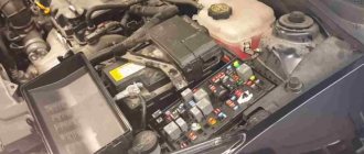
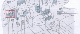
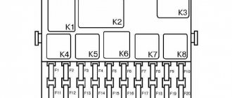
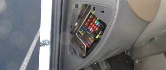
Fuse and relay box under the hood
It is located next to the battery and is covered with a protective cover. Consists of two blocks. 1 - Department of high power fuses in the form of fuse links. 2 - fuse and relay department.
Fuse and relay box
Option 1
Photo - example
Scheme
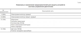
Purpose
| 1 | Engine control relay |
| 2 | Exhaust air pump relay |
| F1 | (30A) Windshield wiper |
| F2 | (5A) Steering column electrical control unit / (30A) Mechatronic unit for DSG gearbox |
| F3 | (5A) On-board power supply control unit |
| F4 | (30A) ABS electronic control unit |
| F5 | (15A) Electronic gearbox control unit |
| F6 | (5A) Instrument cluster |
| F7 | (40A) Power relay |
| F8 | (15A) Audio system / Head unit |
| F9 | (5A) Telephone control unit |
| F10 | (5A/10A) Electronic engine control unit |
| F11 | (20A) Additional heater control unit |
| F12 | (5A) CAN data bus, gateway control unit |
| F13 | (15A/30A) Electronic engine control unit |
| F14 | (20A) Engine management system, Ignition coil |
| F15 | (5A/10A) Engine management system, Lambda probe |
| F16 | (30A) ABS electronic control unit, Right headlight |
| F17 | (15A) Horn |
| F18 | (30A) Audio system |
| F19 | (30A) Windshield wiper/washer |
| F20 | (10A) Coolant pump |
| F21 | (10A/15A) Engine management system, Lambda probe, Electromagnetic clutch of supercharger drive |
| F22 | (5A) Clutch pedal limit switch (position sensor) |
| F23 | (5A/10A/15A) Engine management system, Fuel pressure regulator, Secondary air pump relay |
| F24 | (10A) Engine management system, EGR valve, Solenoid valve |
| F25 | (40A) ABS control unit |
| F26 | (30A) Left headlight |
| F27 | (50A) Glow plug control unit |
| F28 | (40A) Main ignition circuits |
| F29 | (50A) Seat position adjustment thermal fuse 1 |
| F30 | (40A) Starting system (50A) X contact relief relay |
Option 2
Photo
Scheme
Description
| 1 | Relay 2 main ignition circuits |
| 2 | Starter relay |
| 3 | Fuel pump relay - 1.4 (BCA) / 1.6 (BGU) |
| 4 | Relay 1 main ignition circuits |
| F1 | (30A) ABS |
| F2 | (30A) ABS |
| F3 | (20A) Multifunction control unit 2 |
| F4 | (5A) Multifunction control unit 1 |
| F5 | (20A) Horn |
| F6 | (5A/20A) Motor control |
| F7 | (5A) Brake light switch (brake pedal position sensor), clutch pedal position sensor |
| F8 | (10A) Cooling fan motor control unit, engine control |
| F9 | (10A) Motor control |
| F10 | (10A) Motor control |
| F11 | (25A) Engine control - petrol |
| F12 | (15A) Motor control |
| F13 | (20A) Automatic transmission |
| F14 | — |
| F15 | (40A) Starter |
| F16 | (15A) Steering column electrical control unit |
| F17 | (10A) Instrument cluster |
| F18 | — |
| F19 | (15A) Audio system, navigation system |
| F20 | (10A) Telephone |
| F21 | — |
| F22 | — |
| F23 | (10A) Cruise Control |
| F24 | (10A) Data bus connector |
| F25 | — |
| F26 | (5A) Engine Control - Diesel |
| F27 | (10A) Crankcase ventilation heater |
| F28 | (20A) Automatic transmission |
| F29 | (20A) Motor control |
| F30 | (20A) Heater/air conditioner |
| F31 | (25A) Windshield wiper |
| F32 | (10A) Motor control |
| F33 | (15A) Fuel priming pump |
| F34 | — |
| F35 | — |
| F36 | — |
| F37 | — |
| F38 | (10A) Headlight range control |
| F39 | (5A) Engine oil temperature sensor, instrument cluster |
| F40 | (20A) Instrument panel fuse/relay block 1 (F1-F11/ F29-F31) |
| F41 | — |
| F42 | (5A) Engine Control - Gasoline |
| F43 | — |
| F44 | — |
| F45 | — |
| F46 | — |
| F47 | (40A) Multifunction control unit 1 |
| F48 | (40A) Multifunction control unit 1 |
| F49 | (50A) Multifunction control unit 1 |
| F50 | (40A) Audio system |
| F51 | (50A) Glow plug control unit |
| F52 | (50A) Multifunction control unit 1 |
| F53 | (50A) Instrument panel fuse/relay block 1 (P32-B37), instrument panel fuse/relay block 2(F4) |
| F54 | — |
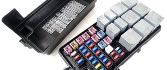
Fuse block
Option 1
Decoding
- 150A/200A – Generator
- 80A - Power steering control unit
- 50A - Radiator fan and its control unit
- 40A - Low heating power relay or Additional equipment
- 100A - Fuses in the cabin
- 80A - Fuses in the cabin, 100A - additional equipment
- 30/40/50A - Trailer connection and additional equipment
Option 2
Designation
- 150A/200A – Generator
- 80A - Power steering unit
- 50A - Radiator fan and its control unit
- 40A - Fuses in the cabin
- 100A - Fuses in the cabin, 80A - additional equipment
- 80A - Fuses in the cabin, 100A - additional equipment
- 50A - Reserve
In some models, it is possible to locate additional relays outside the unit: glow plug control relay and air supply pump relay.
Engine
Designation and where are the relays and fuses located on the Nissan Almera
Cylinder head, Valve, Valve springs, Valve rocker (rocker arm), Valve retainer, Intake valve, Exhaust valve, Hydraulic lifters, Valve seals, Valve lifter, Valve cover, Oil filler cap, Valve cover gasket, Cylinder head gasket, Camshaft, Camshaft oil seal , Camshaft gear, Intermediate shaft, Cylinder head bolt, Valve guide, Vtec valve, Vtec valve gasket, Oil pipe, Cylinder block, Crankshaft, Crankshaft pulley, Pulley bolt, Crankshaft bolt, Main bearings, Crankshaft cover (yoke), Oil deflector, Half rings , Crankshaft oil seal, Crankshaft hub, Crankshaft gear, Piston, Piston rings, Piston pin, Connecting rod, Connecting rod bolt, Connecting rod bearings, Connecting rod bushing, Engine sump, Pan gasket, Drain plug, Cylinder liner, Oil pump, Oil pump chain, Oil gasket pump, Oil receiver, Oil separator, Oil nozzle, Balance shaft, Filter housing, Engine cover, Engine timing belt, Timing belt, Timing kit, Timing belt roller, Timing tensioner, Timing tensioner roller, Timing chain, Chain kit, Chain tensioner, Chain tensioner , Phase adjuster, Timing gear, Timing belt cover, Timing cover gasket, Engine mount, Engine bracket, Engine bump stop, Engine mount (support), Engine assembly, Engine gaskets, Engine sensors, Engine oil cooler, Oil filter mount, Oil filter gasket , Engine cover, Engine protection, Engine pipe, Oil dipstick
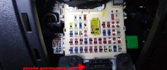
Blocks in the cabin
Fuse box
It is located at the end of the dashboard on the driver's side behind the protective cover.
Scheme with purpose
Detailed description
| F1 | (10A) Diagnostic connector DLC, Engine control unit, Relay for operation in auxiliary heater mode |
| F2 | (5A) АВS, ESP |
| F3 | (10A) Power steering, (5A) airbag control unit |
| F4 | (5A) Seat heater, heater/air conditioner, climate control unit, oil level and temperature sensor, reversing light |
| F5 | (5A) Brake light switch (brake pedal position sensor), clutch pedal position sensor, adaptive lighting and headlight range control unit, on the right headlight |
| F6 | (5A) Data bus connector, engine control, instrument cluster control unit, adaptive lighting and headlight range control unit, on the left headlight |
| F7 | (5A) Headlight range control unit, interior mirror |
| F8 | (5A) Interior rear view mirror, (10A) - Trailer control unit |
| F9 | (5A) Electronic control unit 4WD, navigation system |
| F10 | (5A) Telephone, seat occupancy detection unit |
| F11 | (5A) Trailer electrical control unit |
| F12 | (10A) Door electrical control unit (driver), door electrical control unit (passenger), central locking |
| F13 | (10A) Diagnostic connector, light switch, rain and light sensor |
| F14 | (5A) Brake light switch (brake pedal position sensor), automatic transmission control unit, ABS control unit |
| F15 | (7.5A) Multifunctional control unit (interior lighting) |
| F16 | (10A) Heater/air conditioner, antenna selection control unit |
| F17 | (5A) Audio system, rain sensor (windshield wiper), anti-theft alarm horn |
| F18 | (5A) Parking system control unit, selector lever position sensor |
| F19 | (5A) Emergency data recorder |
| F20 | (5A) Anti-lock brake system |
| F21 | (5A) Control unit for limiting maximum engine speed, in the footwell on the front left (special vehicles) |
| F22 | (40A) Supply fan |
| F23 | (30A) Power windows, door control unit |
| F24 | (25A) Cigarette lighter fuse front and rear, central control unit for comfort systems |
| F25 | (25A) Multifunctional control unit (rear window heating element, air conditioning control unit, heater and operating mode selection switch) |
| F26 | (20A) Charging connector (socket) (25A) Rear door control unit |
| F27 | (15A) Engine control (fuel pump) |
| F28 | (25A) Inverter with socket for special vehicles |
| F29 | (10A) Motor control |
| F30 | (5A) Airbag (10A) Injectors (20A) Automatic transmission control unit |
| F31 | (5A) Reversing lights (20A) Brake vacuum pump |
| F32 | (15A) Power windows |
| F33 | (25A) Hatch |
| F34 | (15A) Electric seats |
| F35 | (5A) Anti-theft system |
| F36 | (20A) Headlight washers |
| F37 | (30A) Seat heater |
| F38 | (20A) Anti-theft alarm horn relay, convenience systems central control unit |
| F39 | — |
| F40 | (40A) Heater/air conditioner |
| F41 | (15/20A) Rear window wiper/washer |
| F42 | (15/20A) Windshield washer, Cigarette lighter |
| F43 | (15A) Trailer electrical control unit |
| F44 | (20A) Trailer electrical control unit |
| F45 | (15A) Trailer electrical control unit |
| F46 | (5A) Air conditioning/heating system, heater and windshield washer nozzles |
| F47 | (5A) Heater/air conditioner |
| F48 | (7.5A) Power seats, power steering column adjustment, Charger for Mag-Lite flashlight and walkie-talkie |
| F49 | (7,5) Light switch |
Depending on the configuration and year of manufacture, fuses 24 or 42 are responsible for the cigarette lighter.
Relay block
The relay block is located under the instrument panel on the driver's side and consists of 2: main and additional.
Basic
Scheme
Designation
| 1 | — |
| 2 | Heated mirror relay |
| 3 | — |
| 4 | Multifunction control unit relay |
| 5 | Rear window defroster relay |
| 6 | Horn relay |
| 7 | Windshield washer pump relay 1 |
| 8 | Windshield washer pump relay 2 |
| 9 | Auxiliary Ignition Relay |
Additional
Scheme
Purpose
| 1 | Headlight washer pump relay |
| 2 | Fuel lift pump relay - Diesel |
| 3 | Starter relay |
| 4 | Headlight washer pump relay |
| 5a | Start relay (fuel system) |
| 5b | Auxiliary heater relay |
| A | 30A Thermal fuse 1 driver's seat adjustment |
| IN | 30A Thermal fuse 2 driver's seat adjustment |
Where is the fuse for the windshield washer?
Fuses and relays bmw e32, 1987 - 1994
Volkswagen Polo Sedan
— produced in Russia in 2010, 2011, 2012, 2013, 2014. In 2015, the car was restyled and the updated model was also produced in 2022, 2022, 2022, 2022, 2022 and to the present day. In our material we will show a description of the fuses and relays of the Volkswagen Polo Sedan with block diagrams and their photographs, as well as the places where they are located. Let's highlight the fuse responsible for the cigarette lighter.
The purpose of the fuses in the blocks may differ from the material presented, and depends on the year of manufacture and equipment level (trendline, comfortline, etc.) of your car. In case of difficulty, contact your nearest dealer.
Volkswagen Jetta V cigarette lighter does not work (Volkswagen Jetta 5)
Depending on the year of manufacture and equipment of the Volkswagen Jetta V passenger car (Volkswagen Jetta 5), the number of installed cigarette lighters can vary from one to two. One of them is located in the cabin on the front console, and the second in the trunk, but the rear cigarette lighter is used not for its intended purpose, but as a socket.
Typically, cigarette lighter failure occurs as a result of a short circuit in the cigarette lighter socket. The reasons for a short circuit can be very diverse, ranging from connecting plugs of a smaller diameter from various additional equipment into the cigarette lighter socket, to coins, paper clips or some screws falling into this socket. As a result of a short circuit, the fuse protecting this electrical circuit blows.
It is located in the fuse box, which is installed on the left side near the driver’s feet. But the number and its location will depend on the year of manufacture of the Volkswagen Jetta 5. For example, in 2005, until October, they were placed in pin No. 28, and the current strength for which it was designed was 20 amperes. Since November of the same year, the same fuse, but already 25 ampere, began to be installed in pin No. 24. On later releases of the fifth Jetta (from October 2006), the fifteen-amp cigarette lighter fuse moved to pin No. 42. It also protects the electrical circuit of the windshield washer pump motor.
If, after replacing the blown fuse, the cigarette lighter still does not work, then you will have to measure the voltage at its terminals, which should be equal to 12 volts. If there is voltage at the fuse terminals, go to the cigarette lighter socket. Here you will first need to ring the side contact of the cigarette lighter socket, which goes to the ground of the car. And if it is not the cause of the cigarette lighter failure, then you will have to ring the circuit from the cigarette lighter fuse to the central contact in the cigarette lighter socket.
There are cases when, after replacing a blown cigarette lighter fuse, after turning on the ignition, the new fuse immediately blows out again. Most likely, this is due to the fact that the tendrils of the central contact have bent so that they come into contact with the side contact and until you bend them back, the fuses will blow.
helping-auto.ru