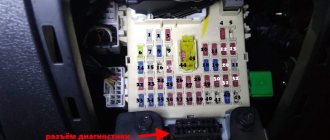
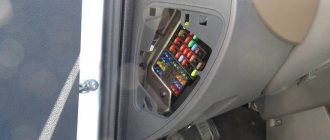
Fuse box in the passenger compartment
Compared to the engine module, the interior inserts are located in a compact panel on the right, lower part of the tidy. The photo above shows the cover of the mounting block on a car from 2006 to 2008.
Fuses for the machine's auxiliary systems, which are not directly related to engine operation, are installed here.
Most of the elements do not affect the behavior and driving characteristics of the vehicle at all.
Security measures
Drivers independently monitor the condition of the protective elements. Make sure that the fuse box in the Kia Spectra interior is kept clean, since dust and moisture sharply reduce the performance of the device.
Maintenance and safety when working with fuses:
- Remove dirt and dust from the surface of the boards with compressed air or a cloth moistened with alcohol or gasoline. Inspect sockets and devices.
- If oxidation is detected, clean the contact points and elements with fine sandpaper. Inspect the power supply unit to see if there are any cracks or damage.
- In electrical wiring, temporary devices are not used and the contact is not closed directly. If a power surge occurs, the node for which the fuse is responsible will burn out.
- Use factory testers and screwdrivers with a plastic handle.
- Do not use devices with a higher rating.
In cars, components and assemblies are connected to each other. The operation of the engine, the comfort and safety of the crew depend on the “little things” - the fuse.
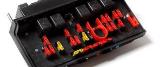
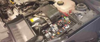
Block under the hood
This part is much more complicated.
The photo above shows how the inserts and relays responsible for the main equipment of the car are mounted. Most of the elements, if they fail, completely block the operation of the machine and disrupt the normal functioning of important systems. Further diagrams with descriptions in Russian are given using the example of a 2007 car in the maximum configuration.
Troubleshooting sequence
Considering that there are many possible reasons for the failure to start the Kia Spectra engine, when troubleshooting a malfunction you should be guided by a single search algorithm. Only in this case a positive result can be achieved in the shortest possible time.
Sequencing:
- Check the residual voltage on the battery. If it is less than 10.5 volts, the battery should be recharged.
- Check all fuses. If there are burnt ones, change them. It is better to first study the fuse layout. In this case, you can control only those elements that are responsible for the power unit systems. This will reduce the verification time. You also need to check the relays to see if any of them are burnt or melted. The main relays responsible for starting: main, fuel pump, starter.
Just in case, you can move all the relays in the connector, the contact may be broken.
- If the starter does not work, try to start it by applying voltage from the positive terminal of the battery to the contact of the solenoid relay (thin wire going to the starter). In this case, the manual transmission must be switched to neutral.
- If the starter rotates the crankshaft, check the condition of the spark plugs. Spark plugs covered with soot, with a damaged electrode, or flooded, should be replaced. As a last resort, they can be cleaned and calcined. It is also necessary to check for spark on all cylinders. This can be done using a control candle.
- Check the performance of the fuel pump. To do this, apply 12 volts to the fuse via the fuel pump power circuit. A characteristic sound should be heard in the rear seat area. You can check the flow of gasoline by disconnecting the fuel line (be sure to place an empty container at its outlet).
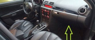
- If previous measures have not brought results, computer diagnostics should be performed. Without it, further search occurs blindly. You can try to temporarily disable the mass air flow sensor, clean the damper, and inject “quick start”.
Kia Spectra fuse diagram
Above is the installer installed under the hood of the car. There are a number of elements present here.
| Number | Purpose |
| 1 | Consumers of the first group. |
| 2 | ABS control system |
| 3 | Interior fuses No. 34, 35. |
| 4 | Second group of consumers |
| 5 | Supply voltage to starter |
| 6 | Power supply for elements 15 and 20 |
| 7 | Radiator Fan Relay |
| 8 | Heating system and air conditioning |
| 9 | Starter control relay |
| 10 | Stove fan |
| 11 | Air conditioning compressor electromagnetic clutch |
| 12 | Headlight corrector for headlights |
| 13 | Emergency crew |
| 14 | Standard central locking |
| 15 | ABS control module |
| 16 | Roof hatch servo drives. |
| 17 | Power windows on the starboard side. |
| 18 | Likewise for the left side of the car. |
| 19 | Rear window washer |
| 20 | Interior lighting |
| 21 | Power supply for headlights |
| 22 | Ignition coils |
| 23/24 | Headlights in low and high beam mode respectively |
| 25 | Oxygen concentration sensor before the catalyst |
| 26 | Likewise, after the catalyst |
| 27 | Fuel pump |
| 28 | Power supply for injector electronics |
| 29 | Air conditioner control |
| 30 | Heated exterior mirrors |
| 31 | Automation of size switches |
| 32 | Rear fog lights |
| 33 | Front PTF |
| 34/35 | Dimensions on the left and right sides, respectively. |
| 36/37 | Low and high beam headlights |
| 38 | Klaxon |
| 39 | Heated rear window |
| 41/45 | Reserve |
You should also clarify the situation with the relay.
| Number | Decoding |
| 50/51 | Right and left headlights respectively |
| 52 | Fuel pump |
| 53/54 | Cabin air conditioning system |
| 55 | Klaxon |
| 56 | Supply voltage to fuses 34 and 35 |
| 60 | Turning on the power windows |
| 61 | Stove fan |
| 62 | Starter |
| 63 | Radiator fan drive |
| 64 | Air conditioning fan |
| 65 | Heated rear window |
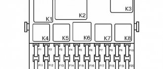
Next, you should consider the small fuse panel inside the car.
| Number | Decoding |
| 1 | Turn signals |
| 2 | Instrument warning lamps |
| 3 | Reserve for automatic transmission |
| 4 | ABS |
| 5 | Driver airbag |
| 6 | Windshield wiper and washer |
| 7 | Head unit |
| 8 | Serves to power the cigarette lighter |
| 9 | Heated seats |
| 10 | Supply voltage to the ECU |
| 11 | Brake lights - lamp line. |
| 12 | Automatic switching off of dimensions. |
Below the main unit there is also a small relay module.
| Number | Purpose |
| 1 | Turns and hazard lights |
| 2 | Central door locking module |
| 3 | Fog lights. |
Spectra turn signal fuse and relay: where is it located?
Installed in the cabin under numbers 1. When replacing parts, there is no need to look for the correct part number. The machine uses standard plug inserts and a five-pin relay; the price on the market fluctuates around 50 rubles.
Cigarette lighter relay and fuse
In the standard wiring, insert No. 8 of the interior module is responsible for powering the outlet. Some drivers prefer to install an additional unit in the rear seats or inside the luggage compartment. It is unreasonable to connect two devices to one line. A separate wire is pulled from the battery and the device is attached to it. Here you will have to ask the owner to show where exactly the protective element is hidden.
Gasoline pump
The fuel pump power supply is controlled through inserts 27 installed under the hood. For 2009 inclusive, the corresponding relay was mounted at position 52.
Heater relay and fuse
On a 2009 car it is installed under the hood at position 10, the required relay is mounted next to it - at number 61.
Window lifters
The right and left sides of the main are powered by fuses 17/18. There is one relay - No. 60.
Low and high beam
Powerful inserts are used to allow both sides of the headlights to be pulled simultaneously. Here it is No. 36/37 for the near and far operating modes of the optics.
Instrument lighting
Connected to fuse 2 installed in the car interior.
Washer
The windshield wiper insert is the same element. The increased power of the element is enough to cover the rating of two highways at the same time.
The insert is mounted at position 6 in the car interior. An auxiliary relay for the motor in the tank and the gear motor is installed near the instruments.
Kia Spectra wiper fuse and relay: where is it located?
The information is listed above.
Where is the starter relay located?
The power unit is installed in the engine compartment at position 62. This allows you to quickly replace a damaged device. Otherwise, the design of the module differs little from common analogues. The retractor is mounted in the housing and replacing it will require complete disassembly of the entire assembly.
Generator regulator relay
Located inside the generator. The layout of the device on other cars of the manufacturer is similar.
Charging relay
The regulator is installed by the manufacturer close to the battery. The device is simple but effective. You can recognize it by its appearance - a small black box installed between the generator and the battery.
Reverse
The lamp is protected by a remote element. To gain access, you will need to remove the plastic lining of the gearshift lever panel. This is where the insert will be mounted.
Heated rear window
The tenna fuse is installed at position 39. The power line switch is mounted in the engine compartment at number 65.
Kia Spectra brake light: where is it located?
They are switched on through insert 11 of the interior panel.
Horn fuse and relay
Compatible with the horn device and located at number 38 in the engine compartment. The corresponding relay No. 55 is also installed nearby. In the standard wiring, when the alarm is turned on, the emergency lights also light up.
Interior lighting
There is only one light in the car. The lamp is low-power and does not require a relay. The design contains fuse No. 20.
Radio tape recorder
For the standard audio system, there is one insert No. 7 installed in the cabin. When installing more efficient acoustics, users often transfer the element to a separately routed line.
central locking
The power element is installed at number 14 in the main block. The button relay is mounted inside the cabin at position 2. It is not clear what the engineers were guided by with such an arrangement.
Speedometer
Protection systems are installed under the dashboard. To gain access to the parts, you will need to remove the shield and reach under it. The necessary equipment will be installed there.
Air conditioner
The manufacturer does not provide clear instructions on where the elements responsible for a specific area of the device are located. The design has 3 fuses - 8, 11 and 29. There are also two relays: 54, 64.
Watch
Power is supplied through an element installed under the tidy. To access the device, remove the dial along with the shield and find the insertion in the power wire.
Reverse speed
The signaling device is connected to the scenes via a special sensor. To gain access to the device, it is necessary to remove the lining of the box. The element will be installed under it.
Ignition
The coil fuse is installed in the engine compartment at position 22.
Dashboard
Controllers and lighting are organized through insert 2 installed under the dashboard.
Kia Spectra: cooling fan relay
The main airflow is protected by fuse 7, and the power lines are turned on by relay 63. Both inserts are installed under the hood of the car.
Fog light fuse
The rear PTFs are powered from No. 32. The front module is connected through fuse element 33. Relay 3 is responsible for turning on the power lines of both units.
Dimensions
The machine is equipped with automatic switches. Inserts 31 and 12 are responsible for turning the lighting on/off. Both elements are separated into separate blocks. The operation of the dimensions on the right and left sides is controlled by inserts 34 and 35.
Kia Spectra: ABS fuse
Insert 2 under the hood is responsible for the operation of the sensors. The control unit is protected by element 15, and the low-voltage sections of the electronics are routed from element 4, mounted in the cabin.
Removal and replacement process
Required tools:
- 7 mm socket head,
- thin material.
- Socket extension,
- Wrench 10 mm,
- slotted screwdriver,
Under the hood
The procedure is performed as follows:
- Apply the parking brake, turn off the ignition, remove the terminal from the negative terminal of the battery.
- Open the cover by pressing the latch on the air filter side.
- Unscrew the nut on the left side of the fender and remove the terminal from the stud.
- Press the latch and remove the part from the holder.
- Remove the safety screw from the blue square leg and remove it.
- Repeat step 5 with the remaining large blocks.
- Disconnect the smaller units by pressing down on their handles with a screwdriver.
- Move the wires to the side and remove the bracket by pressing the latches at the base with a screwdriver.
- Reconnect the terminals and install the removed parts in reverse order.
In the cabin
To disassemble the main and auxiliary units, follow step #1 from the previous section:
- Follow step #1 from the previous method.
- Remove the lower dashboard trim by removing 3 screws: 2 to the right of the steering wheel (at the left corners of the trim) and 1 at the left end of the dashboard.
- Remove the A-pillar cover: Remove the driver's door sill trim by prying it off with a screwdriver wrapped in a cloth.
- Unscrew the piston located on the left driver's footrest.
- Unscrew the 2 nuts securing the fuse box to the body using socket 7.
- Loosen the housing nut using a 7mm socket.
How to remove the fuse box on a Kia Spectra
To quickly dismantle the module you will need to complete the procedure.
- Disconnect battery power. This is necessary to avoid causing a short circuit.
- Remove the mounting block cover.
- Next you will need to disconnect all terminals visible on the surface.
- Next, the plastic panel latches are snapped off and all the screws are unscrewed.
- After this, you need to carefully pull the module towards you and disconnect the wire connectors connected to the back of the panel.
- After this, the part is removed from the machine entirely.
Car alarm connection points for KIA Sorento 2008
| Chain | Color | Location |
| +30 | Red | Black connector |
| +15 | Green/white | White connector B |
| Dimension (+) | Green | Raspberry connector F |
| Turns | White Yellow/black | |
| Ts.Z. Locking | Blue/black | White horizon. Connector K |
| Ts.Z. Locking Strength | Orange | Big vert. Connector A |
| Ts.Z. Unlocking | GREY-black | White horizon. Connector K |
| Ts.Z. Unlocking Force | Blue | Big vert. Connector A |
| The door and trunk limit switches are common with a delay | Brown | Windshield pillar |
| Before. A lion. (-) | Pink/black | White bottom connector To top row |
| Before. Right (-) | Orange/black | White bottom connector K bottom row |
| Rear A lion. (-) | White | White bottom connector To top row |
| Rear Right (-) | GREY-black | White bottom connector To top row |
| Trunk limit (-) | Yellow/black | White bottom connector K bottom row |
| Hood switch (-) | Red Black | Raspberry connector F |
| Gasoline pump | Blue | Big vert. Connector A |
| Chain | Color | Location |
| +12 | green | at the ignition switch |
| ignition | zhel. | at the ignition switch |
| turns | red, orange | at the block before |
| c.z. (-) | green, blue (with black stripes) | at the block before |
| conc. doors (-) | yellow | to the device. panels |
| conc. baggage. (-) | green.orange | to the device. panels |
| petrol | cr. | in the passage threshold |
| cat. ignition | pink.black | corrugated |
| starter | cr. | in the previous block under the hood |
| Chain | Color | Location |
| +30 | Green | Egnition lock |
| +15.1 | Yellow | Egnition lock |
| +15.2 | Orange | Egnition lock |
| ACC1 | White | Egnition lock |
| STARTER1 | Red | Egnition lock |
| Dimension (+) | Red Black | White connector instrument panel |
| Turn 1 | Red | Middle connector instrument panel |
| Turn 2 | Orange | Right connector instrument panel |
| Ts.Z. Locking Strength | Blue red | Black connector under the panel Central locking unit on the left side |
| Ts.Z. unlocking force | White White | Black connector under the panel Central locking unit on the left side |
| Door switch | Yellow | Left connector instrument panel |
| Trunk limit switch | Green/orange | Left connector instrument panel |
| Hood switch | Red Black | |
| Stop | Pedal switch | |
| Tachometer | Green/black | Middle connector instrument panel |
| Generator | Yellow Red | Right connector instrument panel |
| Handbrake | From the handbrake, in the console (untie with a diode) | |
| Glow plugs | Yellow orange | Right connector instrument panel |
| Clutch | Pedal switch |