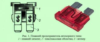
Location
The relay and fuse mounting block is located on the left side of the steering column in the instrument panel.
Types of mounting blocks
Block 2110-3722010
Block 2110-3722010-01
Block 2110-3722010-08
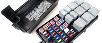
Main block
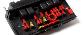
Layout of relays and fuses in the main mounting block.
| № | Purpose |
| K1 | Relay responsible for the operation of car lamps |
| K2 | Electric windshield wiper |
| K3 | A special relay that interrupts the turn lights when the hazard warning lights are activated |
| K4 | Low beam start |
| K5 | High beam launch |
| K6 | Space for installing an additional element |
| K7 | Starting the heated rear window |
| K8 | The VAZ 2110 model does not have this element. |
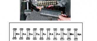
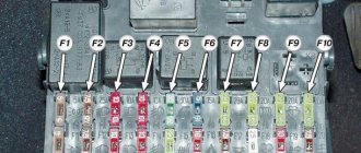
A visual indication of all fuses in the VAZ 2110 car.
Circuit breakers
F1 (5A)
- License plate lights
- Indicator lamp for turning on side lighting
- Trunk light
- Instrument lighting lamps
- Left side marker lamps
F2 (7.5A)
- Left headlight (low beam)
F3 (10A)
- Left headlight (high beam)
F4 (10A)
- Right fog lamp
F5 (30A)
- Door window motors
F6 (15A)
- Socket for portable lamp
F7 (20A)
- Engine Cooling Fan Motor / Horn
F8 (20A)
- Rear window heating element and heating switch contacts)
F9 (20A)
- Recirculation valve
- Window washer motor
- Rear window wiper motor
- Windshield wiper motor
- Headlight cleaner motor
F10 (20A)
- Spare
F11 (5A)
- Starboard side marker lamps
F12 (7.5A)
- Right headlight (low beam)
F13 (10A)
- Right headlight (high beam)
- Indicator lamp for high beam headlights
F14 (10A)
- Left fog lamp
F15 (20A)
- Electric seat heating
- Trunk lock lock
F16 (10A)
- Relay-breaker for direction indicators and hazard warning lights (in hazard warning mode)
- Hazard warning lamp
F17 (7.5A)
- Tail lights (brake lights)
- Body interior light
- Individual backlight lamp
- Ignition switch illumination lamp
- Clock (trip computer)
F18 (25A)
- Glove compartment lamp
- Heater controller
- Cigarette lighter
F19 (10A)
- Door locking
- Rear lights (reversing lights)
- Relay for monitoring the health of brake light and side light lamps
- Direction indicators with warning lamps
- Generator field winding
- On-board control system display unit
- Instrument cluster
- Clock (trip computer)
F20 (7.5A)
- Rear fog lamps
F21
- Spare
F22
- Spare
F23
- Spare
VAZ-2112 wiring diagram
Wiring diagram for a car in a hatchback body (click on the picture to enlarge)
Designations: 1 – Headlight, 2 – Horn, 3 – Main radiator fan, 4 – Starter, 5 – Battery, 6 – Generator, 7 – Gearbox limit switch (reverse), 8 – Actuator in the front passenger door, 9 – Relay power windows permissions, 10 – Starter relay, 11 – Heater fan, 12 – Electric heater partition drive, 13 – Main pump, 14 – Washer reservoir sensor, 15 – Driver’s door actuator, 16 – Front passenger window selector, 17 – Fifth wheel release button doors, 18 – Heater fan resistance unit, 19 – Main wiper motor, 20 – Driver's window lift selector, 21 – Front passenger's window lift motor, 22 – Central locking, 23 – Exterior light switch, 24 – Brake fluid leakage sensor, 25 – Additional pump , 26 – Driver's window lift motor, 27 – PTF on indicator, 28 – PTF switch, 29 – Dashboard , 30 – Heated glass on indicator, 31 – Heated glass switch, 32 – Steering column selector switch, 33 – PTF relay, 34 – Ignition switch , 35 – Main fuse block, 36 – Illumination of heater controls, 37 – Hazard warning button, 38 – Heater control controller, 39 – Glove compartment lighting, 40 – Glove compartment lid end cap, 41 – Cigarette lighter, 42 – BSK – display unit, 43 – Ashtray illumination, 44 – 12V socket, 45 – Instrument lighting switch, 46 – Actuator in the right rear door, 47 – Right rear passenger window selector, 48 – Clock, 49 – Right rear passenger window motor, 50 – Brake limit switch (closed – pedal is pressed), 51 – Left rear passenger window motor, 52 – Left rear passenger window selector, 53 – Actuator in the left rear door, 54 – Turn signal, 55 – Handbrake limit switch (closed – handbrake on), 56 – Rear wiper motor, 57 – Navigator’s lamp, 58 – Interior lamp, 59 – Temperature sensor in the heater, 60 – Limit switch for an open front door, 61 – Limit switch for an open rear door, 62 – Trunk lighting, 63 – Rear optics (on the body), 64 – Rear optics ( on the fifth door), 65 – License plate illumination.
Relay
K1
- Lamp integrity monitoring relay (4412.3747 / 2110-3747410)
K2
- Windshield wiper relay breaker (524.3747 / 2110-3747710)
K3
- Relay-breaker for direction indicators and hazard warning lights (492.3747 / 2108-3747010-02)
K4
- Relay for low beam headlights (113.3747 / 2105-3747210-10)
K5
- Headlight high beam relay (113.3747 / 2105-3747210-10)
K6
- Additional relay (71.3747-01 / 2110-3747310-01)
K7
- Relay for turning on the heated rear window (113.3747 / 2105-3747210-10)
K8
- Rear fog lamp relay (113.3747 / 2105-3747210-10)
What are the VAZ 2110 fuse box relays responsible for?
K1 – relay for monitoring the health of light bulbs; K2 – front wiper relay; K3 – repeater and alarm relay; K4 – low beam relay; K5 – high beam relay; K6 – additional relay; K7 – relay for turning on the heated rear window; K8 – backup relay (not installed on 110 series vehicles);
F1-F20 in the diagram are fuses. The circuits in the car are protected by fuses based on a certain rated current (in A). The battery charging circuit, generator circuit, ignition and engine starting are exceptions.
To replace a faulty fuse, first find the one that has blown, then eliminate the reason why it was damaged and then install a new one. Below is a list of fuses and information on each one.
* Never replace fuses with jumpers, this can lead to failure of various components and elements, including failure of the wiring tracks in the fuse box and even a car fire.
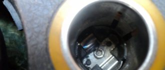
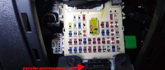
Additional fuses and relays
Location
Additional fuses and relays are installed behind the side trim of the console, secured with two screws, on the right side of the instrument panel.
Circuit breakers
1 (15A)
- Ignition module
- Controller
2 (15A)
- Canister purge valve
- Vehicle speed sensor
- Oxygen sensor (heating)
- Air flow sensor
3 (15A)
- Fuel pump relay
- Fuel pump
- Injectors.
Electrical diagram of the VAZ-21104 ECM with controller 21124-1411020-30/31/32
1 – block of the ignition coil wiring harness to the ignition system harness; 2 – block of the ignition system harness to the ignition coil wiring harness; 3 – ignition coils; 4 – immobilizer warning sensor; 5 – immobilizer control unit; 6 – spark plugs; 7 – nozzles; 8 – diagnostic block; 9 – block of the ignition system harness to the ABS cabin group harness; 10 – controller; 11 – electric fuel pump; 12 – block of the ignition system harness to the fuel level sensor harness; 13 – fuel level sensor harness connector to the ignition system harness; 14 – block of the ignition system harness to the injector harness; 15 – injector harness block to the ignition system harness; 16 – block of the ignition system harness to the side door harness; 17 – speed sensor; 18 – idle speed regulator; 19 – throttle position sensor; 20 – coolant temperature sensor; 21 – mass air flow sensor; 22 – oil pressure warning lamp sensor; 23 – phase sensor; 24 – oxygen sensor; 25 – crankshaft position sensor; 26 – knock sensor; 27 – solenoid valve for purge of the adsorber; 28 – oil level sensor; 29 – coolant temperature indicator sensor; 30 – block of the ignition system harness to the instrument panel harness; 31 – instrument panel harness connector to the ignition system harness; 32 – ignition relay; 33 – ignition relay fuse; 34 – fuse for the electric fuel pump power supply circuit; 35 – electric fuel pump relay; 36 – electric fan relay; 37 – controller power supply fuse; 38 – ignition system harness block to the air conditioner connector; 39 – instrument cluster; 40 – ignition switch; 41 – electric fan of the cooling system; 42 – on-board control system unit; 43 – starter relay; 44 – contacts of the 8-terminal blocks of the instrument panel harness and the front harness; 45 – contacts of the 21-terminal blocks of the instrument panel harness and the rear harness; 46 – trip computer; 47 – diagnostic connector.
Reasons for premature failure of fuses
- A natural factor is the duration of operation without intermediate prevention;
- Ingress of moisture, formation of condensation, oxidation of terminals, drying out of the insulating layer, open circuit of the electrical supply;
- Mechanical damage, accident, impact, collision;
- Damage to the car fender, windshield, which contributed to damage to the mounting block;
- Short circuit in the electrical supply circuit;
- Exposure to ultraviolet rays.
If after replacing the modules the equipment does not work, then the power supply circuit line is most likely damaged. In the worst case scenario, part failure. Carefully inspect the wiring sections from the battery, generator, starter to the relay switch.
The operating instructions for the technical means indicate the interval before replacing the modules of the mounting block is 40,000 km. In practice, the resource is 5 – 7 thousand km longer.
To prevent premature wear of modules, systematically check the condition of the wiring insulation, the quality of fixation of the terminals, and remove oxidation with fine sandpaper.
As consumables, purchase original domestically produced parts. Check the catalog numbers with the data specified in the instruction manual. Imported analogues are comparable in quality to the Russian manufacturer, but the price is twice as expensive
Stories from our readers
“Fucking basin. "
Hi all! My name is Mikhail, now I’ll tell you a story about how I managed to exchange my two-wheeler for a 2010 Camry. It all started with the fact that I began to be wildly irritated by the breakdowns of the two-wheeler, it seemed like nothing serious was broken, but damn it, there were so many little things that really started to irritate me. This is where the idea arose that it was time to change the car to a foreign car. The choice fell on the melting Camry of the tenth years.
Yes, I had matured morally, but financially I just couldn’t handle it. I’ll say right away that I am against loans and taking a car, especially not a new one, on credit is unreasonable. My salary is 24k a month, so collecting 600-700 thousand is almost impossible for me. I started looking for different ways to make money on the Internet. You can’t imagine how many scams there are, what I haven’t tried: sports betting, network marketing, and even the volcano casino, where I successfully lost about 10 thousand ((The only direction in which it seemed to me that I could make money was currency trading on the stock exchange, they call it Forex. But when I started delving into it, I realized that it was very difficult for me. I continued to dig further and came across binary options. The essence is the same as in Forex, but it’s much easier to understand. I started reading forums, studying trading strategies. I tried it on a demo account, then opened a real account. To be honest, I didn’t manage to start earning money right away, until I understood all the mechanics of options, I lost about 3,000 rubles, but as it turned out, it was a precious experience. Now I earn 5-7 thousand rubles a day. I managed to get the car buy after half a year, but in my opinion this is a good result, and it’s not about the car, my life has changed, I naturally quit my job, I have more free time for myself and my family. You’ll laugh, but I work directly on the phone)) If If you want to change your life like me, then here’s what I advise you to do right now: 1. Register on the site 2. Practice on a Demo account (it’s free). 3. As soon as you get something on the Demo account, top up your REAL ACCOUNT and go to REAL MONEY! I also advise you to download the application to your phone, it’s much more convenient to work from your phone. Download here.
- K1 – lamp health monitoring relay (contact jumpers are shown inside, which are installed instead of the relay);
- K2 – windshield wiper relay;
- K3 – relay-interrupter for direction indicators and hazard warning lights;
- K4 – headlight low beam relay;
- K5 – headlight high beam relay;
- K6 – additional relay;
- K7 – relay for turning on the heated rear window;
- K8 – backup relay (not installed on vehicles of the VAZ-2110 family);
Main settings
The fuse box is located under the decorative panel to the left of the steering column. Removing it is quite simple: press the latch and lower the structure down. Once you have access to the fuses, they can be removed and checked for integrity using a millimeter. The block contains only 20 fuses, designed for different current strengths. Just look at the color of the fuse to determine what amperage it is designed for:
- tan runs at 5 amps;
- darker brown – at 7.5;
- red – at current strength 10;
- saturated blue – at 15;
- bright yellow is for 20;
- colorless or transparent – by 25;
- green – by 30.
Source