Volkswagen Golf 2
generation was produced with sedan and hatchback bodies not only in Germany, but also in the UK, Finland, Japan, the USA and some other countries of the current European Union. Years of production: 1983, 1984, 1985, 1986, 1987, 1988, 1989, 1990, 1991 and 1992. The model underwent the most significant restyling in 1987. More than 6.3 million cars were produced on all continents. In this article you will find a description of the fuse and relay blocks of the 2nd generation Volkswagen Golf, with photo examples of blocks, their diagrams and designations of elements. Note the fuse responsible for the cigarette lighter. In conclusion, we will offer for download a book with a complete description of electrical circuits.
The number of elements in the main unit may differ from those shown and depends on the configuration, year of manufacture and country of delivery. The current purpose specifically for your car will be printed on top of the protective cover - the box. And if the generation is not suitable, study the description for the 3rd. We also note that the current schemes are suitable for the Jetta 2 model.
Change in fuse diagram after 1988
After 1988, fuses and relays were located as in the figure.
Decoding of PP values on a 2nd generation VolksWagen Golf.
| Electrical circuit or device | Denomination, A | Color | № |
| Electric motor of the engine cooling system fan | 30 | Green | 1 |
| Brake light bulb, tail light | 10 | Red | 2 |
| Car radio, cigarette lighter, clock in the instrument panel, interior lighting | 10 | Red | 3 |
| Emergency button | 15 | Blue | 4 |
| +12V fuel pump power supply | 15 | Blue | 5 |
| Front fog lights | 15 | Blue | 6 |
| Side light bulb, right side tail light | 10 | Red | 7 |
| Side light bulb, left side tail light | 10 | Red | 8 |
| Headlight high beam bulb, left side | 10 | Red | 9 |
| Headlight high beam bulb, right side | 10 | Red | 10 |
| Windshield wipers, headlight washer motor, windshield washer motor | 15 | Blue | 11 |
| Rear view window wiper, rear view window washer motor, electric exterior rear view mirror, engine coolant level indicator | 15 | Blue | 12 |
| Heated rearview glass, heated rearview mirror | 20 | Yellow | 13 |
| Interior heating fan drive | 20 | Yellow | 14 |
| Automatic transmission selector light, reverse gear light | 10 | Red | 15 |
| High pitch horn | 15 | Blue | 16 |
| Fuel supply interrupter for the internal combustion engine, heating of the intake manifold, PU of the carburetor internal combustion engine | 10 | Red | 17 |
| Low-pitched horn, heated front car seats, handbrake indicator | 10 | Red | 18 |
| Turn signal bulbs, front and rear | 10 | Red | 19 |
| Front fog lights, rear license plate light, glove compartment light | 10 | Red | 20 |
| Right low beam bulb in the headlight | 10 | Red | 21 |
| Left low beam bulb in headlight | 10 | Red | 22 |
| Relay connector description | Note | Designation on the diagram | |
| Reserve connector | I | ||
| Air heating in the intake manifold | Carburetor internal combustion engine | II | |
| Fuel pump | Single injection | ||
| Pre-heating plugs | Diesel internal combustion engine | ||
| Front seat belt buzzer | Diesel internal combustion engine | III | |
| Gear selector | Automatic transmission | IV | |
| Air conditioning compressor | V | ||
| Two-tone horn | VI | ||
| Front fog lights | VII | ||
| Power relief of terminal X | VIII | ||
| Reserve connector | IX | ||
| Headlight washer | X | ||
| Rear window wiper and washer motor | XI | ||
| Emergency crew | XII | ||
| Seat belt buzzer | XIII | ||
| Heated rear view glass, engine oil pressure indicator, seat belts | XIV | ||
| Windshield washer motor | XV | ||
| Adjusting idle speed | Single injection | XVI | |
| Reserve connector | Air conditioner | XVII | |
| Electric drive of the internal combustion engine cooling radiator fan | Carburetor internal combustion engine | XVIII | |
| Coolant level indicator in internal combustion engine | Diesel internal combustion engine | XVIII | |
| Reserve connector | Window lifters | XIX | |
| Heated driver's seat | XX | ||
| Heated front passenger car seat | XXI | ||
| Fuel supply switch | Carburetor | XXII | |
| Reserve connector | XXIII | ||
| Reserve connector | XXIV |
Removal and replacement
The replacement process is identical for all versions of the FV. To replace, you will need a screwdriver or wrenches, depending on whether the power supply is attached to the body with bolts or self-tapping screws. Decide which tool you need, and you can start removing.
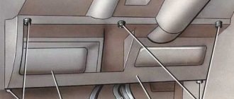
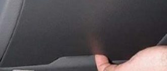
- Using a screwdriver, disconnect the dashboard trim behind which the power supply is installed in your car.
- Unscrew the screws securing the power supply to the car body.
- Pull out the device: it will hang on the wires.
- Take the new power supply unit and, one by one, disconnecting it from the old device, insert all the necessary wires into the connectors of the new power supply unit.
- Install the new power supply in place by tightening the fastening screws and closing the instrument panel trim.
Change in fuse diagram after 1988
Decoding of PP values on a 2nd generation VolksWagen Golf car after 1988.
| Protected electrical circuit, system or device | Fuse rating, A | Color coding | Number on the diagram |
| Right low beam bulb in the headlight | 10 | Red | 1 |
| Left low beam bulb in headlight | 10 | Red | 2 |
| Rear license plate light, instrument panel light bulbs | 10 | Red | 3 |
| Glove compartment light | 15 | Blue | 4 |
| Windshield wipers, windshield washer motor | 15 | Blue | 5 |
| Electric motor of the engine cooling system fan | 20 | Yellow | 6 |
| Side light bulb, left side tail light | 10 | Red | 7 |
| Heated rear view glass | 20 | Yellow | 8 |
| Front fog lights | 15 | Blue | 9 |
| Headlight high beam bulb, right side | 10 | Red | 10 |
| Headlight high beam bulb, left side | 10 | Red | 11 |
| High pitch horn | 10 | Red | 12 |
| Heated washer jets, rear license plate light | 10 | Red | 13 |
| Diesel fuel supply interrupter | 10 | Red | 14 |
| Dashboard | 15 | Blue | 15 |
| Emergency button | 10 | Red | 16 |
| Not used | 17 | ||
| Engine cooling radiator fan drive, air conditioning compressor | 30 | Green | 18 |
| Brake light bulb, tail light | 10 | Red | 19 |
| Interior light bulb | 15 | Blue | 20 |
| Car radio, cigarette lighter | 10 | Red | 21 |
| Relay connector description | Note | Designation on the diagram | |
| Air conditioning compressor | I | ||
| Rear window wiper and washer motor | II | ||
| Ignition system controller | III | ||
| Power relief of terminal X | IV | ||
| Coolant level indicator in internal combustion engine | V | ||
| Emergency crew | VI | ||
| Headlight washer | VII | ||
| Adjusting windshield wiper modes | VIII | ||
| Seat belt buzzer | IX | ||
| Seat belt buzzer | X | ||
| Two-tone horn | Jumper | XI | |
| Pre-heating plugs | Diesel internal combustion engine | XII | |
| Electric drive of the internal combustion engine cooling radiator fan | XIII | ||
| Air heating in the intake manifold | XIV | ||
| Hydroelectric ABS unit | XV | ||
| ABS system controller | XVI | ||
| Reserve connector | XVII | ||
| Reserve connector | Seat adjustment | XVIII | |
| Automatic transmission | XIX | ||
| Plug Controller | Diesel internal combustion engine | XX | |
| Power window motor | XXI | ||
| Reserve connector | ABS system | XXII | |
| Reserve connector | Air conditioning compressor | XXIII | |
| Reserve connector | Electric window drive | XXIV |
Features of replacing fuses in Golf 2
Procedure
To replace an element in the fuse box in a Golf 2, you must follow the following procedure:
- Remove the cover from the block.
- Identify the faulty element by the melted walls and remove it using plastic tweezers.
- Insert a new part in accordance with the pinout of the fuse box in Golf 2. The fuse must be designed for the same amperage, which can be determined by the color and special inscription on the holder.
- Close the block with a lid.
If the new fuse quickly blows again, the corresponding electrical circuit must be carefully checked for overloads.
You cannot replace a damaged element with wire or other improvised materials. This may result in equipment failure or even a fire in the unit. For safety reasons, it is best to keep a small set of spare fuses in your car at all times. For this purpose, special fastenings are provided in the block.
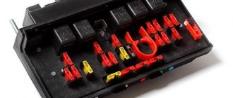
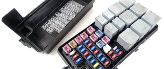
Appearance of fuses in Volkswagen Golf 2
Recommendations
Recommendations for replacement:
- Before starting work, it is advisable to turn off the electrical circuit in which the fuse has failed.
- It is not recommended to use grips that are too hard as they can scratch the contacts.
- If a constantly blowing fuse controls the operation of several circuits, you need to alternately connect one circuit to it and check it for errors. Only in this case will it be possible to find the true cause of the malfunction.
- Using a fuse with a higher amperage may cause damage or fire.
General purpose relay
Relay (000 953 227 A) - Relay for comfort turn signalsRelay 53 (141 951 253 B) - Horn relay, Fog light relay, Relay for fuel pump (diesel, 4Motion), Relay 79 (191 927 841) - Luggage lid relay compartmentRelay 87 (191 957 917 A) - Freewheel lock control unitRelay 100 (7M0 951 253 A)
— Relay with normally open contactRelay 103 (357 911 253) — Glow plug relay (diesel)Relay 109 (1J0 906 381 A) — Fuel pump relayRelay 147 (1H0 959 142) — Radio/telephone relayRelay 167 (191 906 383 C) — Relay with normally open contact for fuel pumpRelay 175 (3A0 927 181)
— Starter activation relay for AKPRRelay 181 (1J0 959 485) — Radiator fan shutdown delay relayRelay 185 (3B0 911 251) — Relay with normally open contact (Starter interlock switch) Relay 192 (1J0 955 531 A) — Windshield washer intermittent mode control unit/ windshield wiper for vehicles with rain sensorRelay 206, 444 (1J0 927 841)
— Relay with normally open contact for vehicles with electronic support system. well. stable ESPRelay 393 (4B0 919 471 A) - Burnt-out lamp monitoring relayRelay 377 (4B0 955 531 A) - Intermittent wiper control unitRelay 389 (4B0 955 531 C) - Intermittent wiper control unitRelay 404 (7M0 951 253 C)
— Universal relay (APF) Relay 407 (1J0 947 221 A) — Luggage compartment lid control unit for vehicles without central locking Relay 409 (191 906 383 C) — Fuel pump relay Relay 450, 452 (1J0 907 487 B) — Multifunction steering control unit wheelsRelay 456 (3U0 941 597 A)
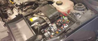
Fuses under the hood
On vehicles with diesel engines, the electrical power supply circuit for the glow plugs is protected by a high-power fuse in the form of a fuse link.
p, blockquote 13,0,0,0,0 —>
p, blockquote 14,0,0,0,0 —>
On some models, when the radiator cooling fan is turned on, a fuse link can also be used.
p, blockquote 15,0,0,0,0 —>
Leaky cylinder head gasket
This malfunction does not occur often, but, in addition to deteriorating the performance of the standard heating element, it threatens significant problems for the power unit. Diagnosing the problem is easy. If an antifreeze leak is accompanied by a change in exhaust color from clear to solid white, this indicates that fluid is entering the cylinders and then into the muffler. A leaking BC head gasket seal is a serious problem because coolant will also enter the lubrication system, reducing the viscosity of the engine oil, which can significantly reduce engine life. Therefore, if a malfunction is detected, the gasket should be replaced as soon as possible. This procedure is quite responsible, but it can be done independently. If you have no experience in disassembling the cylinder head, it is better to turn to specialists to avoid mistakes typical for beginners.
Faulty thermostat
A stuck thermostat valve is a sign of a malfunction in all cars without exception. Typically, while driving, the engine should warm up to operating temperature in no more than 10 minutes (in winter, idling may take much longer). If the movement of the valve is impaired, which is facilitated by the formation of scale on the internal walls of the thermostat, it begins to wedge and eventually stops moving altogether, and this can happen in an open, closed or intermediate position. Replacing the thermostat is a simple procedure, the main problem is to disassemble the pipes, since usually the clamp and the pipe itself stick to the fitting and you will have to tinker with their removal. Steps to replace the thermostat:
- unscrew the RB cap;
- place a container for antifreeze under the thermostat;
- remove the pipes;
- Using a 10mm wrench, unscrew the two bolts that secure the thermostat to the engine;
- removes the thermostat along with the gasket;
- wait 10-15 minutes for the coolant to drain;
- install a new part;
- refill with new antifreeze.
Additional fusible elements
In some versions of Volkswagen Golf 3rd generation vehicles, additional fuses may be used. The following additional elements are used in the interior fuse and relay module:
- rated 30A - power supply to the ABS system relay;
- rated 30A - power supply to the relay of the hydroelectric unit of the ABS system;
- rated 10A - air conditioning compressor for cars without climate control;
- rated 30A - interior ventilation motor with the ClimaTronic system;
- with a nominal value of 5A - controller of the ClimaTronic system;
- rated 5A - +12A power supply to the on-board network of a towed trailer.
For a diesel internal combustion engine, an additional PP for the engine warm-up system is used, with a rated current of 60 A. It is located separately, on the engine panel under the hood.
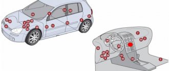
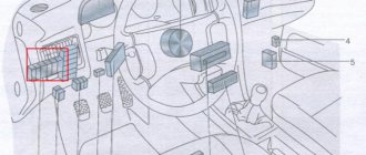
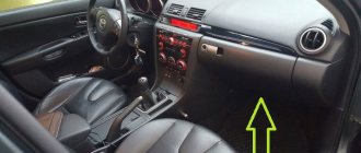
Fuse and relay box
It is located in the car interior under the instrument panel, on the driver's side under a protective cover.
Photo - example
Option 1
Option 1 (models before 08.1987)
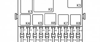
Scheme
Description of fuses
| 1 | 30A Electric fan |
| 2 | 10A Brake light |
| 3 | 10A Cigarette lighter, radio, clock, interior light |
| 4 | 15A Hazard alarm |
| 5 | 15A Fuel pump |
| 6 | 15A Fog lamp |
| 7 | 10A Rear left parking light |
| 8 | 10A Rear right side light |
| 9 | 10A High beam right headlight, high beam indicator lamp |
| 10 | 10A High beam left headlight |
| 11 | 15A Windshield wiper, windshield washer, headlight washer |
| 12 | 15A Windshield wiper and washer for the rear door glass, coolant level warning lamp, electric outside rear view mirror |
| 13 | 20A Heated rear window of the tailgate, heated outside rear view mirror |
| 14 | 20A Heater fan |
| 15 | 10A Reversing lamp, gear selection lamp (automatic transmission) |
| 16 | 15A High tone horn |
| 17 | 10A Automatic carburetor starter, electric intake pipe heater, forced idle fuel shut-off valve |
| 18 | 10A High and low tone horn, front seat heating, parking brake light |
| 19 | 10A Turn signal |
| 20 | 10A License plate light, glove box light, fog lights |
| 21 | 10A Low beam left headlight |
| 22 | 10A Low beam right headlight |
In this version, fuse number 3 at 10A is responsible for the cigarette lighter.
Relay designation
| I | Free |
| II | Intake pipe heater relay |
| Fuel pump relay | |
| Glow plug relay | |
| III | Seat belt warning relay |
| IV | Gear Selection Relay |
| V | Air conditioner relay |
| VI | Horn relay |
| VII | Fog light relay |
| VIII | Contact relief relay x |
| IX | Free |
| X | Washer relay |
| XI | Tailgate wiper and washer relay |
| XII | Alarm relay |
| XIII | Seat belt warning relay |
| XIV | Seat belt warning relay, heated rear window, pressure warning lamp |
| XV | Headlight washer relay |
| XVI | Idle speed increase relay |
| XVII | Fuse for rear fog lamp, air conditioner |
| XVIII | Fan relay |
| Coolant level alarm relay | |
| XIX | Power window fuse |
| XX | Driver seat heating relay |
| XXI | Passenger seat heating relay |
| XXII | Fuel cut-off relay for forced idle |
| XXIII | Free |
| XXIV | Free |
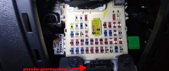
Option 2 (models from 08.1987)
Scheme
Purpose of fuses
| 1 | 10A Low beam left headlight |
| 2 | 10A Low beam right headlight |
| 3 | 10A Instrument lamp, license plate lamp |
| 4 | 15A Glove compartment lamp |
| 5 | 15A Windshield wiper and washer |
| 6 | 20A Heater fan |
| 7 | 10A Right rear light, parking light |
| 8 | 20A Heated rear window |
| 9 | 15A Fog lights |
| 10 | 10A High beam left headlight |
| 11 | 10A High beam right headlight |
| 12 | 10A Horn |
| 13 | 10A Reversing light, heated washer |
| 14 | 10A Fuel cut-off valve (diesel engine) |
| 15 | 15A Instrument panel |
| 16 | 10A Hazard Alarm |
| 17 | Free |
| 18 | 30A Electric fan, air conditioning relay |
| 19 | 10A Brake light |
| 20 | 15A Interior lighting |
| 21 | 10A Radio and cigarette lighter |
In this version, fuse number 21 is responsible for the cigarette lighter
Relay decoding
| I | Air conditioner relay |
| II | Tailgate wiper relay |
| III | Ignition system relay |
| IV | Contact relief relay x |
| V | Coolant level alarm relay |
| VI | Alarm relay |
| VII | Headlight washer relay |
| VIII | Windshield wiper switching relay |
| IX | Seat belt warning relay |
| X | Fog light relay |
| XI | High and Low Pitch Horn Relay |
| XII | Glow plug relay |
| XIII | Electric fan relay |
| XIV | Intake pipe heating relay |
| XV | ABS pump relay |
| XVI | ABS relay |
| XVII | Free |
| XVIII | Free |
| XIX | Automatic transmission relay |
| XX | Glow plug control relay |
| XXI | Power window relay |
| XXII | ABS fuse |
| XXIII | Air conditioner fuse |
| XXIV | Power window fuse |
General purpose relay
- 4 or 29 - seat belt warning relay
- 13 - air conditioning compressor
- 15 — PTF
- 18 — unloading of tire X
- 19 or 99 - windshield wipers (99 - with adjustable pause)
- 21 - hazard warning indicators
- 22 — trailer direction indicators
- 30, 32 — Injection and ignition system relay
- 31 - secondary air valve relay
- 32 - ECU power supply
- 33 — headlight washer
- 36 — buzzer (signalling lights off)
- 42 - engine overheat relay (also 43)
- 43 - indicator of drop in coolant level (up to 91)
- 46 — preheating time relay
- 53 - two-tone signal. (solid color - jumper)
- 54 — cessation of power supply to the pump. XX
- 55 - increase in forced fuel supply. XX
- 61 — heating vp. collector
- 67 or 80 - fuel pump
- 72 - rear wiper
- 83 - freewheel lock relay (only on Syncro model)
- 90 - fuel purge pump relay
- 167 — Fuel pump or pre-heater relay (diesel) The following can be installed in any order:
- 220 - after-run relay
- 13 — electromagnetic clutch of the air inlet damper drive
- 79 - ABS ECU
- 78 - ABS pump
- 59 — heated seats
Checking the health of fuses
If the functionality of any vehicle device malfunctions, it is necessary, using Tables 1 and 2, to determine which fuses serve this element. Then you need to turn off the ignition.
In some cases (failure of the engine control unit, generator, side lights, cigarette lighter, etc.), it is better to remove the negative terminal of the battery. Then, using special dielectric pliers (you can use pliers), you need to disassemble the necessary fuses.
Testing fuses without removing them from the block may give an erroneous result.
Fuses in transparent housings can be checked visually. It should be remembered that this method of fault monitoring does not have a 100% guarantee, since sometimes it is not possible to see a microcrack in the conductive insert.
It is best to use the multimeter in the "diode", "resistance" or "continuity" test positions. The resistance value of a good fuse is approximately zero. The resistance of a blown fuse tends to infinity (the multimeter displays “1”).