03/04/2022 13,683 VAZ 2109
Author: Ivan Baranov
Modern cars are mostly equipped with an internal combustion engine. In order to cope with various unforeseen situations on the road, you need to know the structure of the machine. The article describes the operating procedure of the VAZ 2109 cylinders, as well as possible malfunctions in the operation of the power unit.
[Hide]
The operating order of the VAZ 2109 cylinders
Quite often, car owners ask the question why they need to know the operating order of the VAZ 2109 cylinders if the car is working normally.
The fact is that knowledge of the operating principle of the internal combustion engine (ICE) is necessary in order to detect the problem in time and take measures to eliminate the malfunction. Timely measures taken will protect the engine from serious damage. The VAZ 2109 uses a 4-cylinder engine. There are four strokes in engine operation:
1. “Intake”, in this stroke, fuel is supplied to the system, which is mixed with air. At this stage, the cylinder is filled with the working mixture. 2. "Compression". At this stage, the working mixture is compressed due to the movement of the piston in the cylinder. 3. "Expansion". The compressed air-fuel mixture is ignited by a spark generated by the spark plug. As a result of combustion of the mixture, the resulting gases expand and, under high pressure, push the piston down, this movement is transmitted to the crankshaft. 4. "Release". At this stage, through the open exhaust valves, exhaust gases enter the vehicle's exhaust system.
To ensure smooth engine operation, various operating patterns are used to determine the sequence of cylinder operation. The most common scheme is 1-3-4-2; it is this combination that is used in the VAZ 2109. The numbers correspond to the accepted numbering of the cylinders, in which the front part of the engine is usually used as the reference point.
Thus, the working cycle of the VAZ 2109 internal combustion engine is represented by the following sequential actions:
1. In the 1st cylinder there is a downward movement, a working stroke, that is, combustion of the working mixture and expansion of gases. 2. “Compression” occurs in the 3rd cylinder, the piston moves up. 3. In the 4th cylinder there is an “intake”, the piston moves down, and the working mixture is pumped into the cavity. 4. “Exhaust” is carried out in the 2nd cylinder; exhaust gases leave the cavity through the exhaust valves.
Now let's look at several cases of malfunctions in the operation of the VAZ 2109 engine. In order to find out the cause of the breakdown, you should use the following algorithm of actions:
• Start the engine and go to idle speed. Listen to the sounds of exhaust. If uniform, periodic popping noises are observed, then most likely the cylinder is not working due to suction, a faulty spark plug, reduced compression or lack of spark. • Inspect the spark plugs; there should be no traces of soot, oxidation or moisture. The gap between the electrodes should average 0.8-0.9 mm. • Replace the spark plug set. • Check the condition of the high-voltage wires of the ignition system. The insulation must be intact, and the contacts must not be oxidized or burnt. If the wires are damaged, they must be replaced. • Inspect the rotor and distributor cap. The lid must be intact, without cracks and clean, without traces of soot. The carbon contact must not be worn or damaged. The rotor must also be intact and have no signs of burnout. All faulty elements must be replaced. • If, after the actions taken, interruptions in the operation of the cylinders continue, then you should contact a service station for a full diagnosis and adjustment of the ignition system, which should be carried out on a stand. • It should be noted that normally the compression should be above 1.1 MPa. If fluctuations within 0.1 MPa are observed in one of the cylinders, then it is necessary to urgently repair the engine itself.
Thus, it is quite obvious that knowledge of engine operation will allow timely repair work and avoid serious breakdowns.
Causes of failure
Once you have figured out the order of operation of the elements, you can begin diagnosing the motor. As stated above, the failure of one or more components is directly related to the motor tripping, so it is necessary to find out the reasons for its failure.
- Start your VAZ 2106, let it run in neutral gear. Then go to the muffler and listen to how the exhaust pipe works. If there are no interruptions in the functioning of the engine, the exhaust sound will be smooth and soft. If you hear popping noises from time to time, this means that one of the components is not functioning due to a broken spark plug. This may also indicate a lack of spark at the spark plug, excessive oxygen leakage, or an incorrect compression level.
- If the exhaust pipe pops are irregular, that is, they occur from time to time, then this may indicate incorrect operation of the carburetor, failure of the spark plugs, or their wear. This may also indicate a faulty ignition. To fix the problem, you should diagnose the carburetor, ignition system, and replace broken spark plugs.
Non-working car spark plugs
Distributor cover VAZ 2106
Auto working spark plugs
If, as a result of these actions, the problem of engine tripping remains, then contact a specialist and diagnose the ignition system.
This is done using specialized equipment, so it is unlikely that you will be able to accurately make a “diagnosis” yourself.
This is a reminder for drivers of the VAZ 2107 (also relevant for other classics), I decided to create it because minor technical questions often arise, and it takes a lot of time to find the answer. And here everything is in one place. Save this reminder in your bookmarks or on your page on a social network, and use the social network buttons under the article for your health.
So, VAZ 2107 technical characteristics, dimensions, parameters.
VAZ 2107 was produced from March 1982 to April 2012. It has been produced in Egypt since 2006 to this day. It has a 5-seater sedan-type body, in-line 4-cylinder gasoline engines, paired with a 4 or 5-speed manual transmission. It is included in the class of subcompact cars, according to the European classification - class “B”. And not C, as they say on the forums. C class is Ford Focus, KIA Ceed, etc. Wheel formula 4x2, rear wheel drive. The ancestor is the Italian Fiat 124.
General parameters of the VAZ 2107
Length - 4145 mm Width - 1620 mm Height - 1446 mm Base - 2424 mm Front wheel track - 1365 mm Rear wheel track - 1321 mm Ground clearance - to the front suspension cross member - 159 mm, to the rear axle beam - 154, up to muffler housing - 120 mm. Not bad, for example in the Opel Zafira, only 150 mm to the highest point. Load capacity - 400 kg Trunk volume - 385 liters Curb weight - 1060 kg Gross weight - 1460 kg Towed trailer weight, without brakes - 300 kg, with brakes - 600 kg.
VAZ 2107 engines
The VAZ 2107 was equipped with several engines (for Russia and the USSR), these are:
VAZ 2103 engine (8 cells, 1500 cm3, 71 hp, carburetor) VAZ 2105 engine (8 cells, 1300 cm3, 64 hp, carburetor, timing belt drive) VAZ 2106 engine ( 8 class, 1600 cm3, 79 hp, carburetor) VAZ 2104 engine (8 class, 1500 cm5, 68 hp, central injection) VAZ 21067 engine (8 class, 1600 cm3, 74 hp, distributed injection) RPD engine (rotary, 1300 cm3, 140 hp) Piston
diameter and stroke:
- for 1300 = 79 mm x 66 mm - for 1500 = 76 mm x 80 mm - for 1600 = 79 mm x 80 mm - for 1700 = 82 mm x 80 mm Compression ratio for all engines - 8.5 Cylinder operating order: 1-3-4-2 For carburetor VAZ 2107, DAAZ 2107-1107010 carburetors and their modifications were used.
A-92 gasoline is used as fuel. The injector for Euro-3 standards is already designed for A-95 gasoline. Spark plugs for VAZ 2107:
- for carburetor engines - A17DVR or A17DV-10;
- for injector - A17DVRM. Oil for VAZ 2107:
For all classic engines, the optimal choice is semi-synthetic 5W40. If your region has severe frosts, and most of the time it is below minus 30, then choose 0W40. If your frosts are not severe and the summer is hot, then the oil is better than 10W40. Oil change is done once every 10,000 km
All-metal, load-bearing, with 4 doors. Body rigidity - 7200 Nm/deg. The width of the interior of the VAZ 2107, and all the classics in general (from the rear door trims at the seat level) - 1250 mm Between the central pillars of the cabin, at a level of 80 cm from the floor - 1234 mm The length of the front door opening of the VAZ 2107 (and all the classics) - 889 mm , rear door - 819 mm.
Electrical equipment VAZ 2107
Wiring type: single-wire, negative on the car body (ground). Battery: 6ST-55, capacity 55 Ah. Batteries with a capacity of 60 and 65 Amperes are also suitable, but you need to check the dimensions. Typically it is 242mm x 175mm x 192mm. Operating voltage in the network: 13.6 -14.6 volts. The generator (G221) must deliver a current of no more than 1/10 of the battery capacity, i.e. approximately 2 to 5.5 Amps. Ignition coil - B117 or B117-A (for carburetor engines) Starter - ST221 Lamp type:
— low and high beam lamp: H4 or AKP2-60+55 (in Russian) — side marker lamp and side turn signals: T4W or A12-4-1 — turn signal lamp in the headlight, fog lights, reverse and brake lights: P21W or A12-21-3 - license plate and interior lighting lamp: C5W or AC12-5-1
Fuel tank (including a reserve of 5 liters) - holds 39 liters of gasoline Lubrication system (including oil filter) - holds 3.75 liters of oil Engine cooling system (including interior heater) - 9.85 liters of antifreeze Washer reservoir - 2 liters Gearbox housing - 1 .35 liters of transmission oil (semi-synthetic GL-5 75W90) / for a 5-speed gearbox - 1.59 liters Rear axle housing - 1.3 liters of semi-synthetic GL-5 (75W90) Clutch hydraulic system - 200 ml Brake system 660 ml
Suspension and wheels of VAZ 2107
Front suspension: independent, double wishbone, with anti-roll bar and hydraulic shock absorbers. Rear suspension: dependent, with a rigid rear axle beam and 5 reaction rods, on hydraulic shock absorbers. Standard VAZ 2107 wheels: 5Jxl3H2 with an offset of 29 mm, mounted on 4 bolts with a hole diameter of 98 mm, hole diameter for the hub - 58.5 mm) Tires: tubed or tubeless 175/70R13 or 165/70R13 Recommended tire pressure: - front wheels - 1.7 kg/cm2 - rear wheels - 2.0 kg/cm2 For a softer and more comfortable ride, you can reduce it by 0.1 kg/cm2
Maximum speed:
from 4 speed
Gearbox - 145 km/h with 5 speed. Gearbox - 152 km/h Acceleration to 100 km/h:
with engine. 1300 - 19 seconds from the engine. 1500 - 17 seconds from the engine. 1600 - 16 seconds Fuel consumption, highway/city: 6.9 / 9.6 liters for all models, approximately the same.
The engine is the heart of any car. It’s not for nothing that the word “car” means “self-propelled” when translated from Latin. It is the power unit that distinguishes any bicycle from a car. The engines of the VAZ classic family, to which the VAZ 2107 belongs, were for their time advanced in their class - quite quiet, economical, and unpretentious. The weight of the power unit and the weight of the car are 10% and 90%, which is not bad for the development of traction. Let's talk more about the engine.
All engines of the classic family, including the VAZ 2107, are gasoline, four-stroke. All units have four cylinders, four pistons, which are arranged in a row, and a carburetor is installed. The unit is eight-valve, two valves for each cylinder. The camshaft (or timing mechanism, gas distribution) is located on top. At the top is the supply of the mixture of fuel and air, which is supplied by the carburetor.
Initially, the VAZ 2107 was equipped with a carburetor, a “six” engine, like the VAZ 2106, its volume was 1.6 liters. In the future, we will keep in mind this particular carburetor engine.
You can also install the 21067 engine, its volume is 1.6 liters. The mass of these two types of engines is almost the same
In addition to this standard, the old VAZ 2107 models were equipped with power units 2103 and 2104, with a different cylinder size, which was not 79 mm, but 76. Accordingly, the engine power was slightly less.
In all power units, the cylinder operating order is 1-3-4-2.
Power unit, section in the frontal plane
The power of the units installed on the VAZ 2107, and most of all in the VAZ 2106, is 54.8 kW, or 74.5 hp. There is a direct relationship: the larger the cylinder volume, the higher the engine power. A carburetor adds more reliability to the engine, compared to an injection engine, in case of engine failure, the ability to give it a “light”, etc.
The assembled engine weighs about 120 kg, so it is not recommended to try to remove the power unit without having an electric hoist or overhead crane at hand.
The engine structure is as follows:
- The cylinder block is a high-strength cast iron. It contains 4 high-precision cavities - cylinders in one row. The figure shows a diagram of the cylinder block and the coolant passages in it. Its mass is large; it is the heaviest part of the power unit.
- The crankshaft is also made of high strength cast iron and rests on five bearings called journals. The mass of the crankshaft is large, and the precision of its processing is also great; its journals are hardened by high-frequency currents. The figure shows the diagram, structure and main tolerances in the production of the crankshaft.
- Connecting rods are made of high-strength forged steel, as it experiences heavy loads. There are 4 of them, one for each cylinder. The piston pin is pressed into the connecting rod. Since the connecting rods cannot be replaced from one to the other, they are marked according to the cylinders. The figure shows the structure and main dimensions of the piston (right) and connecting rods (left) and their maximum tolerance diagram in mm.
- Pistons are cast from light aluminum alloys, with tin coating on the outer surfaces. This technology makes it possible to improve the running-in of the piston to the cylinder wall. Three rings are installed on the pistons, two of which are called compression rings, and one oil scraper ring.
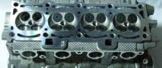
- The cylinder head is made of light aluminum alloy, its weight is relatively small, and between it and the cylinder block there is a special gasket that is not subject to shrinkage. The figure shows the structure of the BC head and valves.
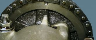
- The camshaft with sprocket and valve train, together with the chain, constitute the timing mechanism. The chain drive works together with the chain tensioner and damper.
- The flywheel is located at the rear pole of the crankshaft. The flywheel has a cast iron ring gear that meshes with the starter to start the engine. To increase engine power, you can reduce the weight of the flywheel by installing a lightweight version.
- The schematic diagram of the unit includes many others, for example, the engine lubrication diagram will also be presented, for example, this way:
In this diagram, without going into detail, you can see special channels and cavities in cast parts, the so-called lubrication passages and cavities for the circulation of coolant in the cylinder block.
It should be noted that the power of the unit cannot be maximum or close to it for a long time, without an adequate cooling and lubrication system.
In conclusion, it is worth noting that if you choose whether to choose a carburetor or an injector, then we can say that the first option is simpler and more reliable to repair, but the second is more modern and economical.
On the engine itself, the cylinder numbering goes from the location of the timing belt to the starter, that is, from left to right. The fourth cylinder is closest to the starter, and the first is closest to the timing belt. When connecting, it is important to look at which socket of the distributor cover the wire comes from, if you confuse their location, the car will not start.
interruptions in the operation of the engine of a VAZ 2108, VAZ 2109, VAZ 21099
During interruptions, the car engine idles unevenly, the engine does not develop sufficient power, and it consumes gasoline more. Engine failures on a VAZ 2108, VAZ 2109, VAZ 21099 are usually explained by incorrect carburetor adjustment, a faulty spark plug or one of the cylinders, or air leaks into one of the cylinders. It is necessary to find the fault and, if possible, eliminate it.
1. Start the engine of a VAZ 2108, VAZ 2109, VAZ 21099 car and leave the engine idling. Go to the exhaust pipe and listen to the sound of the exhaust. The sound should be even, “soft”, of the same tone. Popping sounds from the exhaust pipe at regular intervals indicate that one cylinder is not firing due to a failed spark plug, lack of spark at the plug, excessive air leakage into one cylinder, or a significant reduction in compression in the cylinder. Popping noises occur at irregular intervals due to improper carburetor adjustment, ignition, severe wear or dirty spark plugs. If popping noises occur at regular intervals, you can try to replace the entire set of spark plugs yourself, regardless of the mileage and appearance of the spark plugs, but it is better to do this after contacting a car service center to diagnose and adjust the carburetor and ignition system.
2. If the popping sounds are irregular, stop the engine and open the hood. Check the condition of the ignition system wires. High-voltage wires must not have insulation damage, and their tips must not be oxidized. If there is damage to the high-voltage wires, replace the faulty wire.
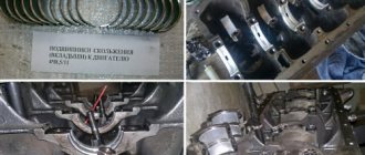
Lubricating parts
Combined engine lubrication device for the VAZ-2109 (2110). Oil is supplied to the main and connecting rod bearings, as well as to the camshaft supports under pressure; the cylinders, pistons, pins and rings, camshaft cams and pushers are lubricated by splashing; all other associated parts are lubricated by gravity.
A gear-type oil pump with a bypass valve is installed at the front of the block. The oil receiver is mounted using bolts on the cover of the second main bearing and the pump housing. The oil filter is non-separable and has bypass and anti-drainage valves. The design of the lubrication system and other engine systems is discussed in detail in separate articles.
Crankcase ventilation is forced, gases are removed through the oil separator.
The principle of operation of a four-stroke power plant
You can understand why it is important to connect high-voltage wires correctly if you study the principle of operation of the power plant. The carburetor or injector of the VAZ-2109 operates on approximately the same principle, since both power plants are four-stroke.
- First, the cylinder volume is filled with the fuel mixture and exhaust gases. This process is called "inlet".
- The engine then goes into compression. With it, the valves are closed, and the crankshaft and connecting rod move the piston upward. The mixture of fuel and air is transferred to the combustion chamber.
- During the expansion stage, the ignition is switched on and a spark appears. It ignites the fuel mixture, resulting in the formation of gases. They put pressure on the piston, causing it to move down. This force is transmitted through the connecting rod to the crankshaft.
- The process is completed by the “release” of exhaust gases through the exhaust system.
In order for the engine to operate smoothly and without jerking, the processes must take place in a certain order. This, first of all, concerns the order in which the cylinders are put into operation.
Finding the ignition moment in the ignition
On engine 402, ignition adjustment occurs according to the following algorithm and order:
- The crankshaft occupies a spatial position corresponding to 5 degrees of advance in ignition of the fuel mixture;
- This position can be easily achieved by aligning the mark on the pulley with the recess on the motor block;
- The coincidence means that the power plant has marked the end of a full piston stroke.
With the distribution sensor removed, adjustments are made as follows:
- I remove the spark plug from the head of the combustion chamber of the cylinder, which is listed as No. 1 in the order of fuel ignition;
- I cover it with a sheet of paper and turn the engine crankshaft;
- The air pushed out by the piston blows off the sheet, which indicates that it has reached the vertical maximum, from which the stroke begins;
- Then, using the keys, I set the octane corrector scale to 0.
Engine workflow through cylinders
The cylinders are activated as follows:
- In the first there is an upward movement. The gases expand and the mixture of air and fuel burns.
- In the third, to carry out the compression procedure, the piston rises.
- In the fourth, “injection” occurs - the piston moves down and at the same time a mixture of air and gasoline enters the cylinder.
- In the second cylinder, the piston rises and takes the upper position so that gases escape through the valve system. After which the exhaust gases are removed from the power unit.
Based on the principle of operation of the cylinders, their activation diagram looks like this: 1-3-4-2. It is important to connect them correctly so that the cylinders work in that order.
How to connect wires correctly
When replacing high-voltage conductors, they are first connected to the ignition distributor. The distributor cover is convenient in that it is always installed in one position. There is a special mark on it, thanks to which it will not be difficult to place the part in place. Before connecting the wires, inspect the cover. It must be intact, since if cracks appear, the performance of this unit is not guaranteed.
The mark on the distributor cover is located next to the wire socket of the first cylinder. The firing order of the cylinders is slightly out of order (1-3-4-2) due to the ignition slider. It moves around the circle (distributor) counterclockwise. It is precisely by this principle of movement of the slider that it is easy to remember the order of the wires. They need to be connected to carburetor and injection VAZ-2109 according to the same principle. On the distributor cover, connect the wires according to the principle of movement of the slider, this is the only way you can set the ignition correctly:
- the socket of the first cylinder is located at the mark;
- the third one is connected at the very bottom;
- on the same line with the socket of the first, there is a place for the wire to the 4th cylinder;
- at the top point the second cylinder is connected.
Valve location
In the VAZ-2109 model, the designers changed the previously familiar system with a camshaft chain drive.
Despite the simplicity of the old design, it was noisy and required additional adjustments after a short period of time. In the nines, the shape of the upper part of the piston was changed, and special recesses were added for the valves.
An important adjustment task is also to align the camshaft and crankshaft on the same axis so that they rotate together.
The intake and exhaust valves are located in a certain order, this should be taken into account when adjusting
When adjustment is necessary
Valve adjustment is required when problems occur with the engine or after passing a technical inspection. Experienced car owners can quite accurately determine the cause of a power unit malfunction; the main signs are the following:
Valve adjustment is also required after every 25-30 thousand kilometers . During this time, some parts wear out and structural gaps increase. Diagnostics can be done at a service center; this service is inexpensive.
Preparatory work
From the adjustment tool you will need:
- set of wrenches;
- special device for adjustment;
- measuring probe;
- several adjusting washers;
- screwdriver;
- tweezers;
- valve cover gaskets.
Before starting the repair, set the car to the handbrake and engage any gear. One of the front wheels must be suspended so that the crankshaft can turn easily.
The procedure is as follows:
- Raise the hood.
- Disconnect all pipes from the cover.
- Remove the windshield wiper housing.
- We unscrew the spark plugs.
- Remove the front timing belt cover.
Tip: To monitor the current position of the piston, you need to use the viewing window.
For many VAZ models, the adjustment technology is not much different. Those who have already had experience of working with previous versions will find it easy to understand. The gaps are set according to the order in which the cylinders operate. The exhaust valves are 1, 4, 5 and 8 when counted from the camshaft drive belt. We use the following table in our work:
We use the table to correctly determine the cylinder number based on the crankshaft position
Tip: Before starting the adjustment, it is worth placing additional marks on the pulley every 90 degrees.
- Before adjustment, it is necessary to align the piston of the first cylinder. To do this, turn the crankshaft so that the marks on the pulley and the rear belt cover coincide.
The marks on the timing belt pulley and rear cover must be at the same level - Using a 17 key, turn the camshaft 3 teeth clockwise. This is necessary so that the camshaft cams move away from the pushers.
We install the camshaft so that the fists move away from the pushers - We test the gaps with an adjustment feeler; the tool should move under the influence of slight forces.
Using a feeler gauge, determine the amount of clearance on the first cylinder
If the gaps are increased or decreased, the following actions must be taken:
- We install the adjustment device on the bearing housing.
Installing the adjustment device - Turn the pusher towards you.
- Using the lever, we fix the pusher in the desired position.
We press the pusher using the lever and fix it in this position - Use long tweezers to remove the old washer.
Using tweezers, remove the old adjusting washer
The next task is to select a new washer of optimal thickness. Calculating this parameter is simple; we use the formula below:
- H = A + (B – C), where
- H – thickness of the new washer,
- A – thickness of the removed washer,
- B – gap size,
- C is the required gap.
Install a new washer and remove the retainer. We check the gap with a feeler gauge and, if necessary, select another washer of the required thickness. The finished set of washers contains products with a pitch of 0.05 mm. This procedure is carried out for each engine cylinder.
Features of modifications with an injector or carburetor
A considerable part of the owners of the VAZ-2109 model are equipped with an injector. When adjusting here, one important fact should be taken into account - thermal expansion.
When the engine is running, metal parts increase slightly in size, which leads to a decrease in clearances. Therefore, adjustments must be made only on a cold engine.
This way you can correctly measure the gap and select the adjusting washer.
Block head and timing device
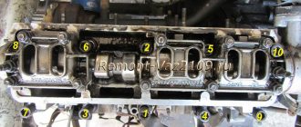
All front-wheel drive cars of the VAZ family, be it 2109, 2110 or 2114, have one cylinder head, common to all cylinders. They are mounted to the block using ten screws. During installation, a metal gasket is placed under it. This gasket is for single use and cannot be reused. There are five camshaft bearings at the top of the cylinder head.
The camshaft of the engine of the VAZ-2109 car has the index 21083. Some engines are equipped with 2110 or 2111 shafts; their design is slightly different from 21083, which allows for an increase in engine power. The shaft is cast from cast iron, there are five supports and eight cams on it that open the valves. It is driven by a toothed belt from the crankshaft pulley. The shafts can be correctly installed relative to each other using the alignment lug on the rear timing belt cover and the marks on the drive gears and flywheel.
Seats are pressed into the cylinder head, as well as valve guides. On the inside of the bushings there are grooves for supplying lubricant; the bushings are closed on top with oil deflector caps.
The valves are made of steel, and the intake head is made of heat-resistant steel. They are mounted obliquely in one row. The inlet valve has a larger diameter than the outlet valve. The gaps between the valves and camshaft cams are adjusted using shims that have increased wear resistance.
Pushers are metal cups moving in the cylinder head holes. To improve wear resistance, the surface in contact with the ends of the valve stems is cemented.
The procedure for connecting high-voltage wires VAZ
First, let's decide which of the four cylinders is first?
The first cylinder in front-wheel drive VAZs is located closer to the timing belt. If you look at the engine from the front, the first cylinder is the leftmost). And then everything is simple - from left to right - 1, 2, 3, 4.
In rear-wheel drive VAZ Classic and Niva, the first cylinder is located closer to the front bumper of the car.
General tips for connecting high-voltage wires
Checking high-voltage wires. To check the wires, you will need a multimeter tester. Check the resistance of the wires - it should be no more than 20 KOhms (in practice, the longest wire of cylinder 1 has a resistance of up to 10 KOhms).
If the wire resistance is more than 20 Kom, it must be replaced. Carefully inspect the wires for chafing on parts of the motor or other wires. In case of significant abrasion, replace the wire.
In case of minor abrasion, it is possible to lay the wire so that it does not rub and fix it in this position.
Laying wires. Do not try to connect the wires in a bundle. Disassemble the wiring harnesses, release the wires from the plastic holders. Connect the high-voltage leads to the corresponding cylinder spark plugs.
Lay the wires so that they do not rub against each other, engine parts, or hoses. Avoid sharp bends and tension on the wires.
After connecting all the wires, secure them into the bundle with special comb holders included in the delivery kit.
The procedure for connecting I/O wires to a VAZ carburetor (2108, 2109, 21099)
- The central wire from the distributor cover always goes to the ignition coil (bobbin).
- The outlet of the distributor cover, which faces towards the front of the car, is connected to the first cylinder.
- The outlet of the distributor cap, looking down, is connected to the third cylinder.
- The outlet of the distributor cap, looking rearward, is connected to the fourth cylinder.
- The outlet of the distributor cap, looking up, is connected to the second cylinder.
- The procedure for connecting high-voltage wires to a VAZ Classic, Niva with a carburetor and distributor.
Central wire from the ignition coil (bobbin)
1 cylinder - above the vacuum corrector. Next, clockwise, the order is 1-3-4-2.
Injection VAZ produced before 2004 with an old-style ignition module (4-pin low-voltage connector)
Actually, on the module body it is already indicated which cylinder the pins correspond to - but we duplicated them in red in case the module gets completely dirty, and you might not be able to see it in the photo.
Injection VAZ produced after 2004 with a new ignition coil (3-pin low-voltage connector)
As with the old-style ignition modules, the new coils are also marked with pins corresponding to the cylinders. But the connection order is different from the order on the old-style ignition module. Be careful.
The procedure for connecting high-voltage wires on a VAZ 2109 (carburetor, injector)
The ignition module on injection VAZ 2109 is deservedly considered one of the most complex electrical components. If the injectors have a module, then the carburetors have the simplest coil.
The actual, but incredibly important task of the module is the generation of high voltage current, which can reach 30 thousand watts. The current follows high-voltage wires to the spark plugs, which create a spark to ignite the air-fuel mixture.
The classic ignition coil is one of the components of the module, so the system works on a much more complex principle than on carburetors.
High voltage wires
Often, the main difficulty when repairing a carburetor VAZ 2109 is the reconnection of high-voltage wires that were previously disconnected from the distributor cover. It's also an ignition distributor.
The difficulty is that many people forget the connection procedure or simply do not know. But in practice, returning high-voltage wires is much easier than understanding the ignition module used on the injection VAZ 2109.
By following a few simple rules, you can easily return the wires to their rightful places.
- The ignition distributor cover is installed in its place, that is, on the distributor, only in a single position. Therefore, even if you wanted to, you won’t be able to confuse anything here. Otherwise the lid simply won't fit.
- There is an installation mark on the cover, which indicates the location of the wire socket from the first cylinder.
- The wires must be connected in the following sequence - 1, 3, 4, 2. Move counterclockwise when looking at the distributor cover from the side of the expansion tank.
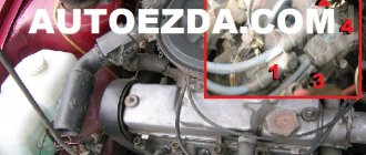
If for some reason there are no installation marks on the VAZ 2109 carburetor distributor cover, just follow the connection principle shown in the image.