The ignition module on injection VAZ 2109 is deservedly considered one of the most complex electrical components. If the injectors have a module, then the carburetors have the simplest coil.
The actual, but incredibly important task of the module is the generation of high voltage current, which can reach 30 thousand watts. The current follows high-voltage wires to the spark plugs, which create a spark to ignite the air-fuel mixture.
The classic ignition coil is one of the components of the module, so the system works on a much more complex principle than on carburetors.
The principle of operation of a four-stroke power plant
You can understand why it is important to connect high-voltage wires correctly if you study the principle of operation of the power plant. The carburetor or injector of the VAZ-2109 operates on approximately the same principle, since both power plants are four-stroke.
- First, the cylinder volume is filled with the fuel mixture and exhaust gases. This process is called "inlet".
- The engine then goes into compression. With it, the valves are closed, and the crankshaft and connecting rod move the piston upward. The mixture of fuel and air is transferred to the combustion chamber.
- During the expansion stage, the ignition is switched on and a spark appears. It ignites the fuel mixture, resulting in the formation of gases. They put pressure on the piston, causing it to move down. This force is transmitted through the connecting rod to the crankshaft.
- The process is completed by the “release” of exhaust gases through the exhaust system.
In order for the engine to operate smoothly and without jerking, the processes must take place in a certain order. This, first of all, concerns the order in which the cylinders are put into operation.
Cost and articles
Below are prices and articles for good and high-quality high-voltage wires for VAZ cars, both for 16 and 8 valve engines.
| Manufacturer | Number of valves | vendor code | Price, (rubles) |
| Standard | 16 | 21120-3707080-81 | 990 |
| SLON | 16 | 2112-3707080 | 1450 |
| VOLTON | 16 | VLT-2112005 | 915 |
| TESLA | 16 | Т516M | 1710 |
| LADA | 8 | 21110-3707080-82 | 695 |
| TESLA | 8 | Т514M | 875 |
| Standard | 8 | T684H | 620 |
| Original | 8 | 21110-3707080-12 | 710 |
Engine workflow through cylinders
The cylinders are activated as follows:
- In the first there is an upward movement. The gases expand and the mixture of air and fuel burns.
- In the third, to carry out the compression procedure, the piston rises.
- In the fourth, “injection” occurs - the piston moves down and at the same time a mixture of air and gasoline enters the cylinder.
- In the second cylinder, the piston rises and takes the upper position so that gases escape through the valve system. After which the exhaust gases are removed from the power unit.
Based on the principle of operation of the cylinders, their activation diagram looks like this: 1-3-4-2. It is important to connect them correctly so that the cylinders work in that order.
How to connect wires correctly
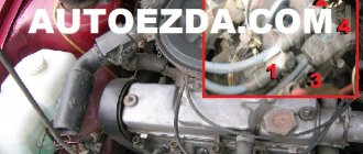
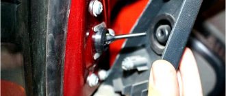
When replacing high-voltage conductors, they are first connected to the ignition distributor. The distributor cover is convenient in that it is always installed in one position. There is a special mark on it, thanks to which it will not be difficult to place the part in place. Before connecting the wires, inspect the cover. It must be intact, since if cracks appear, the performance of this unit is not guaranteed.
The mark on the distributor cover is located next to the wire socket of the first cylinder. The firing order of the cylinders is slightly out of order (1-3-4-2) due to the ignition slider. It moves around the circle (distributor) counterclockwise. It is precisely by this principle of movement of the slider that it is easy to remember the order of the wires. They need to be connected to carburetor and injection VAZ-2109 according to the same principle. On the distributor cover, connect the wires according to the principle of movement of the slider, this is the only way you can set the ignition correctly:
- the socket of the first cylinder is located at the mark;
- the third one is connected at the very bottom;
- on the same line with the socket of the first, there is a place for the wire to the 4th cylinder;
- at the top point the second cylinder is connected.
On the engine itself, the cylinder numbering goes from the location of the timing belt to the starter, that is, from left to right. The fourth cylinder is closest to the starter, and the first is closest to the timing belt. When connecting, it is important to look at which socket of the distributor cover the wire comes from, if you confuse their location, the car will not start.
If you have connected the wires correctly, but the car still does not start, then the problem may be in them. Check high-voltage conductors for integrity. If you haven't changed them in a while, it's worth buying a new set. The peculiarity of these wires is that over time microcracks can form on their surface. They lead to a lack of spark when the ignition distribution system is working. Moisture and dust get into these cracks, which damages the wire from the inside, although it appears intact from the outside.
Kiel Blinton 05.12.2010 - 17:56
Good day everyone! Forgive me if the topic is button accordion, but there is no one else to ask. Question - I have an engine 2110 engineer, I bought high-voltage wires and foolishly removed the old ones, but I didn’t remember the connection sequence. If I am facing the car, then the numbering of the candles is 1 2 3 4? But how do they all connect to the square ignition module? If anyone knows, please explain or draw a diagram, please.
Attached images
Post edited by Kiel Blinton: 12/05/2010 - 18:03
Website about joints
The ignition module on injection VAZ 2109 is deservedly considered one of the most complex electrical components. If the injectors have a module, then the carburetors have the simplest coil.
The actual, but incredibly important task of the module is the generation of high voltage current, which can reach 30 thousand watts. The current follows high-voltage wires to the spark plugs, which create a spark to ignite the air-fuel mixture.
The classic ignition coil is one of the components of the module, so the system works on a much more complex principle than on carburetors.
Sereshka 05.12.2010 - 18:01
Kiel Blinton (05.12.2010 - 17:56)
:
Good day everyone! Forgive me if the topic is button accordion, but there is no one else to ask. Question - I have an engine 2110 engineer, I bought high-voltage wires and foolishly removed the old ones, but I didn’t remember the connection sequence. If I am facing the car, then the numbering of the spark plugs is 1 2 3 4. But how are they all connected to the square ignition module? If anyone knows, please explain or draw a diagram, please.
There should be numbers on the module itself.
High voltage wires
Often, the main difficulty when repairing a carburetor VAZ 2109 is the reconnection of high-voltage wires that were previously disconnected from the distributor cover. It's also an ignition distributor.
The difficulty is that many people forget the connection procedure or simply do not know. But in practice, returning high-voltage wires is much easier than understanding the ignition module used on the injection VAZ 2109.
By following a few simple rules, you can easily return the wires to their rightful places.
- The ignition distributor cover is installed in its place, that is, on the distributor, only in a single position. Therefore, even if you wanted to, you won’t be able to confuse anything here. Otherwise the lid simply won't fit.
- There is an installation mark on the cover, which indicates the location of the wire socket from the first cylinder.
- The wires must be connected in the following sequence - 1, 3, 4, 2. Move counterclockwise when looking at the distributor cover from the side of the expansion tank.
If for some reason there are no installation marks on the VAZ 2109 carburetor distributor cover, just follow the connection principle shown in the image.
Functionality check
To accurately determine whether it is time to change the high-voltage wires of the VAZ, you need to check their performance with a multimeter.
This operation will take you no more than 15 minutes:
- Turn off the ignition;
- We remove the wires: disconnect the first end from the ignition module, the second from the cylinder;
- We switch the tester to ohmmeter mode and connect the multimeter probes to the wire contacts.
If the high-voltage wires on the VAZ 2114 are in normal technical condition, the multimeter will show a resistance within the value indicated on the wire insulation; if the readings are different, the armored wires on the VAZ 2114 need to be replaced. The process must be repeated on each wire in turn.
If the test shows disappointing results, there is a possibility that the problem of increased resistance lies in oxidized contacts. In this case, you can try to revive the VVP by wiping the contacts with VD-40 or carburetor cleaning fluid.
Also, the cause of problems with ignition can be a breakdown of the GDP. You can determine it visually in the dark - take a flashlight and open the hood of the fourteenth, find and inspect the armored wires, if you notice a slight spark on the insulation - the air intakes are broken and need to be replaced.
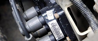
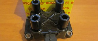
Features of the ignition module
Now let's talk about a more complex issue - the ignition module and its design features.
The design includes several components, each of which has its own nuances.
Component
Peculiarities
There are always two coils on a VAZ 2109. This mechanism is responsible for generating current
Switch keys also work together. Through them, the current goes to the spark plugs, plus the controller regulates the time the current is turned on, which is calculated by receiving information from the crankshaft sensor
Electronic control unit
Responsible for distributing information in the form of electronic impulses
High-strength plastic is used for its manufacture, which largely ensures the durability and reliability of the device.
Ignition coil
Location
Any work related to repair, testing, and maintenance of the ignition module will be impossible to perform if you do not know basic things - the location of the device.
You can find the ignition module (ignition module) in the engine compartment. Find the high voltage wires that go to the spark plugs. One end is connected to them, and the other goes to the module. The MZ is small in size and enclosed in a plastic housing.
Device location
Principle of operation
Initially, on carburetor cars, the system worked due to the presence of an ignition coil. With injectors everything is somewhat different.
- Initially, the ignition coil is turned on, generating a high voltage current. The coil operates on the principle of magnetic induction;
- Then the electronic control unit MZ is connected to the work, performing the functions of control, transmitting commands, and ensuring the flow of current required by the characteristics to the spark plugs;
- Next, the spark plugs activate the spark, ignition occurs, and so on.
MH malfunctions
The ignition module often shows the most basic sign of failure - lack of spark. But this is not the only indicator of a malfunction. These also include:
- Lack of dynamics when accelerating the car. Trying to quickly pick up speed, you can clearly feel failures in engine operation;
- The engine does not produce the usual power; in some cases, the engine is not able to pull the car uphill;
- The idle speed fluctuates;
- One of the pairs of engine cylinders refuses to work. Here, most likely, there is no current that should come from the ignition coil.
To eliminate problems with the MH, the first thing you need to do is check the spark plugs, and then make sure the other elements are working.
Purpose of the distributor cover
The design of the ignition distributor cap (aka distributor) has remained and remains virtually unchanged throughout the entire history of the use of this device as part of the ignition system of gasoline engines:
- On most ignition caps, the contacts for the spark plug wires are marked with numbers that correspond to the serial numbers of the corresponding cylinders
- In addition to protecting the distributor mechanism itself from moisture and dirt, it also serves the purpose of alternating the supply of high-voltage current from the ignition coil winding through high-voltage wires to the spark plugs
- It is because of this narrow specialization that the distributor cap has undergone almost minimal changes along the evolution of all car systems
Let's look at the design and operating principle of this much-needed part.
The distributor cap is a molded part made of non-electrically conductive material (insulator) that has the following device:
- Metal contacts are pressed into this part - these are the side and central electrodes
- The number of side electrodes strictly corresponds to the number of engine spark plugs (but not cylinders, do not forget that there are engines in which there is more than one spark plug for each individual cylinder); the distributor cover on the VAZ 2109 in our case has four side electrodes
- A high-voltage (armor) wire coming from the ignition coil is connected to the central electrode from the outside
- To the side electrodes - high-voltage (armor) wires going to the spark plugs
- Inside the cover itself there is a central contact equipped with a terminal that has a spring-loaded contact element (“carbon”), which transmits voltage to the central (main) contact of the distributor rotor (ignition distributor)
The procedure for connecting high-voltage armored wires to the cover on a VAZ 2108-21099
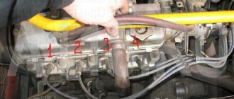
In the process of repairing a car, sometimes it is necessary to disconnect the armor wires from the distributor (see VAZ 2109 distributor device: the difference between contact and non-contact ignition systems and adjusting the ignition timing), while disconnecting these wires, drivers often do not remember the order in which they were connected, which then causes problems with the ignition system, due to the incorrect order of these same wires. Don't despair, our instructions will remind you:
- We list the conditions for correctly connecting the armored wires to the distributor cap:
- It should be remembered that the distributor cover can be installed on the distributor itself in one fixed position; it is simply impossible to confuse anything here
- There is a special installation mark on the cover that will tell you the socket of the wire going to the first cylinder
- The wires are connected to it in the sequence: first, third, fourth, second (we mean the cylinder) in a counterclockwise direction, as if we are looking at this cap from the side where the expansion tank is located.
- To make it clearer, the photo below shows the correct order for connecting the armor wires from the cylinders to the cover
Correct order of connecting armor wires
Now you can connect the armor wires correctly with your own hands.
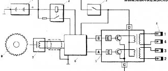
General diagram of the electrical equipment of the VAZ-2114
Before proceeding directly to the circuits and ignition wires, it is necessary to have knowledge of the general structure of the electrical equipment of the VAZ-2114. To do this, consider the general standard technical diagram provided by the manufacturer, with an explanation:
Each color of the wire on the diagram and in the car corresponds. Therefore, looking at the device, you can easily determine where to connect which one. But, even with a diagram, many motorists are confused about this issue. Based on this, we can conclude that if nothing is clear, then you should contact professionals who will understand the wiring pinout and connect everything quickly and efficiently.
Injector connection diagram
It is quite difficult to describe in words the pinout of the wires connecting the injector to the ignition system, so you should pay attention to the diagram below.
General electrical circuit of the injector