Modern Lada model
Like any modern foreign car, the Lada Priora has many different sensors installed. The condition of important vehicle systems depends on their correct operation. The problem is that if some sensors fail, the Priora can continue to move. Faults of this kind can lead to increased fuel consumption, unstable engine operation, and increased wear of parts, but the car will drive, and you will only find out about the fault when it means you have to make expensive repairs.
In order not to go into the engine compartment with a multimeter, the Priora has a controller that allows you to check faults using a special tester, a plug-in or built-in on-board computer. In order to diagnose the systems, just press 2 buttons and look at the error codes.
Self-diagnosis using BC
The owner can identify the main error codes of Priora 8 and 16 valves using the built-in controller and on-board computer (BC), without resorting to the services of car service diagnosticians. To do this, you must activate the vehicle testing option. The arrows on the instrument panel move to the maximum possible position. Further manipulations are performed in the following sequence:
- The ignition is turned off and the daily mileage reset button is activated. Then the ignition is turned on again with the button held down;
- After this, all the icons on the instrument panel should light up, and the arrows of the control devices should begin to move from zero to maximum values. This behavior indicates the normal functioning of all sensors;
- On the right steering wheel switch there is a key for selecting BC functions. After pressing it, information about the software category will appear on the display;
- You should press this button again, combinations of problems will be displayed on the monitor. If necessary, error information is also reset here. To do this, hold down the mileage reset button for a few seconds.
Installation
Replacing the old instrument panel without CAN with a dashboard with navigation without CAN (2170-3801010-50) is carried out without modifications. We remove the old panel and install a new one in its place, insert the connector with wires, connect the antenna (we fix it on the roof) and, if necessary, change the right steering column switch.
If the old instrument cluster without navigation, but with CAN, and instead of it it is planned to install a new dashboard with navigation with CAN (2170-3801010-60), then you need to rearrange contacts 10-11 to 28-29 (if after connecting it still does not work, change 28 and 29 places).
After installing the new instrument panel, the mileage will be reset to zero.
Code meanings for self-diagnosis
Using the on-board computer, the driver can determine the following faults:
- Code “ 2
” – excessive voltage in the on-board network. To eliminate it, you need to check the main electrical circuits; - The number “ 3
” indicates a malfunction of the fuel control indicator; - «4
» – problems with the refrigerant temperature sensor; - The number “ 5
” means incorrect operation of the environmental indicator; - Code “ 6
” means engine overheating; - «7
» – critical lubricant pressure; - The number “ 8
” indicates a malfunction in the brake system; - «9
» – signals that the battery is low; - The " E
" symbol indicates a problem with the packet data.
It is worth noting that if the BC options switch key is inactive for more than 10 seconds, the instrument panel will return to normal operation.
VAZ errors and their solutions
Owners of domestic cars can easily find a problem with their car. This became possible thanks to the use of on-board computers and the introduction of modern equipment diagnostic tools. This article will describe in detail the errors and how to eliminate them in VAZ 2110, 2112, 2114, Kalina, Priora and how to eliminate them.
How to diagnose a car yourself
Do not rush to go to the service center. Although specialists use test benches to detect malfunctions, and their diagnostics are more accurate, every car owner is still able to find out the cause of the problem using information about the error codes of the on-board computer.
To view error codes recorded by the controller:
- Sit behind the wheel, then press and hold the odometer button. It is located at the bottom of the dashboard.
- Turn the key in the lock to position “1”. While turning the key, release the button. This will be followed by a quick set of readings on the instruments.
- After this, press the button again: the display will show the controller firmware version.
- Finally, press the button the last, third time to display the VAZ controller errors.
VAZ error codes:
- P0030 - Oxygen sensor heater before the converter, control circuit open
- P0031 - Oxygen sensor heater before the converter, control circuit short to ground
- P0032 - Heater of the oxygen sensor to the converter, short circuit of the control circuit to the board. net
- P0036 - Oxygen sensor heater after the converter, control circuit open
- P0037 - Oxygen sensor heater after the converter, control circuit short to ground
- P0038 - Heater of the oxygen sensor after the converter, short circuit of the control circuit to the board. net
- P0102 - Mass air flow sensor circuit, low signal level
- P0103 - Mass air flow sensor circuit, high signal level
- P0112 - Air temperature sensor circuit, low signal level
- P0113 - Air temperature sensor circuit, high signal level
- P0116 - Coolant temperature sensor circuit, signal out of acceptable range
- P0117 - Coolant temperature sensor circuit, low signal level
- P0118 - Coolant temperature sensor circuit, high signal level
- P0122 - Throttle Position Sensor Circuit Low Signal
- P0123 - Throttle Position Sensor Circuit High Signal
- P0130 - The oxygen sensor before the converter is faulty
- P0131 - Oxygen sensor circuit to converter, low output level
- P0132 - Oxygen sensor circuit to converter, high output level
- P0133 - Oxygen sensor circuit to the converter, slow response to changes in mixture composition
- P0134 - The oxygen sensor circuit to the converter is inactive
- P0136 - The oxygen sensor after the converter is faulty
- P0137 - Oxygen sensor circuit after the converter, low signal level
- P0138 - Oxygen sensor circuit after the converter, high signal level
- P0140 - The oxygen sensor circuit after the converter is inactive
- P0141 - Oxygen sensor after the converter, heater is faulty
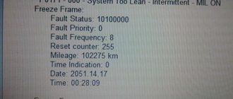
- P0171 - Fuel supply system too lean
- P0172 - Fuel system too rich
- P0201 - Cylinder 1 injector, control circuit open
- P0202 - Cylinder 2 injector, control circuit open
- P0203 - Cylinder 3 injector, control circuit open
- P0204 - Cylinder 4 injector, control circuit open
- P0217 - Engine temperature is higher than permissible
- P0230 - Fuel pump relay circuit malfunction
- P0261 - Cylinder 1 injector, control circuit short to ground
- P0263 - Injector driver fault 1
- P0264 - Cylinder 2 injector, control circuit short to ground
- P0266 - Faulty injector driver 2
- P0267 - Cylinder 3 injector, control circuit short to ground
- P0269 - Injector 3 driver malfunction
- P0270 - Cylinder 4 injector, control circuit short to ground
- P0262 - Cylinder 1 injector, control circuit shorted to on-board network
- P0265 - Cylinder 2 injector, control circuit shorted to on-board network
- P0268 - Cylinder 3 injector, control circuit shorted to on-board network
- P0271 - Cylinder 4 injector, control circuit shorted to on-board network
- P0272 - Faulty injector driver 4
- P0300 - Random/multiple misfires detected
- P0301 - Cylinder 1, misfire detected
- P0302 - Cylinder 2, misfire detected
- P0303 - Cylinder 3, misfire detected
- P0304 - Cylinder 4, misfire detected
- P0326 - Knock sensor circuit, signal output out of acceptable range
- P0327 - Knock sensor circuit low signal
- P0328 - Knock sensor circuit, high signal level
- P0335 - Crankshaft position sensor circuit is faulty
- P0336 - Crankshaft position sensor circuit, signal out of acceptable range
- P0337 - Crankshaft position sensor, short to ground
- P0338 - Crankshaft position sensor, open circuit
- — Malfunction of the camshaft position sensor
- P0342 - Phase sensor circuit, low signal level
- P0343 - Phase sensor circuit, high signal level
- P0346 - Phase sensor circuit, signal output out of acceptable range
- P0351 - Ignition coil of cylinder 1 (1-4), control circuit open
- P0352 - Ignition coil of cylinder 2 (2-3), control circuit open
- P0353 - Ignition coil of cylinder 3, control circuit open
- P0354 - Ignition coil of cylinder 4, control circuit open
- P0363 - Misfire detected, fuel supply to idle cylinders is turned off
- P0422 - Neutralizer efficiency below threshold
- P0441 - Gasoline vapor recovery system, incorrect air flow through the canister purge valve
- P0444 - Canister purge valve, control circuit open
- P0445 - canister purge valve, control circuit short to ground or on-board network
- P0480 - Fan relay, control circuit open
- P0481 - Cooling fan 2 circuit malfunction
- P0500 - Vehicle speed sensor is faulty
- P0506 - Idle system, low engine speed
- P0507 - Idle system, high engine speed
- P0511 - Idle speed control, control circuit faulty
- P0560 - On-board network voltage is below the system operability threshold
- P0562 - On-board voltage, low level
- P0563 - On-board voltage, high level
- P0601 - Engine control system controller, ROM checksum error
- P0615 - Additional starter relay, control circuit open
- P0616 - Additional starter relay, control circuit short to ground
- P0617 - Additional starter relay, control circuit shorted to on-board network
- P0627 - Fuel pump relay, control circuit open
- P0628 - Fuel pump relay, control circuit short to ground
- P0629 - Fuel pump relay, control circuit shorted to on-board network
- P0645 - Air conditioning compressor clutch relay, control circuit open
- P0646 - Air conditioning compressor clutch relay, control circuit short to ground
- P0647 - Air conditioning compressor clutch relay, control circuit shorted to board. net
- P0650 - Malfunction indicator lamp, control circuit faulty
- P0654 - Instrument cluster tachometer, control circuit faulty
- P0685 - Main relay, control circuit open
- P0686 - Main relay, control circuit short to ground
- P0687 - Main relay, control circuit shorted to on-board network
- P0691 - Fan relay, control circuit short to ground
- P0692 - Fan relay, control circuit shorted to on-board network
- P1102 - Oxygen Sensor Heater Resistance Low
- P1115 - Faulty oxygen sensor heating circuit
- P1123 - Rich mixture at idle
- P1124 - Lean mixture at idle
- P1127 - Rich mixture at Partial Load
- P1128 - Lean mixture in Partial Load mode
- P1135 - Oxygen sensor heater circuit 1 open, short circuit
- P1136 - Rich mixture in Light Load mode
- P1137 - Lean mixture in Light Load mode
- P1140 - Measured load differs from calculation
- P1141 - Post-converter oxygen sensor 1 heater malfunction
- P1171 - Low level CO potentiometer
- P1172 - High level CO potentiometer
- P1301 - Cylinder 1, misfire detected, critical for the converter
- P1302 - Cylinder 2, misfire detected, critical for the converter
- P1303 - Cylinder 3, misfire detected, critical for the converter
- P1304 - Cylinder 4, misfire detected, critical for the converter
- P1386 - Knock Channel Test Error
- P1410 - Canister purge valve control circuit short circuit to +12V
- P1425 - Canister purge valve control circuit short circuit to ground
- P1426 - Canister purge valve control circuit open
- P1500 - Fuel pump relay control circuit open
- P1501 - Short circuit to ground of the fuel pump relay control circuit
- P1502 - Short circuit to +12V fuel pump relay control circuit
- P1509 - Idle Air Control Circuit Overload
- P1513 - Idle air control circuit short circuit to ground
- P1514 - Idle air control circuit short circuit to +12V, open
- P1541 - Fuel pump relay control circuit open
- P1570 - Immobilizer, circuit faulty
- P1602 - Engine control system controller, power supply loss
- P1606 - Rough road sensor circuit, signal out of acceptable range
- P1616 - Rough Road Sensor Circuit Low Signal
- P1617 - Rough road sensor circuit, high signal level
- P2301 - Ignition coil of cylinder 1 (1-4), control circuit shorted to board. net
- P2303 - Ignition coil of cylinder 2 (2-3), control circuit shorted to board. net
- P2305 - Ignition coil of cylinder 3, control circuit shorted to board. net
- P2307 - Ignition coil of cylinder 4, control circuit shorted to board. net
We recommend: What to check before buying a car
Mass air flow sensor
- P0101 - Diagnosis of reality. Air flow is out of range
- P0102 - Low value diagnostics. The signal period is greater than the upper maximum permissible value
- P0103 - High value diagnostics. The signal period is less than the lower maximum permissible value
Intake air temperature sensor
- P0112 - Low value diagnostic. Voltage is less than the lower maximum permissible value
- P0113 - Diagnostics high value. Voltage is greater than the upper maximum permissible value
Coolant temperature sensor
- P0116 - Diagnosis of reality. Temperature is less than calculated value
- P0117 - Low value diagnostic. Voltage is less than the lower maximum permissible value
- P0118 - Diagnostics high value. Voltage is greater than the upper maximum permissible value
Throttle Position Sensors
- P2135 - Diagnostics of the mismatch between the signals of two sensors. The sensor voltages differ by the threshold value
- P0122 - Low value diagnostic (sensor 1). Voltage is less than the lower maximum permissible value
- P0123 - High value diagnostic (sensor 1). Voltage is greater than the upper maximum permissible value
- P0222 - Low value diagnostic (sensor 2). Voltage is less than the lower maximum permissible value
- P0223 - High value diagnostic (sensor 2). Voltage is greater than the upper maximum permissible value
Accelerator pedal position sensors
- P2138 - Diagnostics of the mismatch between the signals of two sensors. The sensor voltages differ by the threshold value
- P2122 - Low value diagnostic (sensor 1). Voltage is less than the lower maximum permissible value
- P2123 - High value diagnostic (sensor 1). Voltage is greater than the upper maximum permissible value
- P2127 - Low value diagnostic (sensor 2). Voltage is less than the lower maximum permissible value
- P2128 - High value diagnostic (sensor 2). Voltage is greater than the upper maximum permissible value
Injectors
- P0201, P0202, P0203, P0204 - Diagnostics of open control circuit. Driver diagnostics
- P0261, P0264, P0267, P0270 - Diagnosis of control circuit short circuit to ground.
- P0262, P0265, P0268, P0271 - Diagnostics of a short circuit in the control circuit to the on-board network.
We recommend: Self-diagnosis of faults on the VAZ 2115
Control oxygen sensor
- P0130 - Signal circuit integrity diagnostics. Voltage is less than the lower maximum permissible value or greater than the upper maximum permissible value
- P0131 - Low value diagnostic. Voltage is less than the lower maximum permissible value
- P0132 - Diagnostics high value. Voltage is greater than the upper maximum permissible value
- P0133 - Slow Response Diagnosis. The signal period is greater than the maximum permissible value
- P0134 - Activity Diagnostics. Voltage is less than the upper maximum permissible value and greater than the lower maximum permissible value
- P0030 - Diagnostics of open circuit of the heater. Driver diagnostics
- P0031 - Diagnostics of a short circuit of the heater circuit to ground.
- P0032 - Diagnostics of a short circuit of the heater circuit to the on-board network.
Diagnostic oxygen sensor
- P0136 - Signal circuit integrity diagnostics. Voltage is less than the lower maximum permissible value or greater than the upper maximum permissible value
- P0137 - Low value diagnostic. Voltage is less than the lower maximum permissible value
- P0138 - Diagnostics high value. voltage is greater than the upper maximum permissible value
- P0140 - Activity Diagnostics. Voltage is less than the upper maximum permissible value and greater than the lower maximum permissible value
- P0036 - Heater circuit open circuit diagnostics. Driver diagnostics
- P0037 - Diagnostics of a short circuit of the heater circuit to ground.
- P0038 - Diagnostics of a short circuit of the heater circuit to the on-board network.
Fuel supply system
- P0171 - Diagnosis of poor mixture composition. Fuel correction coefficients are greater than the upper maximum permissible value
- P2187 - Diagnosis of poor mixture composition (at idle).
- P0172 - Diagnostics of the richness of the mixture. Fuel correction coefficients are less than the lower maximum permissible value
- P2188 - Diagnostics of the richness of the mixture (at idle).
- Engine overheating - P0217. Engine temperature monitoring
Misfire for toxicity
- P0300, P0301, P0302, P0303, P0304 - Diagnosis of the presence of misfires affecting toxicity. The number of misfires is greater than the maximum permissible value
Misfire to protect the converter
- P0363, P1301, P1302, P1303, P1304 - Diagnosis of the presence of misfires affecting the converter. The number of misfires is greater than the maximum permissible value
Knock sensor
- P0326 - Low value diagnostics. Normalized signal level is outside the acceptable range
- P0327 - Low value diagnostics. The normalized signal level is less than the lower maximum permissible value
- P0328 - High value diagnostics. The normalized signal level is greater than the upper maximum permissible value
Crankshaft position sensor
- P0335 - Signal presence diagnostics. Change in air flow in the absence of a signal from the crankshaft position sensor above the maximum permissible value
- P0336 - Diagnosis of reality. The controller counts the wrong number of teeth per revolution of the crankshaft
Camshaft position sensor
- P0340 - Diagnostics of signal presence. The sensor signal does not change when the engine is running
- P0342 - Low value diagnostics. Low sensor signal for several crankshaft revolutions
- P0343 - High value diagnostics. High sensor signal for several crankshaft revolutions
Ignition coils
- P0351, P0352 - Open circuit diagnostics. The primary circuit current is less than the maximum permissible value
- P2301, P2304 - Diagnostics of a short circuit to the on-board network. The primary circuit current is greater than the maximum permissible value
- Neutralizer - P0422. Determining the capacity of stored oxygen by comparing the amplitude range of the control and diagnostic oxygen sensors
Canister purge valve
- P0441 - Functional diagnostics. The response of the idle control system is greater or less than the maximum permissible value
- P0459 - Diagnostics of a short circuit to the on-board network. Driver diagnostics
- P0458 - Diagnostics of a short circuit to ground.
- P0444 - Open circuit diagnostics.
Cooling fan relay 1
- P0692 - Diagnostics of a short circuit to the on-board network. Driver diagnostics
- P0691 - Diagnostics of a short circuit to ground.
- P0480 - Open circuit diagnostics.
Cooling fan relay 2
- P0694 - Diagnostics of a short circuit to the on-board network. Driver diagnostics
- P0693 - Diagnostics of a short circuit to ground.
- P0481 - Open circuit diagnostics.
- Cooling fan - P0485. Diagnostics of cooling fan supply voltage
- Vehicle speed sensor - P0500. Signal presence diagnostics
- Brake pedal sensor - P0504. Diagnostics of sensor signal mismatch time
Onboard voltage
- P0560 - Diagnosis of value validity. voltage in circuits Cl. "30" and Cl. “15” differs by the threshold value
- P0562 - Low value diagnostic. Voltage is less than the lower maximum permissible value
- P0563 - High value diagnostic. Voltage is greater than the upper maximum permissible value
- P1602 - Supply voltage diagnostics. Power failure
Controller
- P1640 - EEPROM diagnostics. EEPROM test error
- P0601 - Software checksum diagnostics. Invalid checksum
- P0606 - Internal controller checks. ADC is faulty
- P2105 - The monitoring module is faulty.
Starter relay
- P0615 - Open circuit diagnostics. Driver diagnostics
- P0616 - Diagnosis of a short circuit to ground.
- P0617 - Diagnostics of a short circuit to the on-board network.
Fuel pump relay
- P0627 - Open circuit diagnostics. Driver diagnostics
- P0628 - Diagnosis of a short circuit to ground.
- P0629 - Diagnostics of a short circuit to the on-board network.
A/C clutch relay
- P0645 - Open circuit diagnostics. Driver diagnostics
- P0646 - Diagnostics of a short circuit to ground.
- P0647 - Diagnostics of a short circuit to the on-board network.
How to remove information about corrected errors from the controller memory
Sometimes, after troubleshooting, error messages remain in memory and periodically appear on the panel.
To clear an error code from memory:
- Write down and check for irrelevant codes that appear.
- Reset the daily mileage readings by pressing the corresponding button, after which the error code is guaranteed to be deleted from memory.
How to get rid of the "Check Engine" message
Sometimes drivers see a glowing orange icon at the bottom of the instrument panel. This is how the computer reports an engine malfunction. Self-diagnosis will not allow you to determine and correct the cause of the motor problem. However, the error often appears on serviceable cars. Therefore, to reset the problem code:
- Turn on the ignition, but do not start the car.
- Open the hood and use a wrench to loosen and remove the negative terminal on the battery.
- After a minute, return the terminal to its original position.
- Close the hood and turn the ignition key to position “0”.
- Turn the ignition back on and start the engine. After a short time the error should disappear.
We recommend: Maintenance
If the above instructions did not help, it is worth carrying out a more accurate diagnosis of the car at a service center in order to correct the problem at an early stage.
Checking with a plug-in tester
More accurate and comprehensive diagnostics can be performed using a connected computer or a special tester. However, the data displayed on the screen is alphanumeric. The letters have the following meaning:
- P
– errors in the operation of the electronic systems of the power unit; - C
– problems with the functioning of the chassis; - B
– electronic malfunctions in the cabin; - U
– joint system errors.
In addition, the number 0 means OBD code 2, numbers 1 and 2 indicate the enterprise code, and 3 is the backup password.
Basic ignition system
(the letter P precedes the digital designation):
- 0300
– no spark in the cylinders of 16 valves; - 0326
– defect or short circuit in the knock indicator circuit; - 0337
– difference of the crankshaft controller to ground; - 0343
– high level in the headlight sensor circuit 0342 – a similar low indicator; - 0422
– signaling device malfunction; - 0444, 0445
– failure of the adsorber valve; - 0480, 0481
– problems with the fan assembly.
Deciphering faults in the fuel and air systems
- P0030 - the oxygen sensor heater wire to the exhaust gas converter has broken;
- P0031 - the same electrical wire has shorted to ground;
- P0032 - the same wire has shorted to the on-board network (BS);
- P0036 - the wiring of the oxygen sensor heater is broken, after the converter;
- P0037 - the same wiring has shorted to ground;
- P0038 - it has shorted to BS;
- P0102 - weak signal in the mass air flow sensor network;
- P0103 - very strong signal in the network of this device;
- P0112 - weak signal in the air temperature sensor network;
- P0113 - very strong signal in the network of the same device;
- P0116 - antifreeze temperature sensor signal is out of operating range;
- P0117 - poor signal from the antifreeze temperature sensor network;
- P0118 - very strong signal from the antifreeze temperature sensor;
P0122 - poor signal in the throttle position sensor circuit;
- P0123 - very strong signal in the same circuit;
- P0130 - the oxygen sensor before the converter does not work;
- P0131 - weak outgoing signal on the network of this device;
- P0132 - signal too strong on the same network;
- P0133 - slow response to changes in mixture quality in the network of the same device;
- P0134 - oxygen sensor circuit inactive;
- P0136 - the oxygen sensor after the converter is broken;
- P0137 - poor signal in the circuit of this device;
- P0138 - signal too strong in the same circuit;
- P0140 - the same sensor circuit is inactive;
- P0141 - the oxygen sensor heater after the converter is broken;
- P0171 - there is a lot of air in the fuel mixture;
- P0172 - there is a lot of gasoline in the fuel mixture;
- P0201 - injector wire No. 1 is broken;
- P0202 - injector wire No. 2 is broken;
- P0203 - injector wire No. 3 is broken;
- P0204 - injector wire No. 4 is broken;
- P0217 - engine overheated;
- P0230 - failure in the electric fuel pump relay network;
- P0263 - injector driver No. 1 does not work;
- P0264 - the injector circuit of cylinder No. 2 has shorted to ground;
- P0266 - injector driver No. 2 does not work;
- P0267 - injector circuit No. 3 has shorted to ground;
- P0269 - injector driver No. 3 does not work;
- P0270 - injector circuit No. 4 has shorted to ground;
- P0262 - the injector circuit of cylinder No. 1 is shorted to the BS;
- P0265 - injector circuit No. 2 is shorted to BS;
- P0268 - injector circuit No. 3 is shorted to BS;
- P0271 - injector circuit No. 4 is shorted to BS;
- P0272 - injector driver No. 4 does not work.
Here we are looking for an electrical problem that has arisen.
P0261 - the injector circuit of cylinder No. 1 has shorted to ground;
Return to contents
Why does it occur: reasons
The reason for the appearance of the number on the display is rarely clear without a detailed analysis of the issue; there is only general information. But, according to the experts, the options are as follows:
- The greatest probability is due to a malfunction of the coolant temperature sensor.
- Further in descending order - the circuit with this sensor could break.
- Due to external influences (accident, shock, etc.), the control unit system sometimes malfunctions and generates an error.
- Plaque on the device may contribute to loss of contact.
Such reasons will not be a serious stumbling block to free travel, and will not make your wallet noticeably empty. Each of the points is completely solvable, both independently and at a service station, you just need to allocate time and a little effort for this.
Failures in the idle speed system (IAC) and ESC
- P0500 - speed sensor is broken.
- P0506 - very low engine speed at idle.
- P0507 - too high speed at idle.
- P0511 - the XX regulator network is faulty.
- P0560 - BS voltage is below the minimum threshold.
- P0562 - very low voltage in the BS.
- P0563 - very high voltage in the BS.
- P0601 - ROM checksum error.
- P0615 - the wires of the additional starter relay are broken.
- P0616 - the same wires are shorted to ground.
- P0617 - they shorted at the BS.
- P0627 - the fuel pump relay wires are broken.
- P0628 - the same wires are shorted to ground.
- P0629 - they shorted it to the BS.
- P0645 - break in the wiring of the air conditioning compressor clutch relay.
- P0646 - the same wiring has shorted to ground.
- P0647 - she shorted to BS.
- P0650 - Malfunction indicator light circuit does not operate.
- P0654 - Tachometer control circuit is faulty.
- P0685 - the main relay electrical wire is broken.
- P0686 - the same electrical wire has shorted to ground.
- P0687 - he shorted it to the BS.
- P0691 - the electrical wiring of the fan control relay is shorted to ground.
- P0692 - the same wiring has shorted to the BS.
Note: in cases where the computer displays error codes that indicate a break in the electrical wiring of a device, before troubleshooting the problem and purchasing spare parts, you must first see if the electrical wiring plug has come out of the connector of the corresponding device. Such incidents happened. Testers and computers are, of course, good, but nothing can replace the eyes of a car enthusiast. Good luck with the repair.
I replaced the DTOZH, the error is still on, where can I look for the cause?
- The parking light indicator of the VAZ Priora is flashing on the instrument panel - 10 answers
- How to solve “error 4” in Priora? – 6 answers
- Error 789E on Priora – 4 answers
- What could cause an error - a malfunction of the knock sensor on a Priora? – 4 answers
- The check light came on after cleaning the throttle on a Priora - 3 answers
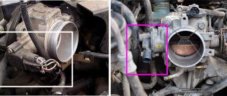
That's right, it should ring in several places 17, 34, 35. The signal is orange at pin 39. Diagram
Replace the terminal. The one that fits onto the sensor. If it's old and dirty. If not, then tighten it up. If it doesn’t help, connect the wire from the sensor to the panel.
Thanks for the answer, I will try your options.
Don’t you have two DTOZh sensors, one for the control unit and one for the control unit? You could replace the one on the ECU. When you remove the terminal from it, is it reflected on the instrument panel?
It is not displayed on the panel when I remove the terminal, I remove the terminal from the battery and then put it back in place, the error is not displayed, I drove 15 kilometers and the check light comes on, error 4, which means a malfunction in the coolant temperature sensor system.
LADA 2170 Priora
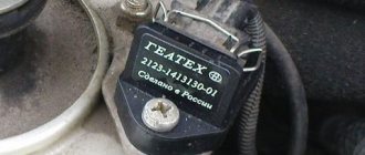
DTOZH 8 – coolant temperature sensor, on the thermostat.
DUTOZH 9 – coolant temperature indicator sensor. In the block, under the thermostat.
Errors that are displayed on the instrument panel are related to the instrument panel and the sensors that are connected to it.
There is also such a problem when I start it cold, on. radiator cooling fan. Maybe look somewhere else? Please tell me.
If the cooling fan turns on regardless of the engine temperature, it means the sensor is broken (either the sensor itself or the wiring, most often there is a problem with the connector). The same thing as if you remove the connector from the sensor, emergency operation is activated.
It's not brown, according to the diagram it's orange and green, they go to the control unit connector.
Yes, below, to the left of the glove compartment, behind the panel, there is a metal box with a large connector.
The green wire rang from this connector, so it rang in several places on this connector.
After checking the wires, I reset the error by holding the button, drove 200 km and the check still did not light up. Thank you for your advice and help.
How to check on the on-board computer
To carry out a check on the on-board computer, you need to insert the ignition key and simultaneously hold down the button that resets the daily mileage. When the correct actions are performed, all elements on the LCD will light up. And the arrows (speedometer, tachometer, etc.) will begin to quickly and continuously move from zero to the maximum indicator and back. Already here you can see how good the LCD indicator and sensors are.
Next, you can use one of the buttons that switches the functions of the bookmaker. As a result, a set of numbers will appear on the display indicating the version of the program currently installed. Now you need to apply pressure on the key again, then the error codes that are available in this car will appear there.
If you need to reset information from the LCD, it is best to press the button for three seconds, which resets information about mileage during the day. Now it's time to return the light to the sensors and use one of the BC keys. Due to the lack of impact on the system, after about half a minute the instrument panel will return to working condition.
Development of a sniffer and study of the CAN bus protocol
After I have access to listen to the CAN bus, I need to decipher who is transmitting what to whom. The CAN packet format is shown in the figure.
All utilities from the can-utils set can parse CAN packets themselves and provide only useful information, namely:
The data is transmitted unencrypted, which made it easier to learn the protocol. On the Raspberry Pi I wrote a small server that redirects data from candump to TCP/IP in order to parse the data stream on the computer and display it beautifully. For macOS I wrote a simple application that adds a cell to the table for each device address and in this cell I can already see what data is changing.
I press the power window button, I found a cell in which the data changes, then I determined which commands correspond to pressing down, pressing up, holding up, holding down.
You can check that the command works by sending from the terminal, for example, the command to raise the left glass up:
cansend can0 181#0200 Commands that transmit devices via the CAN bus in VAG cars (Skoda Octavia 2011), obtained by reverse engineering: // Front Left Glass Up 181#0200 // Front Left Glass Down 181#0800 // Front Right Glass Up 181#2000 // Front Right Glass Down 181#8000 // Back Left Glass Up 181#0002 // Back Left Glass Down 181#0008 // Back Right Glass Up 181#0020 // Back Right Glass Down 181#0080 // Central Lock Open 291#09AA020000 // Central Lock Close 291#0955040000 // Update Light status of central lock (When you send a command to open/close the lock, the LED on the lock control button does not change state so that it shows the real status of the central lock, you need to send an update command) 291#0900000000 I was too lazy to study all the other devices, so in this list, only what was interesting to me.
Troubleshooting
There are several methods for troubleshooting the problem, but together they constitute a complete diagnosis of the car for faults in the coolant temperature sensor. After all, error number 4 gives a signal about exactly this. You can fix it like this:
- First we check the sensor to see how well it functions. It copes with the assigned tasks, there are no complaints about the speed and clarity of data transmission - let's move on to the next point. Does not respond to signals - most likely, it is completely broken and requires replacement.
- This is followed by checking for contact and absence of plaque. If a problematic connection is identified, the sensor will have to be replaced with a new one. And if the surface is covered with plaque, it is necessary to thoroughly clean the seat.
- Now you can move on to the on-board circuit, make sure that there is contact there.
- The remaining dilemmas usually lie in electronics, for this reason the car is taken to a specialist who can adjust the device. Usually in such a situation the ECU is re-flashed, which means that errors are prudently reset.
How to dismantle and install the Priora dashboard
To dismantle the module, you will need to prepare two screwdrivers – a Phillips and a flathead one. A complete replacement of the Priora tidy looks like this.
- Disconnect the wires from the battery.
- Pull the steering column all the way down and remove the steering wheel from the pin.
- You will also need to remove the cover covering the fuse box.
- Unscrew the 4 bolts holding the instrument panel and remove it.
- Loosen the two mounting bolts of the trim panel and remove it.
- Disconnect the wiring harnesses from the contact groups and completely remove the board from the machine.
Installation is performed in reverse order.
Specialization : Graduated from the State Automobile University, worked for 20 years at GAZ-56, now I drive a Zhiguli.
Source
Decoding errors
Each error code consists of five characters. The last two characters indicate the serial number of the specific error.
The first character changes based on the fault system in the car:
- P – malfunctions in the operation of the power plant or defects in the operation of the gearbox.
- U – disruption of interaction between system units.
- B – electric lifts, airbag and other defects in body systems.
- C – faults associated with the EUR.
- 3 – reserve;
- 1 and 2 – manufacturer codes;
- 0 – general code for on-board diagnostics.
The third character indicates the nature of the malfunction:
- 1 and 2 – inform about the appearance of defects in the operation of the fuel system or malfunctions during the air supply;
- 3 – breakdown in the ignition system;
- 4 – additional control;
- 5 – incorrectly operating components in idle mode;
- 6 – electronic unit, as well as its circuits;
- 7, 8 – gearbox malfunction.
What is the CAN bus for in a car?
The spread of the CAN interface in the automotive sector is due to the fact that it performs a number of important functions:
- simplifies the algorithm for connecting and operating additional systems and devices;
- reduces the influence of external interference on the operation of electronics;
- provides simultaneous receipt, analysis and transmission of information to devices;
- accelerates the transmission of signals to mechanisms, running gear and other devices;
- reduces the number of required wires;
In a modern car, the digital bus ensures the operation of the following components and systems:
- central mounting block and ignition switch;
- anti-lock braking system;
- engine and gearbox;
- airbags;
- steering gear;
- steering wheel sensor;
- power unit;
- electronic units for parking and door locking;
- tire pressure sensor;
- windshield wiper control unit;
- high pressure fuel pump;
- sound system;
- information and navigation modules.
This is not a complete list as it does not include external compatible devices that can also be connected to the bus. Car alarms are often connected this way. A CAN bus is also available for connecting external devices for performance monitoring and diagnostics on a PC. And when you connect a car alarm together with a beacon, you can control individual systems from the outside, for example, from a smartphone.
Error 1602
If the standard on-board computer of the Lada Priora 16 valves showed error 1602, then this indicates that the on-board voltage in the controller has decreased.
As practice has shown, this error 1602 does not affect the performance of Priora in any way.
If you remove the terminal from the battery, the problem disappears for a while, but it will definitely appear again. There may be more than one reason for this error to appear:
- Generator malfunction. To determine accurately, you need to measure its voltage in operating condition, it should be within 14 V.
- A large voltage drop when starting the engine also leads to this error. First of all, you need to check the ground and the ECU.
- This error code also appears when the security system blocks one of the electrical circuits.
Priora, CAN, ABS.
Priora, CAN, ABS.
Post by TUN » 12/12/2014, 08:34
I was faced with a difficult problem. A lot of related questions arose. If you have any information, I would be very grateful.
The panel on the Priora burned out due to the radio. The suppliers made a mistake and brought something that wasn’t quite right. The electrician, after almost finishing everything, came up to me and said that one connector did not match.
There was a panel with a can-bus on the car. They brought it without. As a result: 1 The bosch ME 17.9.7 B574DD02 controller generates an error on the can-bus. But at the same time the tachometer works and the check goes out. 2 ABS does not work and does not communicate.
As far as I understand, I will now need to: 1 change the block to another software, together with Eprom. I'll probably fill it with DD04. — the canbus error will go away. 2 Reinstall the two CAN bus wiring from the front harness that goes to the ABS, because the ABS on this car only works via the CAN bus. Before the ECU and diagnostic block.
But this raises several questions.
1 Will the ECU with new firmware for the K-line start reading ABS via the CAN bus? 2 Let’s say the ECU and ABS start communicating with each other via the CAN bus, will the ECU then be able to extinguish the ABS lights on the unit via the K line? In other words, is this ABS9(can) compatible with this combination? 3 Which software is better to choose? 4 And what kind of connector is this? It has nothing to do with ABS - I checked it on a similar car. It comes from the ECM harness (near the controller) to the rear harness. Two wires in the connector are a channel bus. There is only one wire on the connector in the new panel, I suspect it is the K-line.
P.S. I just really feel sorry for the person who spent two days installing this panel. And so there is a chance to do a good deed and earn money.
Source
Error p0504
Many drivers do not understand what the appearance of code p0504 on the display means. This error appears when the brake pedal sensor is faulty. To determine the exact reason for the appearance of this code, you need to disassemble the sensor and carefully examine it. Perhaps one of the springs has burst or the contacts have simply burned out. In some cases, error p0504 on a Priora appears due to the incorrect position of the brake pedal sensor. It must be installed in the correct position, then error p0504 will disappear.
What is CAN bus
A CAN bus is one of the devices in a car’s electronic automation, which is tasked with combining various sensors and processors into a common synchronized system. It ensures the collection and exchange of data, through which the necessary adjustments are made to the operation of various systems and components of the machine.
The abbreviation CAN stands for Controller Area Network, that is, a network of controllers. Accordingly, a CAN bus is a device that receives information from devices and transmits it between them. This standard was developed and implemented more than 30 years ago by Robert Bosch GmbH. Now it is used in the automotive industry, industrial automation and the design of objects designated as “smart”, such as houses.
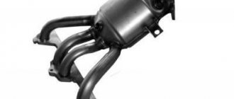
Error p0422
This error informs the owner of the Priora that the effectiveness of the neutralizer has been reduced below the permissible level. Practice shows that error p0422 appears on the screen of a 16-valve Priora quite rarely, but if it does happen, you must:
- Inspect the catcollector. Its body must be free of mechanical damage.
- If any defects are found, it must be replaced.
- If the cause of error p0442 is not in this element, you need to contact specialists, since in some cases the catalytic collector will need to be re-flashed.
Error p1558
It often appears when the throttle valve is not operating correctly, the quality of which leaves much to be desired. It does not interfere with the proper functioning of the engine, but you should still try to remove it. Some people prefer to solve this problem by flashing it, but there is another way.
To do this, you need to remove the throttle valve, disassemble it and lubricate the plastic gear, which is the working part of this element. In most cases, after lubricating the gear, error p1558 disappears.
Self-diagnosis
Once the main code errors have been studied, you can perform self-diagnosis of the car. The Lada Priora has a special controller that allows you to perform diagnostics. If an on-board computer is installed in the car interior, then diagnostics are performed with its help. In addition, there is special equipment that allows you to more accurately perform this procedure.
Diagnostics begins with activation of the test mode. The procedure is performed as follows:
- Turn off the ignition and hold down the mileage reset button, then turn it on again without releasing the button.
- When the ignition is turned on, all components located on the instrument panel will begin to glow. All devices will begin to move to the maximum mark, and then back. This behavior of the car indicates the beginning of the diagnosis.
- Next, we move on to the right steering wheel switch, on which there is a button for switching the settings of the on-board computer. After clicking on it, an information message with the software version will appear on the screen.
- After pressing the button again, error diagnostics will begin. Error codes will appear on the display, which can be deciphered using the corresponding table.
- Once the diagnostics are complete, you can reset the error data. To do this, hold down the mileage reset button for five seconds.
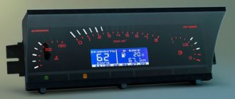
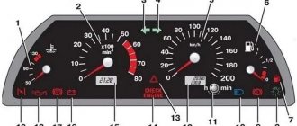
Icons on the Priora dashboard
Please describe the icons on the Lada Priora instrument panel.
- Tachometer . Crankshaft rotation speed. The needle must not go into the red zone. The red zone is dangerous for the engine.
- Brake force distributor malfunction lamp . Lights up red for a few seconds when the ignition is turned on. If the lamp lights up in other cases, this may indicate a system malfunction.
- Battery charge lamp. Lights up red when the ignition is turned on and goes out immediately after the engine starts. If it lights up even after starting the engine, this indicates that the battery charge has expired/the battery is faulty.
- Left turn indicator. Flashes when the turn signal is on, also flashes when the hazard lights are on.
- Speedometer. Shows the speed of the car.
- Emergency oil pressure lamp. Lights up red when the ignition is turned on and goes out immediately after starting the engine. If the lamp is lit in any other case, this indicates low pressure in the system. Operating the car in this case is dangerous for the engine.
- Right turn indicator. Flashes when the right turn signal or hazard warning lights are on.
- Parking brake. Lights up red when the handbrake is applied.
- Coolant temperature indicator. Under normal conditions, the needle is located in the middle of the scale. Engine operating temperature is 90 degrees and above to the red zone. The arrow should not fall into the red zone, which indicates engine overheating. In this case, it is prohibited to further operate the car. You can continue using the car as soon as the needle drops to normal values.
- Fuel level indicator in the gas tank. P shows the fuel level. If there is no gasoline, the fuel pump may fail.
- Fuel reserve lamp. Lights up when there is less than 10 liters of fuel left in the tank. Also, a beep sounds.
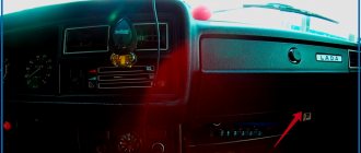
- Button for switching display modes and resetting the daily mileage counter. To reset the daily mileage, hold the button pressed for 3 seconds.
- Alarm. Flashes along with turns when the emergency lights are turned on.
- EUR malfunction icon. Lights up yellow when the ignition is turned on for a few seconds and goes off. In other cases, if the lamp is lit, it indicates a malfunction of the EUR.
- High beam headlight lamp.
- Lamp for turning on external lighting. Lights up when the headlights and low beam are turned on.
- Airbag system malfunction icon. Lights up yellow for a few seconds when the ignition is turned on and goes off. If the lamp burns in any other cases, it may indicate a malfunction in the airbag system.
- Immobilizer icon. Lights up or flashes yellow and displays the status of the immobilizer system and the vehicle's security mode. If the system is in order and the engine is allowed to start, when the ignition is turned on, the lamp flashes 1 time and goes out.
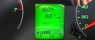
- LCD display of on-board computer. Displays information from the on-board computer, as well as daily and total mileage.
- Unfastened seat belt. Lights up when the ignition is turned on if the driver's seat belt is not fastened.
- Brake system emergency lamp. Lights up red when the ignition is turned on for a few seconds and goes out. The lamp also lights up when the brake fluid level is insufficient and when a malfunction occurs in the service brake system.
- Passenger airbag deactivation icon (optional). Lights up when the ignition is turned on.
- ABS fault icon (optional). To check, the lamp lights up when the ignition is turned on and goes out after a few seconds or after the engine starts. If the lamp is lit, there is a malfunction in the ABS system. However, the performance of the braking system is not affected.
- Engine fault lamp. Check Engine. To check, it lights up when the ignition is turned on and goes out after the engine starts. In other cases, the lamp is lit indicating an engine malfunction. It is not recommended to operate the car in this case.
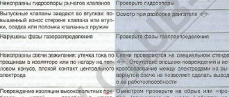
ABS fault detection
You can find out about problems with the ABS by looking at the indicator light on the instrument panel. If it lights up for no reason or does not go out after the required period of time, you need to go to a service station and undergo computer diagnostics. Modern Priora ECUs have a diagnostic connector through which you can easily connect a portable scanner or a stationary motor tester.
All ABS electronics are connected to the mechanical part of the car, so only an experienced diagnostic technician can accurately determine the error that the system produces. ABS error codes start with 0035 and end with 0800. In order to deal with them correctly and determine the reason for the light bulb to light up, you need to have a table of error decoding on hand or resort to qualified help.
Required
The Itelma instrument panel with navigation can be of two types (externally they are no different):
They are not interchangeable, so before purchasing, you should determine whether your vehicle uses a CAN bus or not.
- until 06.2012, cars were produced without a CAN bus;
- remove the instrument cluster and look at the article number or at the block with wires (see pinout of connectors below).
For Kalina (VAZ 1117, 1118, 1119) - all cars without a CAN bus.
- Right steering column switch with joystick (catalog number: 1118-3709340-20);
- Antenna (for roof installation): 1118-7903074.
You can also buy ready-made kits (device + antenna + switch):