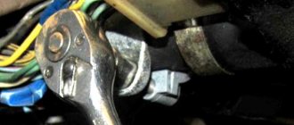
To start the car and set it in motion, the first thing we must do is place the key in the ignition, thereby starting the engine. Also, with the help of this device we can shut down the engine and control the electronics modes.
The ignition switch is the starting mechanism of electrical equipment that supplies voltage to the electrical circuit. The starter spins the engine using the flywheel, a large disc with teeth located between the clutch and the engine. During starting, the teeth of the starter and flywheel are brought into mesh position. At this time, the engine rotates according to a control signal from this lock using battery power.
During operation, the ignition switch supplies current from the battery to the starter traction relay. This is an important part, without which the machine will not fulfill its purpose. In addition to power control, the ignition switch prevents battery discharge in a quiet state. The engine starts from the starter by turning the key.
Types of the castle
Let's take a closer look at what ignition switches are. The following types of locks are found on the VAZ-2109 car:
- New sample. The lock has three positions and a short key.
- Old style. The lock has four positions, a long key and an ignition relay, the fourth position is for the parking light.
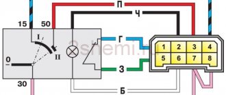
The key is removed in one position with the system turned off. In the first position the radio is turned on. In the second operating position, all electrical consumers are started. At the starting location, one starter is turned on, and the power supply to the system that consumes power is turned off. When the engine is running, the key returns to the second position. When at rest without a key in the lock, in the zero position, only lighting devices and alarms can continue to operate.
Thus, having studied the ignition switch diagram for the VAZ-2109, it should be noted that the lock consists of mechanics and electrics, where contact wires are located that supply current and thus start the car.
1200 rub. for the photo report
We pay for photo reports on car repairs. Earnings from 10,000 rubles/month.
Write:
The ignition switch, or ignition switch , is the main switching component that controls the flow of power to electrical systems and also prevents the battery from draining when the vehicle is parked and at rest.
What is
First, let's look at the structure of the castle. Let's find out what it looks like, what it consists of, what its operating principle is, and so on:
- As mentioned, the ignition switch is a very important element of the VAZ 2109 car, because almost all available equipment is connected to it.
Note. Although there are components that do not depend on the lock in any way. Here they are: license plate lights, brake lights, parking lights, hazard lights, interior lights and lights on the dashboard.
- There are different types of ignition switches: new or old type. The first version without a relay has three positions and a short key, the second with a relay has four positions and a long key.
VAZ 2109 ignition switch malfunction
Scheme
Below is a typical diagram of the ignition switch on the “nine”.
| In key position “0” | The VAZ 2109 is de-energized, and there is power only in the wires that go directly to the battery |
| In key position “1” | The following car components are working: external lighting, headlights, instrument lighting, interior light, all control devices, wipers, heated windows, etc. |
| In position “2” | The starter turns on and all position “1” circuits work |
| In position “3” | All circuits including brake light |
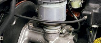
The ignition switch consists of two parts:
- Mechanical - cylindrical lock (cylinder), it consists of a cylinder, into which the ignition key is inserted.
- Electrical - contact unit, consists of a group of contacts that closes using a certain algorithm when the key is turned.
The ignition key usually has a cylindrical lock, which copes with several tasks simultaneously, such as turning the contact assembly and locking the steering wheel. To lock, it uses a special locking rod, which, when you turn the key, moves out of the lock body and into a special groove in the steering column. The ignition switch itself has a simple design; now let’s try to disassemble all its components. For a more clear example, let’s look at how the ignition switch works:
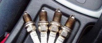
Ignition switch parts
- a) type KZ813;
- b) type 2108-3704005-40;
- Brace.
- Frame.
- Contact part.
- Facing.
- Lock.
- A - hole for the fixing pin.
- B—fixing pin.
The cylinder is connected to a wire and installed inside a wide cylindrical spring, with one edge attached to the cylinder itself, and the other directly to the lock body. Using the spring, the lock can automatically return to its original position after turning on the ignition or after an unsuccessful attempt to start the power unit.
The lock driver can not only rotate the contact unit disk, but also fix the lock in the desired position. Especially for this purpose, the leash is made in the form of a wide cylinder, in which there is a radial channel passing through. There are balls on both sides of the channel, between them there is a spring, with the help of which the balls enter the holes from the inside of the lock body, thus ensuring their fixation.
The contact assembly has two main parts , such as: a contact disk that can be driven and a stationary block with visible contacts. There are plates installed on the disk itself; it is through them that current passes after turning the key in the ignition switch. Basically, up to 6 or more contacts are placed on the block; their outputs, as a rule, are located on the reverse side. Today, modern locks use contacts in the form of plates with a single connector.
Operating principle of the ignition switch
The lock's operating system is quite simple, so now let's look at the main tasks it can handle:
- The ability to connect and disconnect the vehicle’s electrical power system to the battery, in turn, after starting the engine, connect to the generator.
- Ability to connect and disconnect the engine ignition system to the power source.
- When the engine is started, the ignition switch may turn on the starter for a short period of time.
- Ensures the operation of such devices when the engine is off , such as: radio and alarm.
- Some ignition switch features can be used as an anti-theft feature , such as the ability to lock the steering wheel when the engine is at rest.
Ignition switches can have from two to four switch positions. Depending on the position of the ignition key in the car, you can determine which power systems are working at one time or another. The key in the car can only be pulled out in one position, when all power consumers are turned off. To have a more detailed understanding of the operation of the ignition switch, you need to familiarize yourself with its diagram:
Ignition switch operation diagram
In what positions can the ignition switch operate?
- "Turned off" . In cars of domestic manufacturers, this position is displayed as “0”, but on some older models the position had the value “I”. Today, in improved cars, this mark is not displayed on the lock at all.
- “On” or “Ignition” - on domestic cars the following designations are found: “I” and “II”, in newer versions it is “ON” or “3”.
- “Starter” - domestic cars “II” or “III”, in new cars – “START” or “4”.
- “Lock” or “Parking” - old cars are designated “III” or “IV”, foreign cars are marked “LOCK” or “0”.
- “Additional equipment” - domestic locks do not have this provision, foreign versions of the car are designated: “Ac” or “2”.
Ignition switch position diagram
When the key is inserted into the lock and turned clockwise, that is, it moves from the “Lock” to the “ON” position, then all the main electrical circuits of the car are turned on, such as: lighting, windshield wiper, heater and others. Foreign cars are designed a little differently; they have “Ass” immediately before the “ON” position, thus additionally starting the radio, cigarette lighter and interior lights. If you turn the key further clockwise, the lock will move to the “Starter” position, at this moment the relay should connect and the engine will start. This position cannot be locked because the key itself is held by the driver. After successfully starting the engine, the key returns to the initial position “Ignition” - “ON” and already in this state the key is fixed in one position until the engine stops completely. If it is necessary to turn off the engine, then in this case the key is simply turned to the “Off” position, then all power circuits are turned off and the engine stops.
Diagram of the key operation in the ignition switch
In cars with diesel engines, a valve is turned on to shut off the fuel supply and a flap that closes the air supply; as a result of all these actions, the electronic unit that controls the engine stops its operation. When the engine is completely stopped, the key can be switched to the “LOCK” position, after which the steering wheel becomes motionless. In foreign cars, in the “LOCK” position, all electrical circuits are turned off and the steering wheel is locked; cars with an automatic transmission additionally block the selector, which is in the “P” position.
VAZ 2101 ignition switch wiring diagram
Power-up modes used
At each of the turns, the connection of certain devices is provided. There are markings in a circle in front of the socket indicating the position to which a certain mode corresponds.
Null
To activate this mode, just insert the key into the “secret”. In this case, devices that are directly connected to the battery remain active.
Additional consumers will be put into operation after the larva is rotated at a certain angle. Voltage is supplied to pins 30/1 and 30.
The first is “ignition”
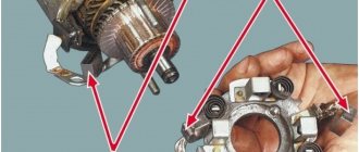
In the first position, the driver can turn on the front lighting, such as the low and high headlights. The tidy and interior light up responsively. The connection diagram for the VAZ-2109 ignition switch is activated during this turn, releasing current to the 30–INT pair.
When there is a connection between terminals 30/1 and 15/1, the rear lights, reversing lights, turn signals are operational, and the generator excitation winding is energized. The XX solenoid valve also receives power.
In this position, contacts 30/1 and 15/2 are closed, which ensures the operation of, in addition to the head light optics, the functioning of the fog lights, the rear window wiper and its heating. The headlight cleaners, heater fan and engine cooling system propeller are connected to this contact.
The second is the “starter”
By moving the key to the current position, the driver does not block the connection of electrical consumers that were started in the previous “ignition” position. This fully applies to both the closed contacts of the pair 30/1 - 15/1, and to the pair 30 - INT.
The main change that the VAZ-2109 ignition switch connection diagram provides in such a situation is the activation of a pair of contacts 30–50. This allows the starter to start.
It is important to know that the key is not held in the “starter” position on its own, but springs back to the previous position automatically as soon as the driver releases the force.
Third – “parking”
At this angle of rotation, consumers started in the “ignition” position and closed contacts 30 – INT remain activated. A closed pair 30/1 - P is also added. It is responsible for the parking lighting.
How to properly connect the ignition switch
If the wires are collected into one chip, then connecting the lock will not be difficult, you just need to install it on the contacts.
If the wires are connected separately, then you need to pay attention to the diagram:
- terminal 50 – red wire, the starter operates with it;
- terminal 15 – blue with a black stripe, responsible for heating the interior, ignition and other devices;
- terminal 30 – pink wire;
- terminal 30/1 – brown wire;
- INT – black wire responsible for dimensions and headlights.
Wiring diagram
If the wiring has been connected, then everything needs to be assembled and the terminal connected to the battery and checked for functionality. First, you need to check whether all electrical appliances have power from the lock, then check the operation of the starter itself. If any malfunctions are detected , you need to once again check that the wires are connected correctly , because the operation of all devices in the car after turning the key will depend on this. Next, you can familiarize yourself with the ignition switch wiring diagram.
Testing the serviceability
The lock's service life is limited. After it fails, it is necessary to repair or completely replace the product. The functionality is checked after inserting the key into the “secret”.
Failures occur due to mechanical wear or loss of contact. The check is carried out by turning the key. If it begins to jam, then as a temporary solution it is possible to use silicone grease by dripping it inside.
In order for the wiring diagram to function correctly, you need to know which contacts to connect to each other. Typically the following wiring system is used:
- red connects to the cable from the starter;
- the pink wire goes to “+” from the 12 V battery;
- brown +12 V is used to start the ignition relay;
- white – relay on;
- black and blue connect other consumers.
It is necessary to check the contacts for the presence of carbon deposits or the possibility of oxidation. Burning contacts can be heard in the cabin by the characteristic smell of burnt insulation.
Voltage is supplied to the electrical power circuits of consumers of the electrical equipment of the VAZ 21093 car through the ignition switch (lock).
Let's consider the order of connecting the wires to the ignition switch, the pinout of the ignition switch terminals and the purpose of each wire (to which circuit it supplies voltage).
For current unloading of the ignition switch contacts, an ignition relay 113.4737-10 is included in its circuit, which is mounted next to it under the instrument panel.
Wires of the ignition switch of a VAZ 21093 car - connection order, pinout of contacts
Ignition key position: “O” (off)
The lock contacts “30” (pink wire – “plus” from the generator) and “30/1” (brown wire – “plus” from the generator) are energized. No electric current flows into the system.
Key position: “I” (ignition)
Contacts “30” (pink wire) and INT (black wire) are closed. Voltage is supplied through one black wire to the exterior lighting switch, instrument lighting switch, through the other to the steering column switch for briefly turning on the high beam headlights.
Contacts “30/1” (brown “positive” wire) and 15/1 (white wire) are closed. Voltage is supplied to the generator excitation winding, the ignition system, to the windshield wiper, carburetor solenoid valve control unit, turn indicators, reversing lamps, and control devices.
Contacts “30” (pink “positive” wire) and “15/2” (blue wire) are closed. The low and high beam headlights, fog lights, headlight cleaners, rear window cleaner, heated rear window, washer, heater fan, and engine cooling fan on the radiator are turned on.
Key position “II” (starter)
Contacts “30” (pink wire) and “50” (red wire to the starter) are closed.
In addition, “30” and “INT” remain closed, as well as 30/1 (brown wire) and “15/1” (white wire on the ignition relay).
Key position “III” (parking)
“30” and “INT”, “30/1” and “P” are closed (on VAZ 2108, 2109, 21099 cars this contact was used to turn on the parking light, the wire is yellow).
Notes and additions
The following are not powered through the ignition switch: emergency, sound, light alarms, interior lighting, dimensions, brake lights. security alarm. electric door locks (if equipped).
For the VAZ 2109, as well as for all other cars, the ignition switch is one of the most basic elements of electrical equipment. This element consists of a mechanical and electrical part. The mechanical part is responsible for locking the steering wheel when there is no key in the lock, and the electrical part is responsible for supplying voltage to the necessary electrical circuits depending on the selected position.
How does a contact group work?
The contact group in the car is designed to connect all the electrical circuits of the car and group them. When the driver turns the ignition key, the electrical circuit is closed from the minus terminal, which is located on the battery, to the ignition induction coil. Electric current from the wire system goes to the ignition switch, passes through the contacts on it, after which it is sent to the induction coil and returns to the “plus” terminal. The coil provides high voltage to the spark plug, through which current is supplied, then the key closes the contacts of the ignition circuit, after which the engine starts. After the contacts have closed with each other using the contact group, the key in the lock must be turned to several positions. After this, in position A, when the circuit from the power source distributes the voltage, all electrical appliances will start.
Exactly three switched contacts
One line through which current is supplied, and only one ignition circuit - this solution is typical for all VAZ cars, if we talk about the “2110”, “2170” and later families. Even in Grants, produced since 2012, the additional ignition circuit did not appear. In general, with the transition to the “Ten” family, three “significant” terminals of the lock remained:
- Contact "30";
- Terminal “15” (can be designated as “15/1”);
- Terminal "50".
The ignition switch circuit looks trivial, even if we talk about the Lada 2110.
Ten and its ignition switch, diagram Diagram and connector of the ignition switch of modern models Ignition switch connector Tens
The Tens connector has 8 terminals. And in Priora, as well as in Grant and Kalina, this number is reduced to three (Fig. 2).
Of the 8 terminals available in the VAZ-2110 connector, the 7th and 8th simply duplicate each other. Two more are connected to the button, and another pair of terminals are connected to the lamp.
The lock connector of all VAZ models, starting from “2170”, is equipped with only three contact terminals. And the additional connector, which is equipped with a pair of terminals, is connected to the immobilizer in these cars.
The “3” mark has disappeared from the “Tens” lock cylinder. And until now, VAZ produces just such locks, where the key can be installed in one of the following positions:
The presence of the “Parking” mode, as you can see, is not provided here.
What can happen to the ignition switch
Most often, the ignition switch itself, the contact group or the locking mechanism can break down . Each breakdown has its own differences:
- If, when inserting the key into the cylinder, you notice some difficulties when entering , or the core does not turn well enough, then you should conclude that the lock has become faulty .
- If you cannot unlock the steering shaft in the first position, there is a breakdown in the locking mechanism .
- If there are no problems in the lock, but the ignition does not turn on , or, on the contrary, it turns on, but the starter does not work, then the fault must be looked for in the contact group .
- If the cylinder fails , then a complete replacement of the lock ; if the contact unit is broken, then it can be replaced without the cylinder. Although today it is much better and much cheaper to completely replace it than to repair the old ignition switch.
As a result of all the above, I would like to say that the ignition switch is one of the most reliable parts in a car, but it also tends to break. The most common breakdowns that can be encountered are jamming of the cylinder or its general wear, corrosion of the contacts, or mechanical damage to the contact unit. All these parts require careful care and timely diagnostics in order to avoid serious malfunctions. And if you didn’t manage to “outwit fate,” then in order to cope with its repair yourself, you must know the structure of the ignition switch and the principle of its operation.
Repair and replacement
Typically, the lock can be repaired. If this fails, you will have to completely replace it (see Replacing the VAZ ignition switch on your own). Repairing a lock in most cases comes down to replacing the cylinder or contact group. If after this the problem has not been resolved or it is possible to change the entire lock, then it is better to do the latter.
VAZ 21093 ignition switch
Larva and its replacement
So, we do the following:
- Remove the steering column cover and unscrew the fastening bolts that tighten the ignition switch clamp.
Note. The bolts have sheared heads and then you will have to use a hammer and chisel. The bolts are first loosened by blows with a chisel, and then unscrewed with pliers.
- We separate the two parts of the clamp so that they disengage;
- The larva can be changed already at this stage of the operation;
- We take out the side pin that holds the cylinder in the lock.
Advice. The cylinder can be easily removed with a thin screwdriver, for example, from a watch. At the same time, you need to tap the lock with a hammer.
- If you cannot pull out the cylinder after the side pin has been removed, you can try to drill out the cylinder using a thin drill;
- If again it was not possible to remove the cylinder, then it is recommended to finally remove the lock;
- Remove the wire plugs.
Note. One of the plugs (the one with the larger connector) is located under the dashboard. To remove it, you need to put your hand under the panel.
- If the ignition switch has a relay, then take it out from under the panel;
- Disconnect the connector;
- We also remove the ground wire;
- Remove the cover by pressing the latch, and then the contact group;
- Now it will be much easier to remove the larva;
- We replace it with a new one;
- We check the work on site before putting everything back into place. We turn the key inside the lock - all the processes described above should work.
Note. Don't forget to also check that the steering wheel lock works. If the steering shaft does not lock when the steering wheel is turned completely, we adjust the correct location of the lock on the column.
- After a thorough check, making sure that everything works correctly, tighten the bolts until the heads come off. It is advisable to use the key at “10”.
contact Group
Lock contact group
Replacing the contact group of the lock, if this is the fault of the lock, is the most profitable from the point of view of monetary costs. The actions boil down to removing the lock (how to do this is written above). Here are some guidelines to follow:
- Before disconnecting contacts, you need to number them to avoid confusion;
- Some models of locks in the contact group design have a retaining ring, which must first be removed. This is most easily done using an awl.
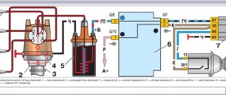
Wiring diagram for the ignition switch on the VAZ-2108, 2109 and 21099
Wiring diagram for the ignition switch on the old-style VAZ-2108, 2109 and 21099 with an unloading relay.
Pinout of the VAZ-2109 ignition switch with unloading relay:
- comes +12V in position I, II, III (parking)
- comes +12V in position I, II, III (parking)
- comes +12V in position III (parking)
- position I, +12V goes out after turning on the ignition (contact 15/2), disappears at start (II);
- position I, +12V goes to the starter (pin 50);
- position I, +12V goes away after turning on the ignition (pin 15), does not disappear when starting II;
- +12V comes from the battery (pin 30);
- comes +12V constantly.
Wiring diagram for the ignition switch on the VAZ-2108, 2109 and 21099 of the new model, without a relay.
Pinout of the new VAZ-2109 ignition switch:
- comes +12V constantly
- comes +12V constantly
- +12V arrives after turning on the ignition (pin 15), does not disappear when starting II;
- +12V arrives after turning on the ignition (contact 15/2), disappears at start (II);
- position I, +12V goes to the starter (pin 50);
- +12V arrives after turning on the ignition (pin 15), does not disappear when starting II;
- +12V comes from the battery (pin 30);
- comes +12V constantly.
Photo 1, pinout of the new VAZ 2109 ignition switch
Photo 2, pinout of the new VAZ 2109 ignition switch
“Classics”, as well as the “Ninth” family
Fiat engineers, when developing the ignition switch for their 124 model, used two supply lines (“30” and “30/1”). The ignition line was the only one.
Connecting the VAZ-2101 lock terminals 5 terminals on the lock module Connecting the VAZ-2109 ignition switch (color coding)
Another ignition circuit containing contact “15/2” was added during the transition to the “2109” family. It, in turn, is switched using a relay. In different families, only the diagram differs, but not the “behavior” of the car when the key is installed opposite the marks:
- Position 0: everything is off;
- Label 1: ignition and engine operation;
- Mark 2: starting the starter;
- Label 3: “Parking” mode.
To turn off the engine, turn the key to position “0”. The spark plugs lose spark and the engine stops.
The ignition switch module, if we talk about the “classic family”, is equipped with 5 terminals (see Fig. 2). Starting from the “2109” family, this solution is not used. Several wires come out of the lock cylinder and are connected to a remote connector.
The connector layout can be easily identified using the color coding (see diagram above). When carrying out any installation work, remember the following: you must turn off the engine, open the hood and disconnect one of the battery terminals. Usually the negative one is turned off.
Ignition switch VAZ 2109 faults
The ignition switch of the VAZ 2109 is a very important and at the same time very capricious mechanism of the car. And in today’s article we will try to analyze its importance and capriciousness, i.e. its malfunctions. The ignition switch serves to supply voltage to electrical circuits depending on the location of the key. The castle consists of 2 parts. These are the mechanical and electrical parts.
As has already been written, in our nine the ignition switch is a very important mechanism. Almost all of the car's electrics pass through it. Without an ignition switch, only a few devices can operate and these are:
1. Side lights.
2. Emergency alarm.
3. Interior lighting.
5. Rear number plate illumination.
This is necessary so that when stopping on the highway or in the city in an unlit place, we do not need to turn on the ignition in order to be noticed.
Pinout of mounting block 2110
| K1 | Relay for monitoring the health of lamps (contact jumpers are shown inside, which are installed instead of the relay) |
| K2 | Windshield wiper relay |
| K3 | Relay-breaker for direction indicators and hazard warning lights |
| K4 | Low beam relay |
| K5 | High beam relay |
| K6 | Additional relay |
| K7 | Heated rear window relay |
| K8 | Rear Fog Light Relay (Backup Relay) |
VAZ instrument cluster diagram
2110,2110, 2111, 2112
Expert opinion
It-Technology, Electrical power and electronics specialist
Ask questions to the “Specialist for modernization of energy generation systems”
Fuse block 2114-3722010-60 There is no brake pad wear sensor. Previously, the handbrake lamp flashed when the lever was raised, and came on constantly when the sensors on the brake pads were activated. Ask, I'm in touch!
The ignition switch of the VAZ 2109 is faulty.
The most common problem with the ignition lock is its working out and jamming. If these symptoms occur, you should immediately replace the entire ignition switch, because in case of jamming, you can simply burn the starter and then the repair will cost you the cost of the starter. Another common problem is the failure of the contact group. In this case, several devices fail at once. For example, my low beam headlights, heater, cigarette lighter, and rear window heater immediately stopped working. Replacing the contact group with a new one, everything worked immediately.
© 2022 Repair and tuning of domestic cars Joomla! is Free Software released under the GNU General Public License.
Name of modes, position of the lock and power circuit.
| Key position in the lock | Live pin numbers | Circuits that are included |
| 0 - disabled | 30 and 30/1 | The car is de-energized, power is provided only in circuits connected directly to the battery |
| "I" - ignition | 30 - INT | At the current position of the key, the external lighting, high and low beam headlights, instrument lighting and lighting in the car interior work. |
| 30/1 — 15/1 | All control devices, reversing light, windshield wiper, generator excitation winding, direction indicators, idle speed solenoid valve control unit must work. | |
| 30/1 — 15/2 | In this position, the low and high beam headlights, rear front fog lights, rear window cleaner and heating, washer, heater fan, engine cooling system fan, and headlight cleaners operate. | |
| "II" - starter | 30 - INT | The same circuits operate as in the ignition position. |
| 30/1 — 15/1 | The same circuits operate as in the ignition position. | |
| 30 — 50 | The starter turns on | |
| "III" - parking | 30 - INT | The same circuits operate as in the ignition position. |
| 30/1 - R | Parking lighting |
Design and troubleshooting of the ignition switch of the VAZ 2109
One of the key components on a VAZ 2109 vehicle is the ignition switch. The electrical circuit of the machine uses it as a switching unit, providing voltage to the necessary power circuits. If this does not happen due to a malfunction of the switch, then it is possible to turn off individual groups of consumers or the car as a whole - it simply will not start.
Typical faults
VAZ 2109 ignition switch
The lock belongs to the car's ignition system. Let us note right away that if problems are observed, you can fix them yourself, because, as a rule, the “nine” is equipped with an outdated ignition system that does not require diagnostics and repair at a service station.
How to make sure there is a problem
Below is a tip on how to make sure that the ignition switch is really not working:
- We insert the ignition key and turn it to a certain position. A short circuit in the circuit must necessarily occur. We look at the diagram: if the key is in position “1”, is the external lighting or control devices working;
- It is recommended to check at all positions of the lock. If deviations from the norm are observed, there is a problem with the lock;
- You can also check the functionality of the ignition switch in the following way: turn the steering wheel, which should not be blocked. The lock on a working steering wheel should only work when the key is turned a second time from position “1” to position “2”;
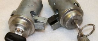
Design and principle of operation of the lock assembly
On a VAZ 2109 car, 2 standard modifications of the lock can be installed. The old one has catalog number 21080-3704005-60. It features four key positions (long), and also contains an ignition relay. The new unit with catalog number 21080-3704005-30 has only three key positions and does not have a relay.
To connect all the wires to the VAZ 2109 car lock, a contact group is used. Each of the key positions has its own blocking, and therefore consumer groups.
Contacts “30” and “30/1” are closed. All dependent power circuits are disabled.
In this position, voltage is supplied to the elements of the ignition control system. To do this, the white and brown wires are connected, and the pink wire is connected to black and blue. In this case, several groups of contacts are formed. For example, “30 INT” turns on the power supply circuit for external lighting, including high beam lighting, and the dashboard lighting. Contacts “30/1” and “15/1” provide voltage to the direction indicator lamps, reverse lights, elements of the ignition system, etc. The pair “30/1”, “15/2” powers the low/high beam headlights, fog lights , washer, fans.
The ignition relay, which was switched on in the previous step, continues to operate. The main one is a pair of contacts “30”, “50”, which provides voltage for the starter to operate. In parallel to it, circuits should be formed from contact connections “30/1”, “15/1”, as well as “30/1”, “15/2”. The consumers that are connected in this case are similar to those described for position “I”. The pink wire in the contact pair, together with the black one, is shorted to red (instead of blue).
Used to supply voltage to the components of the parking (“30/1 P”) and side lighting/dashboard lighting (“30 INT”) components. The black wire forms a closed circuit with the brown and pink wires.
The lock and its circuit perform two functions: electrical and mechanical. The essence of the first is to close certain groups of contacts based on the position of the key. From a mechanical point of view, when the ignition is turned off, the steering wheel is blocked, making it impossible to rotate. That is, the second function is protective.
A little theory
The ignition switch must switch, that is, connect contacts that supply power to different electrical circuits. The voltage from the battery is supplied to the “30th” contact of the lock, and sometimes two lines are used: “30/1” and “30/2”. Each line is equipped with a 30 Ampere fuse, hence the well-established name.
30 amp fuse painted green
When turning the key, the "30 pins" are usually connected to the following:
- In the “Parking” position – to the “INT” contact, from which current is supplied to additional equipment;
- “Ignition” – to the “INT” contact, also to contacts “15/1” and “15/2”;
- “Start” – to contact “15/1”, but not to “15/2”, as well as to contact “50”.
From terminal “50” power goes to the starter solenoid relay. The “15th” contact, in turn, feeds the main ignition circuit. And if there is an additional circuit, it will be open when the starter operates.
Let us note once again: when the key is set to the “Start” position, contact “15/2” does not receive a positive potential. This is true for all cars of any model, including the VAZ Nine.