Hello everyone, the engine suddenly started to stall, especially when it was cold. Even after warming up, when the throttle was opened sharply, the engine shook noticeably. First of all, we change the spark plugs.
I had Denso TwinTip, but during the test you can change it to the good old AU17DVRM.
Denso were in good condition. Only one candle had a mark as if from a breakdown.
After replacing the spark plugs, the car started working and drove for two days, but then the problem returned.
The next thing is to change the armored wires. Having studied the question, I wanted to purchase Tesla high-voltage wires, but I couldn’t find them on sale and the choice fell on the factory PES/SKK wires. I was pleased with these wires with their workmanship and price; the previous ones ran with me for more than 5 years without any problems.
Hello everyone! I once went in wet weather for a drive in a newly repaired Sena and didn’t recognize the car - it was stuck, the revs were floating, it adjusted at idle, it jerked while driving... I opened the hood and saw that over 8 years of service the high-voltage wires had become unusable, the charge was constantly draining from output of the 4 cylinder ignition coil to a nearby mounting bolt. Plus, the insulation on all the wires was damaged in the place where it fits into the clamps of the engine trim... The solution is clear - replacement with new ones. I climbed onto Existence and was literally blown away - a set of high-voltage wires costs from 3,000 rubles, with a two-week wait... A toad crawled out of the corner and began to whisper that original spare parts are of course good, but there is a crisis in the country, and in general there is little money after the holidays... Moreover, that the wires are made in Russia and it’s generally unclear why the hell this price is... I came to the store and bought wires for a VAZ 2110 injector 8 valves. I bought wires from the company HORS - all silicone, reinforced, blue for 380 rubles. I climbed under the hood, began to try it on, and it turned out that these wires are completely similar to the standard wires for the Sens, except for two small nuances: 1- The wire of the second cylinder is slightly shorter in length and because of this it cannot be completely removed into the standard channel of the engine trim. 2- The diameter of the internal connecting part of the protective moisture-proof cap on the ignition coil side is twice as large as required. Because of this, it is possible for water and other nasty things to get into the contact of the coil, which is accompanied by its failure. I thought and thought and decided that the tenfold difference in cost would pay for the existing shortcomings - which turned out to be very easy to eliminate.
General tips for connecting high-voltage wires.
Checking high-voltage wires. To check the wires, you will need a multimeter tester. Check the resistance of the wires - it should be no more than 20 KOhms (in practice, the longest wire of cylinder 1 has a resistance of up to 10 KOhms). If the wire resistance is more than 20 Kom, it must be replaced. Carefully inspect the wires for chafing on parts of the motor or other wires. In case of significant abrasion, replace the wire. In case of minor abrasion, it is possible to lay the wire so that it does not rub and fix it in this position.
Laying wires. Do not try to connect the wires in a bundle. Disassemble the wiring harnesses, release the wires from the plastic holders. Connect the high-voltage leads to the corresponding cylinder spark plugs. Lay the wires so that they do not rub against each other, engine parts, or hoses. Avoid sharp bends and tension on the wires. After connecting all the wires, secure them into the bundle with special comb holders included in the delivery kit.
The procedure for connecting I/O wires to a VAZ carburetor (2108, 2109, 21099)
The central wire from the distributor cover always goes to the ignition coil (bobbin).
The outlet of the distributor cover, which faces towards the front of the car, is connected to the first cylinder.
The outlet of the distributor cap, looking down, is connected to the third cylinder.
The outlet of the distributor cap, looking rearward, is connected to the fourth cylinder.
The outlet of the distributor cap, looking up, is connected to the second cylinder.
The procedure for connecting high-voltage wires to a VAZ Classic, Niva with a carburetor and distributor.
Central wire from the ignition coil (bobbin)
1 cylinder - above the vacuum corrector. Next, clockwise, the order is 1-3-4-2.
Injection VAZ produced before 2004 with an old-style ignition module (4-pin low-voltage connector)
Actually, on the module body it is already indicated which cylinder the pins correspond to - but we duplicated them in red in case the module gets completely dirty, and you might not be able to see it in the photo.
Injection VAZ produced after 2004 with a new ignition coil (3-pin low-voltage connector)
As with the old-style ignition modules, the new coils are also marked with pins corresponding to the cylinders. But the connection order is different from the order on the old-style ignition module. Be careful.
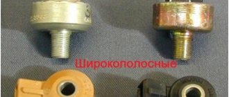
Resistance members
It starts poorly, jerks, does not pull... Very often, such engine ailments are treated by simply replacing high-voltage wires. The nature of the phenomenon is clear - we have written about it more than once. As is known, the spark energy depends on many parameters, including the power of the high-voltage pulse that reaches the electrodes of the spark plug. In other words, from losses in the ignition line. In a carburetor engine, the “science”, in general, ends there, but in an injection engine the influence of the control system is added. Indeed, if the combustion intensity is insufficient or if flares are missed, the feedback will work through the control system, increasing the fuel supply - to compensate for the supposedly excess oxygen. This will affect both gasoline consumption and especially the toxicity of exhaust gases. And if so, then each high-voltage wire actually becomes part of the engine control system!
Hence the purpose of our examination: analysis of the influence of various high-voltage wires on the main indicators of a real VAZ-2112 engine. As usual, everything was purchased from large metropolitan auto stores. We took two sets of wires from ten different companies - domestic and foreign. They took two for a reason - in order to prevent possible accusations of bias. Like, you can’t judge by one example! Let's not argue - it's better to change the verification procedure.
A laboratory ohmmeter was used to determine the resistance of each wire - all 80 of them. Then they measured the length of the wires, divided one by the other and got the linear resistance - in kilo-ohms per meter. Logically, for the same sets there should not be a large spread - the cable is cut from the same reel. But…
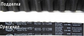
This happened in all sets from eight companies. But at Caesar in two wires it jumped almost an order of magnitude compared to the other six. Master Sport repeated the same picture, albeit for one wire. Little things? Maybe. But so that they do not distort the overall picture, we selected test kits for these brands so that the wires had approximately equal linear resistance, not without reason assuming that they would be quite standard. To compensate for the trouble, they allowed themselves to mutter that the manufacturer should have taken care of this.
Symptoms of module malfunction
Signs of a faulty ignition module on a VAZ-2110 are always acutely felt:
- hesitant engine starting or failure to start;
- failures during sudden changes in speed;
- high fuel consumption;
- two cylinders do not work, the engine is feverish;
- lack of dynamics;
- a sharp drop in power;
- drop in power and thrust after warming up.
Other faults
These symptoms may not only be caused by the ignition module. To determine the malfunction, it is enough to spend a few minutes diagnosing spark plugs, high-voltage wires and caps. This will eliminate the remaining elements of the ignition system and make sure that it is the ignition module that is faulty.
- Checking the spark plugs. To do this, unscrew them, put on the caps, place them on the cylinder head and crank the engine with the starter. The spark should be stable on all spark plugs. We replace non-working spark plugs and repeat the test. Under no circumstances should you crank the engine with the starter with the high-voltage wires removed. This will lead to a breakdown in the ignition module cover.
- Checking the high voltage wires. We remove the caps and hold the wire contact through the insulator at a distance of 10-15 mm from the head. With good wires, the spark should pierce this distance vigorously and confidently. Next we check the wires for resistance. A working wire should have a nominal resistance of 7-10 kOhm. Any deviation from this value indicates the need to replace the entire set of high-voltage wires.
- We check the caps for breakdown.
We also look at the block and especially the wires included in it.
In addition, it is better to check the spark plugs and wires on a warm engine, since a half-dead ignition module can operate cold for some time and fail when heated. You also need to be sure that all sensors are working properly. This can be indicated by an error code or Check Engine light.
Algorithm for checking the ignition module on a VAZ-2110
We begin the test with the block connected to the module.
To check the module, we only need a multimeter and it will take 15-20 minutes. This is quite simple to do, the main thing is to adhere to the algorithm and know the nominal values of the working module:
- We check the power supply and the presence of pulses supplied from the ECU. We check the power between the central terminal (15) of the wire block connected to the module and the engine ground. When the ignition is on, the voltage should not be less than 12 V. Otherwise, either the battery is dead or the ECU does not work.
- We check the pulses from the ECU on the wiring block. We install one tester probe on connector 15, the second on the far right, then on the far left. The assistant cranks the engine with the starter, and at this time we record short-term voltage surges with a tester. If there are no impulses from the ECU, it is he who is to blame.
- We check the resistance on the secondary windings of the coils. We put the tester in resistance measurement mode and measure it at the high-voltage terminals of the module cover. Between pins 1 and 4 and pins 2-3, the resistance should be 5.4 kOhm. Otherwise, the module must be replaced.
- We check the resistance of the primary windings between contacts 15 and the rightmost, then the leftmost terminals. Nominal - 0.5 Ohm. Deviation is not allowed.
- Check the module for a short circuit. In ohmmeter mode, install one multimeter probe on the central terminal, the second on the metal body. There shouldn't be any resistance. If the device detects at least some resistance (other than unity or infinity), the module must be replaced.
General tips for connecting high-voltage wires.
Checking high-voltage wires. To check the wires, you will need a multimeter tester. Check the resistance of the wires - it should be no more than 20 KOhms (in practice, the longest wire of cylinder 1 has a resistance of up to 10 KOhms). If the wire resistance is more than 20 Kom, it must be replaced. Carefully inspect the wires for chafing on parts of the motor or other wires. In case of significant abrasion, replace the wire. In case of minor abrasion, it is possible to lay the wire so that it does not rub and fix it in this position.
Laying wires. Do not try to connect the wires in a bundle. Disassemble the wiring harnesses, release the wires from the plastic holders. Connect the high-voltage leads to the corresponding cylinder spark plugs. Lay the wires so that they do not rub against each other, engine parts, or hoses. Avoid sharp bends and tension on the wires. After connecting all the wires, secure them into the bundle with special comb holders included in the delivery kit.
The procedure for connecting I/O wires to a VAZ carburetor (2108, 2109, 21099)
The central wire from the distributor cover always goes to the ignition coil (bobbin).
The outlet of the distributor cover, which faces towards the front of the car, is connected to the first cylinder.
The outlet of the distributor cap, looking down, is connected to the third cylinder.
The outlet of the distributor cap, looking rearward, is connected to the fourth cylinder.
The outlet of the distributor cap, looking up, is connected to the second cylinder.
The procedure for connecting high-voltage wires to a VAZ Classic, Niva with a carburetor and distributor.
Central wire from the ignition coil (bobbin)
1 cylinder - above the vacuum corrector. Next, clockwise, the order is 1-3-4-2.
Injection VAZ produced before 2004 with an old-style ignition module (4-pin low-voltage connector)
Actually, on the module body it is already indicated which cylinder the pins correspond to - but we duplicated them in red in case the module gets completely dirty, and you might not be able to see it in the photo.
Injection VAZ produced after 2004 with a new ignition coil (3-pin low-voltage connector)
As with the old-style ignition modules, the new coils are also marked with pins corresponding to the cylinders. But the connection order is different from the order on the old-style ignition module. Be careful.
Do-it-yourself installation of the VAZ 2112 ignition module
Having picked up the new coil, first install it in its place by tightening the two nuts that secure it. Then place two wires on the sides of the coil and secure them with retaining nuts. When installing two side wires, pay attention to the markings that are marked on the sides of the ignition coil (see photo below). So this marking indicates which terminal of the coil should be connected to this or that wire
The blue wire must be connected to the “B” marking, and the red wire must be connected to the “K” marking!
So this marking indicates which terminal of the coil should be connected to this or that wire. The blue wire must be connected to the “B” marking, and the red wire must be connected to the “K” marking!
Then place the high-voltage wire on the central part of the ignition coil. And then install the negative terminal on the battery.
Connection features
The order of connecting high-voltage wires must be strictly sequential, since each cylinder of the engine corresponds to a specific socket on the ignition module. Considering that there is a numbering of the sockets on the ignition module body, the risk of confusing anything is minimal.
The procedure for connecting high-voltage wires of the VAZ 2114 injection type depends on the year of manufacture of your car. Fourteen cars before 2004 had 4-pin ignition modules installed, and cars after 2004 had 3-pin coils.
The connection diagram for VAZ 2114 high-voltage wires to the ignition module (until 2004) is as follows:
Connection diagram for VAZ-2114 with ignition coils (after 2004):
In the pictures you can see the numbers of the landing slots. Each number must have a corresponding cylinder connected to it (cylinder numbering is counted from left to right).
To correctly install high-voltage wires on the VAZ 2114, follow the following algorithm of actions:
- Turn off the ignition. Open the hood and remove the power terminals from the battery;
- We remove the old GDPs from the mounting sockets on the module and cylinders;
- We remember the location of the high-voltage wires of the VAZ 2114 and connect new GDPs according to the diagram. Before replacing, it would not be amiss to draw this very diagram by hand on paper so as not to confuse anything;
- We connect power to the battery and, to check whether we did everything correctly, start the engine.
When installing the wiring, do not try to connect individual air intakes to each other with plastic clamps; to do this, you must use the comb holder that comes with them. A thin clamp can easily wear through the insulating coating. Also make sure that the GDP does not bend.
Connecting armored wires on VAZ 2115 and 2113 is carried out in a similar way.
Replacing the ignition module
TAZ, apparently, decided to spoil me a little. And if replacing the clutch and battery was quite predictable due to the age and mileage of both, then the ignition module was not included in the plans. I was driving along the Baku Bridge (the locals know), when suddenly, on the way down, I discovered that the engine had stalled. Doesn't want to start. I turn on the emergency lights, roll down from the bridge under the influence of gravity, and park. I turn the starter - nothing, it doesn’t even try to grab it. I open the hood, the belt is intact - already good! I moved the connectors on the DPKV and the injector pigtail, the wiring was visually intact.
I twist - nothing. I listen and the fuel pump is pumping. I went out, pressed the nipple on the ramp - gasoline sprayed, there was pressure. WTF? Ignition module? But he would hardly have died so abruptly and completely. Still, there are two coils and two switches inside, the motor would be double-triple, but at least it would somehow handle. And here - no flash. Out of grief, I try to turn it some more, and then the engine starts as if nothing had happened. Hm. A floating fault is always an ass. Naturally, there are no errors in the bookmaker. I drove about 500 meters - it stalled again and would not start. I wanted to call a tow truck to drag it to the service station (you shouldn’t change everything on the side of the road?). Suddenly it started again. Then she went deaf again.
I got to my destination and it doesn't seem to stall. On my way back, I decided to change the DPKV, because I didn’t know what else could cause the spark to suddenly and completely disappear, but the wiring to the sensor was definitely intact. Although, in theory, there is nothing to break in this sensor... I got to the Martsevsky Triangle, there is a store + service “Wheel”. I bought a sensor (400 rubles, however), I wanted to change it at home.
I sit down to start it and it won’t start again. Hmm, ok, I'll change it on the spot. Changed it, started up in half a kick. I was delighted! I drove about 200 meters, it died out again, and this time completely. It stalled right in front of the service. I often did all sorts of little things there before, when I didn’t want to tinker with it myself. I wandered there - guys, this is the case, let's push us to the diagnostician? They pushed in and began to look. It won't start at all, there are no errors. They threw in a known good MZ - lo and behold! It's alive! I wandered to the store to pay 1800 rubles for a new MZATE module...
Box from the new module
This is how my ignition module uncharacteristically died. We came to the conclusion that somewhere on the board there was a crack in the +5V power supply circuit. Due to vibrations during starting and dancing with a tambourine, contact sometimes appeared, and the car started. It’s worth noting that this bug already appeared once about three years ago with the same symptoms. It also started up in the end and then didn’t let me down for about 50 thousand. It’s probably even good that the car finally stalled in front of the service center, because it’s difficult to look for a floating fault when everything is working. And this one is completely on the verge of fantasy. After replacing the MZ, the problem did not return.
Native DPKV. As it turned out, completely working
That's it…
And another observation: after racing through the spring potholes, it seems that the cartridge mounting nut in the right strut has become loose again. Taps. True, the spring does not click. The last time I pulled it back 5-6 thousand, put it on the thread lock and core, crushing the rack body itself. I was loosening these nuts ((How else can I tighten them?
How often should GDP be changed?
According to the recommendations of Avto-VAZ, replacement of high-voltage wires of the VAZ 2114 should be done every 30 thousand kilometers. In practice, motorists rarely comply with these replacement deadlines, since if the wires do not have any mechanical damage, they can travel about 100-150 thousand km.
When the service life is exceeded, the internal resistance of the GDP increases, which negatively affects the transmission of the electrical impulse. This leads to problems with ignition and acceleration dynamics, since when the supply of current to the spark plugs is delayed, the normal engine operating cycle is disrupted.
Change the wires every 25-30 thousand and everything will be fine
Types of damage and malfunctions
- Breakage of current-carrying conductors in high-voltage wires.
- Damage to the wire insulation. Sometimes, just one accidental scratch on the insulation is enough for a current leak to occur that can cause problems.
- The conductor is oxidized. This damage is a direct result of torn insulation, which allows moisture to enter the core.
- High wire resistance. Here the fault lies with the manufacturer (alternatively, the car owner himself may be to blame for installing wires from a car of a different brand).
- Bad contacts. They in the wire caps wear out over time and no longer fit tightly to the spark plugs (or to the contacts on the ignition coil).
All of the above damage can lead to sparks and “stray” electromagnetic pulses that will interfere with the normal operation of the car’s sensors. In addition, if the conductor is broken, voltage will not be supplied to the spark plug in a timely manner. This will lead to the fact that the fuel-air mixture in the combustion chamber will ignite late, and one of the engine cylinders will always be “late”, that is, the synchronization of the cylinders will be disrupted.
Functionality check
To accurately determine whether it is time to change the high-voltage wires of the VAZ, you need to check their performance with a multimeter.
This operation will take you no more than 15 minutes:
- Turn off the ignition;
- We remove the wires: disconnect the first end from the ignition module, the second from the cylinder;
- We switch the tester to ohmmeter mode and connect the multimeter probes to the wire contacts.
If the high-voltage wires on the VAZ 2114 are in normal technical condition, the multimeter will show a resistance within the value indicated on the wire insulation; if the readings are different, the armored wires on the VAZ 2114 need to be replaced. The process must be repeated on each wire in turn.
If the test shows disappointing results, there is a possibility that the problem of increased resistance lies in oxidized contacts. In this case, you can try to revive the VVP by wiping the contacts with VD-40 or carburetor cleaning fluid.
Also, the cause of problems with ignition can be a breakdown of the GDP. You can determine it visually in the dark - take a flashlight and open the hood of the fourteenth, find and inspect the armored wires, if you notice a slight spark on the insulation - the air intakes are broken and need to be replaced.
Purpose
Gasoline engines operate by burning fuel in the cylinders, ignition is carried out using a spark plug, which generates a spark. The supply and distribution of current is handled by the ignition system, in which high-voltage wires play a very important role. Through them, high-voltage voltage is transmitted directly to the spark plugs from the ignition module. Transporting voltages reaching 15,000 volts is quite a serious task, which the wires must cope with without difficulty.
Kiel Blinton 05.12.2010 - 17:56
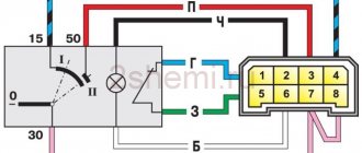
Good day everyone! Forgive me if the topic is button accordion, but there is no one else to ask. Question - I have an engine 2110 engineer, I bought high-voltage wires and foolishly removed the old ones, but I didn’t remember the connection sequence. If I am facing the car, then the numbering of the candles is 1 2 3 4? But how do they all connect to the square ignition module? If anyone knows, please explain or draw a diagram, please.
Attached images
Post edited by Kiel Blinton: 12/05/2010 - 18:03
Advertisements on NN.RU - Auto
A specialized company for converting trucks into tow trucks invites you to install a tow truck platform on.
The company offers you to upgrade the Fiat Ducato Fiat Ducato basic version for a solution.
Power take-off boxes Kamaz, Maz, Ural, Kraz, Gas, Zil Dispatch on the day of payment. Sending by transport companies. We work as with. Price: 18,500 rub.
With us you can not only extend the frame to fit a body of 5.1 m, 6.2 m, 7.5 m, 9 m for Maz Zubrenok, Maz, Kamaz, Ural, Zil, Mitsubishi, Nissan.
Today, Nizhny Novgorod fast food lovers have a real holiday: a new worldwide outlet has opened on the renovated Nizhne-Volzhskaya embankment.
An accident occurred in the Moskovsky district of Nizhny Novgorod: a girl was swinging her friend, but the swing suddenly fell. As a result.
A street film festival will be held in Nizhny Novgorod for the second time. Short films by young Russian directors will be available for free.
Imagine, you wake up in the morning, open the curtains, bright sunlight bursts into your apartment, and outside the window is a stunningly beautiful landscape.
Source
Sereshka 05.12.2010 - 18:01
Kiel Blinton (05.12.2010 - 17:56)
:
Good day everyone! Forgive me if the topic is button accordion, but there is no one else to ask. Question - I have an engine 2110 engineer, I bought high-voltage wires and foolishly removed the old ones, but I didn’t remember the connection sequence. If I am facing the car, then the numbering of the spark plugs is 1 2 3 4. But how are they all connected to the square ignition module? If anyone knows, please explain or draw a diagram, please.
There should be numbers on the module itself.
Diagram of injection VAZ 2110 8 valves
| 1 – block headlight | 2 – front brake pad wear sensors | 3 – sound signal |
| 4 – cooling system fan | 5 – reverse light switch | 6 – battery |
| 7 – generator | 8 – oil pressure warning lamp sensor | 9 – oil level sensor |
| 10 – spark plugs | 11 – nozzles | 12 – idle speed regulator |
| 13 – electronic control unit blocks | 14 – throttle position sensor | 15 – crankshaft position sensor |
| 16 – ignition module | 17 – coolant temperature indicator sensor (for instrument cluster) | 18 – starter |
| 19 – diagnostic block | 20 – coolant temperature sensor (for engine management system) | 21 – speed sensor |
| 22 – fuel pump activation relay | 23, 35, 39 – fuses | 24 – electric fuel pump |
| 25 – micromotor gearbox for heater damper drive | 26 – recirculation valve | 27 – heater fan |
| 28 – windshield washer pump | 29 – washer fluid level sensor | 30 – brake fluid level sensor |
| 31 – coolant level sensor | 32 – windshield wiper gear motor | 33 – additional heater fan resistor |
| 34 – injection system power supply relay | 36 – adsorber purge valve | 37 – mass air flow sensor |
| 38 – relay for turning on the cooling fan | 40 – external lighting switch | 41 – knock sensor VAZ-2110 injector |
| 42 – oxygen concentration sensor (heated lambda probe) 42* – CO potentiometer (installed on cars running on leaded gasoline; in this case, an oxygen concentration sensor is not installed) | 43 – fog light indicator lamp | 44 – indicator lamp for heated rear window |
| 45 – fog light switch | 46 – rear window heating switch | 47 – instrument cluster |
| 48 – mounting block | 49 – fuel level sensor | 50 – ignition switch |
| 51 – instrument backlight brightness control | 52 – steering column switch | 53 – backlight lamp for heater control levers |
| 54 – hazard warning switch | 55 – electronic heater control unit; | 56 – recirculation valve switch |
| 57 – display unit of the on-board control system | 58 – side direction indicators | 59 – temperature sensor for the heating system |
| 60 – interior lamp | 61 – front interior lamp | 62 – socket for a portable lamp |
| 63 – electronic watch | 64 – switches in the front door pillars | 65 – switches in the rear door pillars |
| 66 – glove box lighting lamp | 67 – glove box lighting switch | 68 – cigarette lighter |
| 69 – ashtray lighting lamp | 70 – brake light switch | 71 – rear window heating element |
| 72 – external rear lights | 73 – internal rear lights | 74 – license plate lamps |
| 75 – trunk lighting lamp |
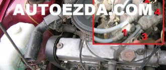
Location
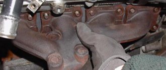
On VAZ 2110 injection engines, high-voltage wires are attached at one end to the ignition coil, which is located on the front side of the cylinder block slightly to the right of the center, and the other end is connected to the spark plugs. On carburetor engines, the circuit is exactly the same, only instead of a coil, the wires go to the distributor, which is installed to the right of the cylinder head.
Preparatory activities and necessary tools
Installing the ignition of a VAZ 2109 carburetor begins with preparatory activities. In particular, you need:
- Warm up the car engine;
- Set the parking brake and install wheel chocks under the rear wheels.
Remember that you cannot ignore safety rules, because a car is a highly dangerous vehicle, and failure to comply with safety rules when driving, servicing and repairing it can cost you dearly.
An important point: before you start work, you should make sure that the carburetor is correctly configured on the car. It would be a good idea to carry out a visual inspection of all elements of the system.
If we are talking about a carburetor car, special attention should be paid to inspecting the condition of the distributor
If you have a car with an injection engine, it is worth checking the ignition module for serviceability. The thing is that, as practice shows, it is this module that fails most often and is the reason for the inoperability of the entire system.
To complete the work we need:
- strobe;
- a set of keys.
Sn00pi › Blog › How to check BB wires? Troubleshooting.
How to check high voltage ignition wires?
Automotive high-voltage (HV) wires play an important role for internal combustion engines, since they help transmit high current from the ignition coil to the spark plugs. The serviceability and efficiency of the wires determines the timeliness and intensity of ignition of the fuel-air mixture, and therefore the correct and uninterrupted operation of the engine. Despite their simplicity, wires have many different “sores” and can cause a lot of troubles to their owner, which in one way or another will affect his nerves and pocket.
Malfunctions of high-voltage wires (common problems):
As a rule, the malfunction boils down to the fact that current either does not flow to the spark plug at all, or it does, but in limited quantities. This can happen for the following reasons: — There has been a break in the current-carrying wire through which the pulse travels. — There is a current leak, that is, the insulation is damaged and the current flows to the side. — The resistance exceeds the permissible value. — Problems in contacts (with a spark plug or ignition coil).
In the event of a break in the current-carrying wire, the effect of an internal spark occurs, in other words, an electrical discharge is formed between the ends of the broken wire, which reduces the voltage and causes an electromagnetic parasitic pulse. This impulse, in turn, negatively affects the correct operation of many of the vehicle's sensors. One such damaged high-voltage wire can cause vibration and interruptions in engine operation. Due to a damaged high-voltage wire, ignition in the cylinder occurs late or every other time, as a result, the synchronous operation of the cylinders and the engine as a whole is disrupted.
How to check high-voltage wires? Effective ways:
First of all, it is necessary to check the explosive for the absence of visible damage (cracks, fractures, etc.). Make sure there is no breakdown, this can be determined even without instruments, just look under the hood in the dark; in the event of a breakdown while the engine is running, a spark will be visible on the explosive wire. You can check high-voltage wires using a wire. To do this, you need to take a piece of wire in the dark and strip it on both sides. Then one end must be shorted to ground (machine body), and the other end must be drawn along the entire length of the explosive wires, as well as joints, caps, etc. A spark will form at the breakdown sites.
This is interesting: What to do if your car is stolen?
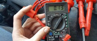
You can also check the resistance of the high voltage wires, for this you will need a multimeter. — Turn on the ohmmeter mode. — Remove the wire from the spark plug of the first cylinder and the ignition coil. — Connect the multimeter electrodes to the ends of the wire and look at the readings.
In good wires, the resistance should vary from 3.5 to 10 kOhm, depending on the type of wires themselves. Information about resistance is most often indicated on the insulation of high-voltage wires. Check each wire, the spread between them should not exceed 2-4 kOhm. If there is a large variation, replace the wires. By the way, they are changed as a set, that is, all together.
To complete your reading of the resistance of the most popular high-voltage wires: Tesla - 6 kOhm Slon - from 4 kOhm to 7 kOhm (4 kOhm - 1st cylinder and up to 7 kOhm - on the last cylinder) ProSport - almost zero resistance Cargen - 0.9 kOhm
Note! The resistance of high-voltage wires varies depending on the length, thickness, and material from which the wires are made.