Table with errors
A complete list of faults with explanations and recommendations for troubleshooting:
| Error | Sensor malfunctions |
| P0030 | Code P0030 (0030) indicates a malfunction of the oxygen control controller. The problem was detected by the engine control unit as a result of driver diagnostics. To fix the problem, you need to check the electrical circuit of the heating element for a break. |
| P0032 | Code P0032 indicates a short circuit in the control circuit of the heating element of the lambda probe to the on-board network |
| P0036 | Combination P0036 (0036) appears as a result of a malfunction in the electrical circuit that supplies the heating element of the oxygen controller. This refers to a sensor installed after the neutralizer device. The error indicates an open circuit, so first of all you need to check its integrity. |
| P0102 | Code P0102 (0102) indicates a malfunction of the mass air flow controller. The cause of the malfunction is damage to the flow meter wiring. The error may be intermittent, so to fix it, you need to try cleaning or replacing the air filter. The cause of the problem may be damage to the wiring on the microprocessor module connector. To check the flow meter, perform the following steps:
|
| P0103 | The control unit has detected an incorrect signal coming from the mass air flow sensor. Electrical circuit diagnostics required. |
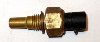
| P0112 | Code 0112 indicates problems with the incoming air temperature controller. It is necessary to check the operation of the sensor, as well as its wiring. |
| P0113 | Code P0113 (0113) appears as a result of incorrect operation of the incoming air temperature controller |
| P0116 | Combination 0116 is associated with an incorrect signal coming from the coolant temperature sensor. The reason may lie directly in the regulator or the integrity of the power line. |
| P0117 | Incorrect signal from antifreeze temperature regulator |
| P0118 | Error P0118 (0118) appears as a result of an increased signal recorded on the refrigerant temperature sensor line |
| P0122 | Code P0122 (0122) is a consequence of an incorrect pulse supplied from the throttle position sensor. There may be interference in the circuit if the line is damaged. |
| P0123 | The microprocessor module has detected that the throttle position controller is sending an incorrect signal. The pulse is out of range. A detailed check of the wiring is required, as the cause may be damage. |
| P0130 | Combination P0130 (0130) appears as a result of damage to the electrical circuit of the control oxygen controller. Possible short circuit of contacts. |
| P0131 | Code 0131 reports low voltage in the electrical circuit of the oxygen control controller |
| P0132 | Combination 0132 indicates an increased voltage signal coming from one of the control oxygen controllers |
| P0133 | Code 0133 literally translates as “diagnosis of a slow response from the control oxygen sensor.” The problems are related to the signal coming from the device. |
| P0134 | Combination P0134 (0134) appears as a result of a decrease in voltage in the electrical circuit of the control lambda probe |
| P0135 | Combination P0135 (0135) is associated with damage to the heater of one of the oxygen controllers. The reason may be a faulty electrical circuit. |
| P0140 | Code 0140 indicates a lack of activity in the power line of the oxygen controller installed after the converter |
| P0222 | Second throttle position sensor voltage too low |
| P0325 | Code P0325 (0325) is associated with an open circuit in the detonation controller |
| P0326 | Code P0326 (0326) appears as a result of the signal supplied from the knock regulator being outside the normal range |
| P0327 | Code P0327 (0327) indicates a reduced signal level coming from the knock controller. It is necessary to check the quality of the sensor's connection to the network. |
| P0328 | Combination P0328 (0328) reports an excess of the signal coming from the engine knock sensor. If the controller is faulty or there is a break in the electrical circuit, the problem may be accompanied by unstable operation of the engine and its random stopping. |
| P0336 | Code 0336 indicates a breakdown of the crankshaft position sensor or damage to its wiring. |
| P0337 | Code 0337 appears as a result of a short to ground in the crankshaft position controller. It is necessary to check the contacts and wiring of the sensor. |
| P0340 | Code P0340 (0340) indicates problems with the camshaft position sensor. The signal coming from the controller does not change in a car with the engine running. If the dashboard shows this error, the user needs to diagnose the sensor electrical circuit. Since the regulator is installed in the engine compartment, the contact on its wiring connector could be clogged. |
| P0341 | Error P0341 (0341) appears as a result of failure or malfunction of the camshaft position sensor |
| P0342 | Code 0342 is associated with a faulty phase sensor. If the controller is faulty, the power unit may detonate during operation. The damaged wire is replaced, and the contacts on the regulator power connector are also cleaned. A failed sensor must also be replaced. |
| P0343 | Code number P0343 (0343) on an 8- or 16-valve Priora with BC (on-board computer) State indicates a fault in the electrical circuit of the phase sensor. The signal coming from the controller is too high. A complete check of the device and its wiring is necessary; perhaps the cause is a short circuit. You may need a multimeter to troubleshoot. |
| P0346 | Malfunction of the phase sensor |
| P0500 | Combination P0500 (0500) appears when the speed controller is not operating correctly. The vehicle speed may be below the threshold. A detailed diagnosis of the signal coming from the regulator is required. |
| P0501 | Error P0501 (0501) indicates an incorrect signal coming from the speed sensor. If the device itself is working and its electrical circuit is intact, then to find the cause, detailed diagnostics of the microprocessor module will be required. |
| P0504 | Code P0504 (0504) appears as a result of a malfunction of the brake pedal controller. The on-board computer diagnoses the mismatch of pulses coming from the devices. Controller signals change inconsistently, which may indicate a malfunction or problems with wiring integrity. Most likely, the cause of the problem is contamination of the contact of the sensor installed on the pedal. |
| P0505 | Code 0505 indicates a malfunction of the idle speed controller. Failure of the regulator can cause a sharp jump in speed. |
| P0511 | Combination P0511 (0511) appears as a result of a malfunction in the idle speed sensor power line. It is necessary to completely check the wiring, test it and diagnose the contacts on the connector. The reason may be that the insulation on the main power cable is worn out. |
| P0830 | Error 0830 indicates a faulty clutch switch. It is necessary to check the operation of the sensor installed directly on the pedal; a wire break or damage to the connector is possible. The problem may be accompanied by increased fuel consumption and failures when shifting gears. |
| P1135 | Code P1135 (1135) The microprocessor module has detected a break or short circuit in the line of the heating element of oxygen sensor 1. The wiring integrity must be checked. |
| P1141 | The error is due to the inoperability of the heating element of the first lambda probe installed after the converter |
| P1513 | Combinations P1513 (1513) appear as a result of a short circuit on the idle speed controller line. Diagnostics of the contacts on the sensor connector is required. |
| P1514 | Code P1514 (1514) appears as a result of an open or short circuit in the wiring of the idle speed sensor. It is necessary to check the integrity of the pins on the block and ring the electrical circuit. A faulty controller must be replaced. |
| P1617 | Code 1617 indicates an increased signal level in the electrical circuit of the rough road controller. In general, this error will not affect the operation of the engine in any way. |
| R2020 | Combination 2022 is associated with a malfunction of the intake shaft flap position controller |
| P2122 | Code P2122 is associated with a reduced signal from the gas pedal position sensor |
| P2127 | The voltage in the electrical circuit of the gas pedal position controller is below the permissible value |
| P2138 | Error P 2138 appears as a result of checking the mismatch of pulses received from two gas pedal controllers. The voltage level in the sensor electrical circuit does not correspond to the standardized value. |
| Code | Engine malfunctions |
| P0101 | Error P0101 (0101) indicates that the air flow readings from the sensor are incorrect. Detailed diagnostics of the controller is required; it may need to be cleaned. |
| P0121 | Open circuit of the third injector. With this problem, the engine may not operate correctly. |
| P0171 | Code P0171 (0171) indicates a malfunction in the fuel supply system. The error appears as a result of a lean combustible mixture. |
| P0172 | Codes P0172 (0172) indicate that the air-fuel mixture is rich. It is necessary to check not only the engine cylinders, but also the elements that influence its formation. This refers to the air filter and flow meter. The cause of the problem may be a lack of tightness. |
| P0204 | If on a VAZ Euro it was possible to read VDO code 0204, this indicates a break in the wiring in the electrical control circuit of the fourth cylinder injector. |
| P0300 | If error P0300 (0300) occurs, the control unit reports that the threshold value for misfire of the air-fuel mixture has been exceeded. It is necessary to accurately check their number. |
| P0301 | Code P0301 (0301) appears as a result of misfire in the first cylinder of the engine |
| P0302 | Misfire in the second cylinder of the power unit. It is necessary to check the operation of the mass air and oxygen flow sensors. |
| P0303 | Code P0303 (0303) indicates detection of misfire in the third cylinder of the engine |
| P0304 | The appearance of error P0304 is also associated with misfires for toxicity. Their number is significantly higher than the nominal threshold. |
| P0335 | Code P0335 (0335) indicates a crankshaft (crankshaft) synchronization error. The first thing to do is check the operation of the crankshaft controller and its wiring. |
| P0363 | Code P0363 (0363) indicates a misfire in one of the engine cylinders. The ECU (electronic control unit) has cut off the fuel supply to the idle cylinders. Possible causes of the problem:
If replacing the fuel does not help, it is necessary to diagnose the air intake system. You should tighten the fastening clamps, change the air filter element and check the pressure in the rail (the normalized value is no more than 2.8 atm). It is also necessary to perform diagnostics:
Diagnostics of high-voltage wires is carried out using a tester; it is necessary to check the resistance. If the obtained value is more than 10 kOhm, then the cables must be replaced. You also need to check the integrity of the spark plugs and make sure there is no carbon deposits on their tips. If the described actions do not help determine the cause, the cylinders are diagnosed. The user needs to check the compression level, which should be approximately the same in each device. If the obtained values differ by more than 0.5 atm, then the power unit needs to be tested in more detail. |
| P0422 | Combination P0422 (0422) indicates a malfunction of the neutralizer device. Literally, the code can be deciphered as “determining the oxygen capacity by comparing the amplitude range of two lambda probes - diagnostic and oxygen.” In other words, the aging coefficient of the neutralizing device is greater than the upper maximum value. It is necessary to check the operation of the sensors and replace them if necessary. The cause of the problem may be poor contact between the controllers and the network. |
| P0441 | Combination P0441 (0441) literally stands for “incorrect response of the idle speed support system, the value is higher or lower than the threshold.” The malfunction indicates problems in the operation of the canister purge valve. It is necessary to diagnose the device and clean it; if this does not help, the mechanism should be replaced. |
| P0443 | Code P0443 (0443) reports a malfunction in the electrical circuit for controlling the adsorber purge valve |
| P0444 | Driver diagnostics showed a break in the electrical line of the canister purge valve |
| P0485 | Malfunction of the engine cooling fan - the voltage level on the line is less than or greater than the threshold value. It is necessary to diagnose the signal coming from the device. The cause of the problem may be oxidation or clogged contacts on the fan power connector. |
| P0506 | Reduced idle speed of the power unit |
| P0507 | Combination P0507 (0507) indicates increased speed of the power unit in the idle system. The cause of the problem may be the sensor or its wiring. |
| P1140 | Combination 1140 literally stands for “measured engine load differs from calculation.” There can be many reasons for this problem, ranging from incorrect compression to malfunctions in the microprocessor module. |
| P1301 | The appearance of error P1301 (1301) is associated with the excess number of misfires to protect the converter. A decrease in quantity may negatively affect the functioning of the latter. |
| P1302 | Code 1302 A large number of misfires in the ignition system to protect the neutralizer device |
| P1303 | A misfire was detected in the third cylinder of the engine, which may affect the operation of the converter. |
| P1304 | Code 1304 appears as a result of misfire in the fourth cylinder of the engine. |
| P1335 | Error P1335 literally stands for “throttle valve actuator control monitoring: position out of range.” Possible causes of the problem:
To fix the problem, you can try to relearn the throttle valve, to do this, perform the following steps:
|
| P1426 | Combination P1426 (1426) indicates a break in the control line of the canister purge valve |
| P1545 | The throttle valve position is outside the operating range. It is necessary to clean the mechanism and adapt it if necessary. It is also necessary to check the connector and damper operating parameters using diagnostic equipment. If these steps do not help resolve the problem, you need to contact specialists to flash the microprocessor module or perform this task yourself. |
| P1578 | Error 1578 can be literally translated as “zero adaptation parameter is out of range.” Possible solutions to the problem:
|
| P1602 | Code P1602 (1602) means a loss of voltage in the power supply circuit. With this problem, the engine often does not start because the starter is not receiving power. The Multitronics computer may be faulty, but first of all you need to check the battery charge. The problem may be due to a broken generator set. |
| P2135 | The appearance of code P2135 (2135) is associated with malfunctions in the functioning of the throttle mechanism. It is necessary to check the sensor and the damper; perhaps it is stuck in the open or closed position. If the node itself is operational, a check of the microprocessor module is required. |
| P2187 | Combination P2187 appears when the air-fuel mixture in the engine cylinders is lean |
| P2188 | With error P2188, the engine control unit reports that the air-fuel mixture is over-rich when the power unit is idling. A detailed diagnosis of the fuel supply system is required. |
| P2304 | Increased current in the electrical circuit of one of the ignition coils |
| Code | Electrical faults |
| P0351 | Code P0351 (0351) appears as a result of a break in the electrical control circuit of the ignition coil of the first cylinder. When this combination appears, the following problems are possible:
|
| P0352 | Broken or damaged ignition coil control wiring installed on the second cylinder |
| P0480 | Combination P0480 indicates an open circuit in the engine cooling fan relay |
| P0560 | Error P0560 (0560) appears due to voltage surges in the vehicle's electrical network |
| P0562 | Combination P0562 (0562) indicates low voltage in the vehicle's electrical network |
| P0563 | Increased voltage in the vehicle's on-board network. It is possible that the car's battery is severely discharged and the generator unit is working in increased mode to compensate for the discharge. Diagnosis of the battery as well as the generator is required. In the latter, the regulator relay may be faulty. |
| P0601 | The appearance of error 0601 is due to a malfunction of the permanent memory module of the motor control unit |
| P0603 | Code P0603 indicates a malfunction of the RAM module in the engine control unit. It is necessary to check the connectors on the main block of the module, as well as diagnose the integrity of the contacts. Reflashing the microprocessor will help eliminate the cause if the problem is non-mechanical in nature. |
| P0615 | Driver diagnostics showed an open circuit in the starter relay |
| P0628 | Code 0628 is associated with a short circuit in the fuel pump relay circuit during driver diagnostics. A detailed check of the wiring is required, as well as the socket in the fuse box. If the fuel pump relay is faulty, the engine will not be able to start. |
| P0650 | Code P0650 indicates a malfunction of the lamp indication circuit |
| P1336 | Code 1336 literally means “the controller type does not match the standard one.” Most likely, the reason is poor contact of the main relay; it is necessary to bend its legs. |
| P1425 | Code 1425 - short circuit to ground in the electrical circuit of the canister purge control valve |
| P1541 | This error is associated with damage to the fuel pump relay control circuit. |
| P1570 | Damage to the immobilizer control circuit. It is necessary to check the cable powering the device; a possible reason may be the antenna. |
| P1600 | No communication with the immobilizer. The problem may not manifest itself in any way in terms of symptoms. |
| P1603 | Malfunction of the internal microprocessor memory module |
| P1612 | Electronic control unit processor memory reset error. Possible signs of problems:
Detailed diagnostics of the microprocessor module and its flashing if necessary are required. |
| P1620 | Combination 1620 indicates a malfunction in the internal memory module of the control unit |
| P1621 | The combination P1621 (1621) indicates a problem with the RAM module. It is necessary to check the microprocessor module for errors. |
| P6060 | Code 6060 indicates a malfunction of the processor device. If the problem is of a software nature, then the problem should be “treated” only by flashing the module. If you do not have the appropriate equipment and skills, you can follow these steps to resolve:
|
| B2AAA | Code B2AAA is a general malfunction of the body control module. There can be many reasons for the problem; most likely, a wire has come loose on one of the connectors. |
| U3FFF | Problems with the engine control unit. The reason may be moisture getting into the wiring supplying the control module. |
| Code | Self-diagnosis errors |
| 1 | Engine control unit malfunction. If, when reading, the module showed this error on a 2110 16 cl or another VAZ, to solve it you need to look at the device block. Most likely, the reason is oxidation of the contacts or damage to the connector. If the control unit malfunctions, the module is flashed. |
| 2 | The voltage in the on-board network is too high. The user needs to check the operation of the battery and generator unit. |
| 3 | Malfunction of the electrical circuit of the fuel level sensor. The device may emit a low or high signal. It is necessary to check the sensor and the electrical circuit that powers it. |
| 4 | Antifreeze controller malfunction. It is necessary to diagnose the sensor and wiring. |
| 5 | External temperature controller error. |
| 6 | Overheating of the power unit. |
| 7 | Emergency engine fluid pressure |
| 8 | The vehicle voltage is too low. Diagnostic steps are similar to the high voltage test. |
| 9 | The battery is discharged (the criterion for triggering the acoustic alarm is met) |
| E | Determining an error in a data packet stored in EEPROM |
| 12 | Malfunctions in the functioning of the diagnostic electrical line of the indicator located on the instrument panel. |
| 13 | The microprocessor module does not receive an impulse from the lambda probe |
| 14 | The control unit detects an increased signal coming from the antifreeze temperature sensor |
| 15 | Coolant temperature controller malfunction. The device outputs a reduced signal that does not correspond to the nominal value. |
| 16 | Increased voltage in the vehicle electrical network |
| 17 | Low voltage in the on-board network |
| 19 | Malfunction of the crankshaft position sensor. An incorrect signal is supplied to the microprocessor module from the controller. It is recommended to diagnose the connector and contacts; it is possible that dirt has got on the block. |
| 21 | Malfunction of the throttle valve position regulator. The problem may be with the node itself. It is recommended to check the operation of the controller and its wiring. |
| 22 | Reduced signal coming from the throttle position controller |
| 23 | The signal coming from the intake air temperature controller is too high |
| 24 | Vehicle speed sensor malfunction. The speedometer may be showing incorrect readings. To fix the problem, you need to check the contacts on the European instrument panel; perhaps the connector is simply coming off. |
| 25 | Too low signal detected in the electrical circuit of the intake air temperature sensor |
| 27, 28 | Incorrect pulse coming from the exhaust gas sensor |
| 33, 34 | Problems with the flow meter. It is necessary to check all contacts and the electrical circuit through which the mass air flow controller is connected. |
| 35 | The microprocessor module has detected a deviation in idle speed, the reason may be a sensor malfunction |
| 41 | Incorrect signal coming from the phase regulator |
| 42 | Damage to the electrical circuit of the electronic ignition system |
| 43 | Incorrect pulse coming from the knock sensor |
| 44, 45 | The mixture in the engine cylinders is too lean or rich |
| 49 | Vacuum leak, requires diagnostics of all lines and tightness check |
| 51, 52 | Malfunction of one of the control unit memory modules - RAM or PROM |
| 53 | The control unit cannot detect the signal coming from the exhaust gas sensor |
| 54 | Lack of impulse supplied from the octane corrector regulator |
| 55 | Leaning of the air-fuel mixture at low load on the car engine |
| 61 | Lambda probe malfunction |
| Code | Three-digit combinations |
| 102 | Malfunction of the mass air flow sensor. A possible cause of the problem may be a clogged device; sometimes cleaning the controller can eliminate it. |
| 131 | One of the oxygen controllers is faulty. A detailed check of all sensors, their contacts, as well as heating devices is required. |
| 134 | No signal from the oxygen controller. The sensor number is not indicated, nor is its location, so you need to check each device. |
| 171 | Lean mixture in the cylinders of the power unit |
| 300 | The microprocessor module detected random or multiple misfires in the engine cylinders |
| 327 | Low level of signal recorded in the electrical control circuit of the detonation controller |
| 328 | The signal detected in the knock sensor control circuit is too high |
| 343 | Malfunction of the camshaft position sensor, increased signal coming from the device |
| 501 | Speed controller malfunction |
| 504 | Incorrect signal coming from the brake pedal adjuster. It is necessary to check the sensor contacts for integrity of the pins and clogging of the connector. |
| 422 | Low efficiency of the catalyst device. The cause of the problem may be a leak in the system. |
| 441 | Incorrect air flow through the canister purge valve. The appearance of this code may be due to the following conditions:
|
| 603 | External RAM module error |
| 830 | Malfunction of the controller installed on the clutch pedal |
| Code | Composite Combinations |
| 3456, 78, 78E | These codes on BC M74 on VAZ 11183 or 212140 mean individual errors, for example 3456 - 3, 4, 5 and 6. |
Decoding of VAZ error codes is presented for the following models:
- 1118 Kalina (Kalina);
- 2104;
- 21041;
- 2105;
- 2107;
- 21074;
- 2109;
- 21093;
- 21099;
- 2110;
- 21102;
- 21103;
- 2111;
- 2112;
- 2113;
- 2114;
- 21114;
- 21124;
- 2115 with engine injector 8 and 16 valves;
- 21150;
- 21154;
- 2131;
- 2170 Priora (Priora);
- 2190 Granta (Grant);
- 2123, 21214, 2131 Niva (Niva);
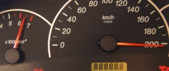
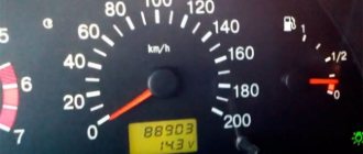
Self-diagnosis mode VAZ 2110
We will tell and show the self-diagnosis mode of the instrument panel of the VAZ 2110 2112 2111, we will decipher the error codes of the VDO panel.
In order to start the self-diagnosis mode of the instrument panel, you need to turn the key in the ignition and simultaneously hold down the daily mileage reset button. When the mode is turned on, all the arrows must reach “the end” and return back, in this way you can check the functionality of all sensors, instruments, light bulbs, and the arrows themselves. Then we press the mileage reset button once again, the firmware version will be written in the information window, in our case it is 1.1, we press our button again and see the error codes. To reset errors, press the button and hold for a while: The number “0” that appears on the screen indicates that all errors have been reset. We repeat the entire procedure again from the very beginning to make sure that we have no errors.
Decoding VDO error codes:
0 means there are no errors at all. 1 microprocessor is faulty. 4 means that the supply voltage of the on-board network is higher than 16 Volts; 8 error, on the contrary, shows a low voltage, less than 8 volts. The following errors may appear: 6, 10, 12, 14 - they mean several malfunctions at the same time, i.e. are summed up, 6 (this is 2+4), etc.
To be honest, these readings are of little use; the simplest diagnostic device will show much more and in all details. The additional on-board computer also displays all the main errors; we take readings from all systems.
Video of the self-diagnosis mode of the instrument panel VAZ 2110 2112 2111:
Hello dear visitors of the site vaz2110-remont.ru. The topic of this article will be diagnostics of the tidy on the VAZ 2110, 2111, 2112.
In order to start the self-diagnosis mode of instrument clusters, you must turn on the ignition while holding down the button that resets the daily mileage.
How to understand that the mode has started? Everything is very simple, the oil pressure lights, the battery icon, the fuel warning light and the Chek light will start to light up. In this case, all arrows begin to move from the initial position to the maximum, and this process is repeated. This way you can check the operation of all light bulbs, instruments, and arrows.
Go ahead and press the button to reset the daily mileage. In this case, the arrows return to their initial position, and the firmware version will appear on the on-board computer screen. In our case, this is version 1.1.
When we press the button to reset the daily mileage, an error code will appear.
To reset this error, you need to press and hold the button that resets the daily mileage. Until the error resets to 0.
To check that the errors have been reset, we repeat the procedure: enter the mode - diagnostics of the VAZ 2110 device (while turning on the ignition, press and hold the button that resets the mileage); Press the mileage reset button three times and look at the on-board screen. It should show 0.
We decided on this. But now we need to find out what kind of error we identified during the self-diagnosis of the instrument clusters. A table is presented to you for this purpose.
| The error code shown by the on-board computer | Malfunction |
| No faults | |
| 1 | Microprocessor malfunction |
| 2 | The circuit from the sensor responsible for the fuel level indicator is broken |
| 4 | The power supply in the on-board network exceeds 16 V |
| 8 | Power supply in the on-board network is below 8V |
If the number is different, for example, like ours, this means that there are several errors and the computer shows their sum: 6 (2+4), 10 (2+8), 12 (4+8), 14 (2+4+ 8).
You can watch the whole process in the video below:
We have sorted out the errors during self-diagnosis of the instrument clusters of the VAZ 2110, but here you can see how to reset the Check error (when the engine light comes on) yourself.
Published on August 29, 2016
I'm getting error 79.0, what is this?? And tell me how to fix it
When I press a button and turn the key, nothing happens, what could it be?
vdo 2110 old model with one window the problem is this:
All the lights are on, but none of the instruments work and there are no numbers, but when the dimensions are turned on, the window lights up, what could be the problem?
VAZ2112 speedometer lies at 10-20 km
When you release the reset button, the sasur eights disappear, what does that mean?
Great, I have a question for you. VAZ 2111 when I turn on the dimensions, they light up, i.e. everything is fine, I switch to low beam, the lights go out, the panel goes out, what’s the problem?
Hello, I have a 2000 2110, the tachometer constantly keeps 2000 rpm, they changed the idle speed sensor - it is useless. I think the computer, how can I reset the settings on 2000 machines? - Thank you
I can’t press it like that and there’s no reset, can you tell me what the problem is?
hi, I tried to do it like in the video on a VAZ 2112 2002, what do you think is the reason?
Greetings. I did a diagnostic on the instrument panel, showed firmware 1.1 and error number 8 popped up. And even before that, error 14 popped up. What kind of errors are these and how to fix them so that I don’t have them
Hello, my VAZ 2110 also has error 14 like in your video (High signal level of the coolant temperature sensor) what does this mean and what needs to be changed
Thank you for the informative and necessary video.. For those interested, see ERROR CODES https://www.drive2.ru/c/1046771/
It also works on 4 (16V)
It also works on 4 (16V)
Question! if possible please help. VAZ 2112. My camshaft sensor is not connected to the brains of the car. So, the sensor itself is connected and the car drives and works normally (as for me), but the check engine constantly lights up. I bought the connection socket itself. But here’s the problem, there is only one wire for connection - brown, it is not clear what to connect two more wires to, since I don’t see any more broken wires, and two more wires come out of the connection socket. It is impossible to find a normal auto electrician in my city. How to connect the sensor correctly, how to determine what to connect to what, and where to look for torn wires?
How to diagnose the error?
It is important to know
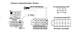
There are two options for diagnosing a VAZ car - testing using the instrument panel and using a computer. The second option is considered more accurate, but its implementation will require a special program and a cable for connecting to the diagnostic connector.
Checking using a computer is done like this:
- The diagnostic wire is connected to the laptop. Its second end must be connected to the OBD2 connector in the Lada car. The location of this block differs depending on the car model; this nuance must be clarified in the service manual.
- A diagnostic program is launched on the computer, which allows you to decipher error codes. To start the test, press the corresponding button.
- The diagnostic process begins. Depending on the utility, the program can separately check the operation of the engine, transmission or electronics.
- After the test is completed, combinations of faults will appear on the computer screen that need to be deciphered. Depending on the program, a description of the error may also be displayed immediately.
Diagnostics using the dashboard is performed as follows:
- The car owner sits in the driver's seat and presses the daily mileage reset button on the odometer.
- The key is inserted into the lock and scrolled to the “ACC” position.
- The daily mileage reset button is released. The arrows on the speedometer, tachometer, and sensors will begin to quickly move from the minimum position to the maximum.
- The odometer key is pressed and released. An inscription with the software version will be displayed on the instrument cluster screen.
- After the third press of the odometer key, combinations of faults will appear on the screen.
Video: diagnosing a VAZ using the dashboard
The CarFance channel in its video showed in detail the process of testing a Lada car using a control combination.
Diagnostics using a scanner
The method involves connecting an external computer with the program installed. This opens up more opportunities for car diagnostics. In this case, error codes for VAZ 2110 and VAZ 2112 consist of 5 characters.
Letter part:
- P – failure or malfunction of the power plant, transmission;
- B – body systems are damaged;
- C – a problem has been detected in the vehicle’s chassis;
- U – violation of pairing of different modules.
First digit:
- 0 – general value;
- 1/2 – manufacturer code;
- 3 – reserve.
Second digit:
- 1-2 – violation in the air-fuel mixture supply devices;
- 3 – malfunction of the ignition units;
- 4 – atmospheric emissions control device;
- 5 – malfunction of the engine speed or engine speed meters;
- 6 – failures in electronics;
- 7-8 – malfunction of the gearbox module;
- 9-0 – reserve unit.
The last two digits give the serial number of the breakdown and its location.
How to reset the error?
Good to know
You can delete the error code from the memory of the VAZ control unit by disconnecting the terminal from the battery.
The reset procedure is performed as follows:
- The vehicle's ignition system is activated, but the power unit does not start.
- The engine compartment of the vehicle opens. Using a wrench, loosen the screw that secures the terminal clamp on the negative output of the battery.
- After about one minute the contact is reconnected.
- The engine compartment of the car is closed, the ignition system in the car is turned off.
- The car engine is starting. If the “Check” indicator remains lit on the dashboard, it should disappear on its own after a few kilometers.
Prevention of breakdowns of electrical appliances
To prevent breakdowns of electrical circuits, you must follow a number of simple rules.
- Periodically check the contact connectors for oxidation or overheating. Rust disrupts the passage of impulses, which can be read by instruments as damage to the unit.
- Once a year, treat contacts with special oils. Lubricants prevent moisture from entering metals, which prolongs their service life.
- Replace dry wires in a timely manner. Cracked insulation can cause a short circuit.
Errors on the VAZ 2110 (2112) panel provide the user with complete information about the condition of the vehicle’s components and assemblies. If you know the decryptions, the driver can independently fix the breakdown of the vehicle electronics.
Source
The cost of diagnosing errors for VAZ at service stations in Moscow and St. Petersburg
Approximate prices for computer diagnostics:
| City | Company name | Address | Phone number | Price |
| Moscow | North Motors | St. Dubninskaya, 83 | +7 | 2500 rub. |
| Silver elephant | St. Pyalovskaya, 7 | +7 | 3500 rub. | |
| Saint Petersburg | Automagic | St. Uchitelskaya, 23 | +7 | 2000 rub. |
| ClinliCar | Bolshoy Sampsonievsky Ave., 61k2 | +7 | 3000 rub. |
Excerpt from open sources
2 - Excessive voltage. 3 - Fuel level sensor error*. 4 — Coolant temperature sensor error*. 5 — Outside temperature sensor error**. 6 — Engine overheating***. 7 - Emergency oil pressure***. 8 - Brake defect***. 9 - Low batteries***. E - Recognition of an error in a data packet stored in EEPROM.
Note: * – an error is registered if within 20 seconds. a sensor break is detected; ** – an error is registered if within 20 seconds. The actual sensor data is not recognized (indication on the LCD is “— °C”); *** – accompanied by an acoustic signaling device.
Source
Designation of icons on the dashboard of Lada 2112
| Number in photo | Interpretation of lamps and indicators |
| 1 | Coolant temperature indicator; if the light comes on at the top of the scale, the engine has overheated. |
| 3/4 | The turn signal indicators light up simultaneously when the hazard lights are turned on. |
| 7 | Empty tank indicator; if the lamp lights up, stop at a gas station. |
| 8 | External lighting is turned on and operating normally. |
| 9 | The pressure in the brake system has dropped. It is necessary to immediately add fluid to the expansion tank of the system. |
| 10 | The high beam headlights are activated. |
| 12 | The odometer display shows non-resettable mileage. |
| 13 | The hazard warning lights are on. |
| 14 | The engine control system is damaged or not working correctly. |
| 15 | The battery is not receiving a charge. In this case, you should check the battery itself for wear and the generator set. |
| 16 | The handbrake is activated. |
| 17 | The oil pressure in the engine crankcase has dropped below normal. You should add fluid to the specified level and check the operation of the pump. |
| 18 | In a configuration with an airbag, it indicates that the squib drive is turned off. In other versions the light bulb is a backup one. |
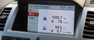
What standard trip computers exist?
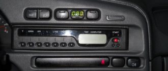
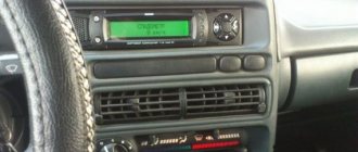
Option 1. In the instrument cluster.
Option 2. Installed instead of a small plug next to the ACS unit
These were installed on “luxury” dozens.
There are models AMK 211000 without diagnostics, and AMK 211001, AMK 211002 with diagnostics. You can find out which one you have by looking at the numbers on the back cover. To do this, naturally, the MK must be removed. If on the back there are the inscriptions AMK-211001 or AMK 211002, and in clock mode, when you press the “clock” button, the inscriptions Err appear and then two more - great. You have a full-fledged bookmaker. If these are the inscriptions:
Unfortunately, this is a BC that either lacks diagnostic capabilities or has “cut-off” firmware.” Craftsmen resolder and reflash such models, but in my opinion they are not worth it.
It is very easy to remove such a MK. We disconnect the terminal of the “negative” wire from the battery terminal. We pry it off with a screwdriver...
remove the MK from its seat....
....disconnect the wire block from it.
Designations on the MK screen
The trip computer (MC), shown in the figure, is installed in a variant version instead of a clock. MK has 15 functions, divided into 3 groups. The group is selected using buttons 1, 2 and 3.
In each group, functions are divided into basic and additional. The main functions are navigated through the ring using buttons 1, 2 and 3. Additional functions are navigated through button 5. When the ignition is turned off, the computer is always in the “Current Time” mode. When the battery is removed, the clock progress and all accumulated parameters are retained for at least 1 month.
ADJUSTING THE COMPUTER FUNCTION Correcting the clock rate Press button 4 in the “Current time” mode. At the sixth signal of the exact time, press button 1, this resets the seconds and rounds the clock readings.
Setting the current time (calendar) Press button 4 in the “Current time” (“calendar”) mode. Use buttons 5, 6 to set the desired hour (day). Press button 4. Use buttons 5, 6 to set the desired value for minutes (month). Press button 4 to complete the time (calendar) setting.
Click on the picture to enlarge.
Setting an alarm
Press button 4 in Alarm mode. Use buttons 5, 6 to set the desired hour value. Press button 4. Use buttons 5, 6 to set the desired minute value. Press button 4 to complete the alarm setting. In the “Current time” mode, the alarm symbol will light up (the alarm is on).
Turning off the alarm
Press button 4 in Alarm mode. Press button 1 to turn off the alarm. “—.—” will appear in the digital digits, and in the “Current time” mode the alarm symbol will not light up (the alarm is turned off).
Adjusting the brightness of the indicator backlight
When the side lights are on, the illumination level is adjusted using the instrument scale illumination regulator. When the side lights are turned off, the backlight level is adjusted by software: - press button 4 in the “Traveling time with stops” mode. All single segments (pictograms) will be displayed on the indicator, which is a sign of the backlight level adjustment mode, and the digital digits will display a number corresponding to the backlight level as a percentage of the maximum value; — use buttons 5, 6 to set the required level of backlight brightness; — press button 4 to end the brightness adjustment mode.
Calibrating the fuel level sensor
To carry out the correction, it is necessary to drain all gasoline from the tank. Press and hold button 4 for more than 2 s in the “Fuel level” mode. A flashing number “0” will appear on the indicator. Press and hold button 3 for 1 s until a confirmation beep appears. After this, a flashing number “3” will appear on the indicator. Fill the gas tank with 3 liters of gasoline using a measuring container, wait the time necessary for the fuel level sensor to calm down, press and hold button 3 for 1 s until a confirmation sound appears. Continue this procedure until the maximum value is 39 l, after which the computer automatically exits the mode.
Description of the buttons on the panel
| Number in photo | Purpose |
| 10 | Additional equipment control module. |
| 18 | Steering rack position regulator. |
| 19 | Hood lock drive. |
| 20 | Horn button. |
| 22 | Trunk lock actuator button. |
| 24 | Hydrocorrector of headlights. |
| 25 | Switch for turning mode and headlights. |
| 26 | External lighting switch button. |
| 27/31 | Front/rear fog light switch. |
| 33 | Button for turning on the rear window heater. |
| 34 | Instrument lighting regulator. |
| 38 | Exhaust gas recirculation switch. |
| 39 | Air conditioner control buttons. |
| 40 | Heater damper position regulator. |
| 42 | Emergency button. |
| 43 | Switch for wipers and headlight washers. |
Throttle valve
The on-board computer issues two unpleasant errors - 0122 and 0123 when there is a problem with the throttle sensor. Moreover, 0122 will be displayed if the signal level of this sensor is low, and 0123 – if it is high.
Both one and the other, naturally, are not good. Especially if the on-board computer readings are accompanied by increased idle speeds, jerks at low speeds and dips. In this case, replacing the sensor does not always help.
Throttle position sensor
If codes 0122, 0123 are issued, be sure to check the signal and power wires for breaks, and also pay attention to whether there is any leakage through the injector rings. Remember: the main enemies of DPZD are engine washing and also the manufacturing plant, since there are a lot of defects here.
The following material is devoted to common malfunctions of the throttle position sensor: