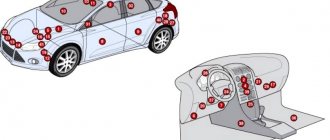
On all cars of the Tenth Family, the power lines for the lights contain many elements. There are lamp health relays, switches and fuses. Therefore, if the brake lights on a VAZ-2112 do not light up, you need to check the entire chain. But the reason may look simple: sometimes the lamps do not turn on because the socket does not contact ground. Circuits are easy to analyze, but finding the cause of a breakdown is difficult. Let's look into the details.
If one of the lamps does not light, it is simply replaced. See the example in the video - you need a P21 W
» data-lazy-type=»iframe» src=»data:image/gif;base64,R0lGODlhAQABAIAAAAAAAP///yH5BAEAAAAALAAAAAABAAEAAAIBRAA7″>
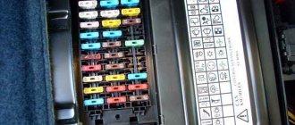
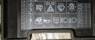
Fuse layout diagram for VAZ 2110, 2111, 2112
The photo shows fuses for VAZ 2110, 2111, 2112
As you can see, each fuse is numbered with a corresponding index.
In the above illustration, the unit is located on the left side of the steering column and is integrated into the instrument panel. Below are the values of the specific fuse in this mounting block. Table of fuse values for VAZ 2110, 2111, 2112.
| Fuse, no. | Current strength, Ampere | Values |
| F1 | 5 | Lamps for illuminating registration numbers, luggage compartment space, the entire left side of the vehicle's side lighting, as well as instrument lighting for dimensions and instruments. |
| F2 | 7,5 | Low beam left headlight |
| F3 | 10 | Left high beam |
| F4 | 10 | Front right fog lamp |
| F5 | 30 | Electric windows in doors |
| F6 | 15 | Cigarette lighter/lamp portable |
| F7 | 20 | Horn, engine radiator fan |
| F8 | 20 | Heated rear window |
| F9 | 20 | Windshield washer and wiper |
| F10 | 20 | Spare |
| F11 | 5 | Side light on the right side of the car |
| F12 | 7,5 | Low beam right headlight |
| F13 | 10 | High beam right headlight |
| F14 | 10 | Front left fog lamp |
| F15 | 20 | Heated seats |
| F16 | 10 | Left and right turn signals, hazard turn signals |
| F17 | 7,5 | Interior light, ignition switch illumination, brake lights, clock and computer illumination |
| F18 | 25 | Illumination of the glove compartment, heating controls, cigarette lighter |
| F19 | 10 | Reversing lamps, indication of instruments, computer, clock, serviceability of brake lights, door locking |
| F20 | 7,5 | Rear fog lights |
First test drive of Lada Vesta
For clarity, the principle of parallel arrangement of some fuses is clear: F1-F3 are responsible for the electrics on the left side of the car, and those located opposite F11-F13 are responsible for the right side of the car. The rest are responsible for other vehicle functions.
This is interesting: How to determine that the strut support bearing is knocking
Reasons why the reverse lamps do not light up
It is not difficult to see that when the reverse light on a VAZ2110 does not light up, the reasons can be of a very different nature. But be that as it may, everything needs to be corrected, and for this the cause must be eliminated.
To do this you need to do the following:
- It is necessary to determine the condition of fuse No. 19. It is designed for a power of 7.5 A. Its location is the rear light board of the VAZ 2110 mounting block under the dashboard.
- Next you need to make sure that the light bulbs are working properly. If it turns out that there are no problems with them, you need to check the reverse sensor.
In the latter case, the question of its location may arise. When viewing the car from the front, it is on the right side. If we consider it in projection in the direction of travel, then it will be located in the gearbox, in its lower left part.
Car enthusiasts gave this sensor its name, calling it a frog. It is nothing more than a regular switch. The gearbox has a hole where this sensor is placed. Its working surface looks inside the box. From the outside, in the normal position, the contacts are open. When reverse gear is engaged, a special shield presses on the working surface of the sensor, which leads to the closure of the contacts. This provides power to the reversing lights. The sensor differs from a conventional switch in its special design. The device is sealed and resistant to significant mechanical loads.
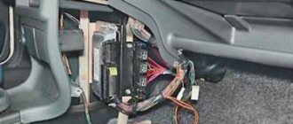
Main unit
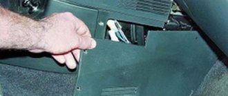
The main block with fuses and relays is located in the cabin, on the left side, under the control panel. To access, press the latch switch.
Photo - diagram Option 1
Scheme Option 2
Scheme Option 3
Description of fuses
| F1 | 5A Lamps for license plate lights. Instrument lighting lamps. Side light indicator lamp. Trunk light. Left side marker lamps |
| F2 | 7.5A Left headlight (low beam) |
| F3 | 10A Left headlight (high beam) |
| F4 | 10A Right fog lamp |
| F5 | 30A Electric motors for glass door lifts |
| F6 | 15A Portable lamp |
| F7 | 20A Electric motor of the engine cooling system fan. Sound signal |
| F8 | 20A Rear window heating element. Relay (contacts) for turning on the heated rear window |
| F9 | 20A Recirculation valve. Windshield, rear window and headlight cleaners and washers. Relay (coil) for turning on the rear window heating |
| F10 | 20A Reserve |
| F11 | 5A Starboard side marker lamps |
| F12 | 7.5A Right headlight (low beam) |
| F13 | 10A Right headlight (high beam). High beam warning lamp |
| F14 | 10A Left fog lamp |
| F15 | 20A Electric seat heating. Trunk lock lock |
| F16 | 10A Relay - turn signal and hazard warning light switch (in hazard warning mode). Hazard warning lamp |
| F17 | 7.5A Interior lighting lamp. Individual backlight lamp. Ignition switch illumination lamp. Stop lamps. Clock (or trip computer) |
| F18 | 25A Glove box lighting lamp. Heater controller. Cigarette lighter. |
| F19 | 10A Door locking. Relay for monitoring the health of brake light lamps and side lights. Direction indicators with warning lamps. Reversing lamps. Generator excitation winding. On-board control system display unit. Instrument cluster. Clock (or trip computer) |
| F20 | 7.5A Rear fog lamps |
Fuse number 18 at 25A is responsible for the operation of the cigarette lighter.
The fog lamp fuse is installed separately in the instrument panel niche behind the main unit.
Relay purpose
- K1 - lamp health monitoring relay
- K2 - windshield wiper relay
- KZ - relay-breaker for direction indicators and hazard warning lights
- K4 - relay for low beam headlights
- K5 - headlight high beam relay
- K6 - additional relay
- K7 - rear window heating relay
- K8 - rear fog lamp relay
Electrical diagram of the block
Connection diagram
Troubleshooting methods
What are the troubleshooting options:
- If there is no backlight, you need to check the fuse and replace it if it is blown. All failed light bulbs must be replaced.
- If the sensors are not working, you should check the integrity of the wiring with a multimeter or other tester to check the wiring. Damaged sections of wires also need to be replaced.
- If the car interior is humid, over time this can lead to oxidation of the shield contacts. If such a malfunction occurs, the contacts must be cleaned or replaced.
- If the problem lies precisely in the inoperability of the instrument cluster, then it is better to entrust the repair to specialists. It is possible that in the process you will have to resolder some elements, so if you do not have experience in carrying out such events, then contact an electrician (the video was shot by Alexey Lipatov).
Instructions for dismantling the tidy
So, how to remove and disassemble the device for its subsequent repair or replacement:
To begin, you will need to use a Phillips screwdriver to unscrew the two self-tapping screws located on the top trim. After this, you also need to unscrew two more bolts, they are located on the bottom of the lining. Then you need to carefully detach the cover and put it aside. Next, the connectors with wiring from the buttons located on the sides of the device are disconnected. This will allow you to move the trim to the side. Only after these steps can you unscrew the two bolts that secure the tidy to the center console
They are located at the ends. Then you need to carefully slide the combination back, parallel to disconnecting it from the metal plates installed on top. For complete dismantling, you also need to disconnect the two connectors with the wiring on the back of the panel. Having done this, you can remove the device from the mounting location and begin repairing or replacing it. The assembly procedure is carried out in reverse order.
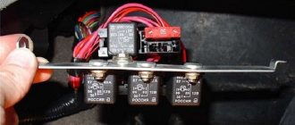
Location of additional fuses and relays
In the figure below we see how to get to the additional fuses of the car. Located to the right of the central panel, the screws are twisted and the cover is easily removed.
Removing the cover for diagnostics and replacement of additional fuses and relays
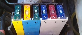
Below we see the fuses themselves, there are 6 of them, 15 Amps each.
Location of additional fuses
- Ignition controller,
- Sensors for oxygen, air flow, speed calculation,
- Fuel pump and relay, injectors,
- Fan,
- Gasoline pump,
- Ignition.
We remind you that F1-F20 are so-called fuses. This means that jumpers and other “tricks” are not acceptable when working. If you replace such a fuse with a jumper yourself, you risk system failure.
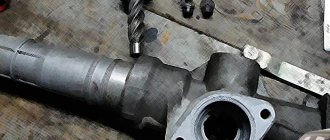
Algorithm of actions when replacing a sensor
Changing it is not particularly difficult, but you need to do the following:
- To replace the car, you need to put it in a pit or drive it onto an overpass.
- If there is engine protection, it must be removed.
- You should first prepare some kind of container for the oil, since the moment the sensor is unscrewed, a certain part of the oil will leak out.
- Then you need to unscrew the wires that are connected to the sensor.
- The old sensor must be removed and a new device installed in its place.
- The oil that leaked out during the sensor replacement process must be added to the box.
- Next, the wires are connected. They must first be wiped dry to remove any oil that has got on them.
- Then you should start the car and check for light from the bulbs when reverse is engaged.
Such measures are one of the options for eliminating the problem in which the reverse lights of the VAZ 2110 do not light up.
Additional block
It is located under the center console and is covered with a lid. One part is accessible from the right side.
Scheme
Designation
- 15A - Ignition module, controller
- 15A - Canister purge valve, vehicle speed sensor, oxygen concentration sensor (heating), air flow sensor
- 15A - fuel pump, fuel pump fuse, injectors
- Electric fan relay
- Fuel pump relay
- Main relay (ignition relay)
The other part is on the left side of the console:
Scheme
Decoding
- Central locking control unit
- Immobilizer block
- Relay for turning on rear fog lights.
Installation process
Ready-made kits usually contain an installation diagram for the VAZ 2110. However, you should understand that adjustments may need to be made during the process.
Before starting installation work, you need to make sure there is space for them. If it is not provided for in your model, then you should think about it and decide on it yourself. It is recommended to do this through the front bumper.
The installation procedure is as follows:
- At the very beginning we lay out the wiring for the fog lights. It is laid in the same way as the main wiring - along the wing, through the left side (under the hood).
- After this, you need to supply power to the button, which will need to be placed on the dashboard. According to the standard, power is supplied from the fuse on the right dimensions. However, you can go the other way by connecting power to the light switch. You can take power from the output to the dimensions, but this method should be used last, since the battery may discharge prematurely if you forget to turn off the PTF.
- We connect the plug together with the headlights. If the lights do not light up, then there was some error in the circuit. Each component of the network should be carefully checked. Often the problem is in the relay. To identify it, you need to make sure there is a click; if there is none, the relay should be completely changed.
It is quite simple to check that the headlights are set correctly and are working correctly: drive out onto the road and turn on the headlights.
If the light is directed slightly downward, but illuminates both the road surface and the side of the road equally well, everything is installed correctly.
Signs of faulty fuses
- The module has changed color, black dots are visible on the surface, carbon deposits,
- On the instrument panel (European panel) an indicator indicates a malfunction in the engine compartment,
- When the engine is running, the ignition is on, the battery is charged, some mechanisms do not work, they do not work correctly,
- In the car interior you can hear the smell of burning, melted in the area where the mounting block is located,
- The modules feel hot to the touch.
This is interesting: What kind of drilling for a Volkswagen Polo
Checking the functionality of the sensor (frog)
When you manage to find it, you need to check its performance status:
- The wires connected to it must be disconnected.
- A tester is connected to their ends. The device is switched to “resistance” mode and the measurement is carried out.
- Then reverse gear is engaged.
- The ignition is switched to the on state.
- The instrument readings are taken.
The device may show 0 Ohm. This means that there are no problems with it. If there are other indicators, it needs to be replaced. This must be done not only when the VAZ 2110 does not have reverse gear on, but also when the lights are on and reverse gear is not engaged.
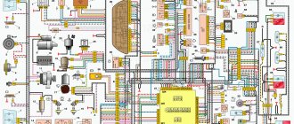
Standard version of the brake light operating diagram
Power is supplied to fuse F17 from the battery, then the current goes to limit switch contact 11, and then, if the limit switch is closed, a circuit is formed with the filament of lamps 7. But note: part of the circuit is relay K1, more precisely, its contacts 5 and 4.
Basic network diagram
A complete electrical diagram with explanations of the VAZ-2112 car is here.
If the brake lights do not light up, on the VAZ-2112, as on all Tens, check one fuse. It is called F17 and is located in the mounting block to the left of the driver.
Main mounting block
It is important to know: voltage is always present at one of the fuse terminals. Check it out!
A few words about the “serviceability relay”
The lamp health relay is called K1, and it is the largest in the mounting block. If you remove this relay, then when you press the pedal you can dial the voltage at terminal 5 (but not 4). Look at the diagram again, and it will become clear what we are talking about.
The largest relay in the block
All relay contacts are numbered. Check the voltage at the block terminals:
- 6 – “mass” potential;
- 2 – voltage “+12”, but only after turning on the ignition;
- 5 – “+12” by pressing the pedal;
- 4 – the terminal rings like a ground tap.
If the potential “0” is not generated at terminal “4,” it means that the lamp filaments are burnt out or there is a break in the wiring. Now consider something else: the ground potential has been detected, but the lamps do not light. This is where suspicions of a short circuit arise.
How to change?
- Place the VAZ 2110 in a pit or drive it on an overpass.
- Remove the engine protection, if any.
- Have a small container for the oil. Because when you open the sensor, oil will begin to flow out.
- Get under the car and disconnect the wires going to the part.
- Open the old sensor, immediately insert the container and screw in the new one.
- Add the leaked oil into the box.
- Stick in the wires, wipe the surfaces on which oil has gotten.
- Start the car and check if the lights come on when you put the vehicle in reverse.
For reference: A new one is inexpensive - from 100 rubles. Usually at the factory they install them from the VAZ 2108.
Reasons for premature failure of fuses
- A natural factor is the duration of operation without intermediate prevention,
- Moisture ingress, condensation formation, terminal oxidation, insulating layer drying out, electrical supply circuit breakage,
- Mechanical damage, accident, shock, collision,
- Damage to the car fender, windshield, which contributed to damage to the mounting block,
- Short circuit in the electrical supply circuit,
- Exposure to ultraviolet rays.
If after replacing the modules the equipment does not work, then the power supply circuit line is most likely damaged. In the worst case scenario, part failure. Carefully inspect the wiring sections from the battery, generator, starter to the relay switch.
The operating instructions for the technical means indicate the interval before replacing the modules of the mounting block is 40,000 km. In practice, the resource is 5 – 7 thousand km longer.
To prevent premature wear of modules, systematically check the condition of the wiring insulation, the quality of fixation of the terminals, and remove oxidation with fine sandpaper.
As consumables, purchase original domestically produced parts. Check the catalog numbers with the data specified in the instruction manual. Imported analogues are comparable in quality to the Russian manufacturer, but the price is twice as expensive
What else to pay attention to
Very often, the appearance of such malfunctions occurs due to the fault of the rear lights, or more precisely, in the places where the connectors with wires and lamp sockets are connected. Using a measuring device or a test lamp, check the presence of power at the rear light connectors with the brake pedal pressed or the wires on the switch connected to each other. If it is missing, you should carefully check the condition of the wiring harness.
Oxidation of contacts in connectors or sockets of electric lamps can be removed using available means. It is not advisable to use sandpaper for this, even very fine sandpaper. Alcohol-containing liquids are best suited for this, as they remove the resulting oxidation.
Circuits protected by additional fuses (all fuses on A) on the VAZ-2110:
Additional fuses: 1 – ignition module, controller; 2 – canister purge valve, vehicle speed sensor, oxygen (heating) sensor, air flow sensor; 3 – fuel pump relay, fuel pump, injectors.
Additional relays: 4 – electric fan relay; 5 – electric fuel pump relay; 6 – main relay (ignition relay).
There is a fog lamp fuse installed in the niche of the instrument panel behind the mounting block:
PRICES OF COMPONENTS
There is also a separate section for prices for all the parts that may be needed when repairing this part of the car, because if the side lights on a VAZ 2114 or the fuses have blown, they will still have to be replaced with new ones. In any case, all the components are quite cheap, all we might need:
- Marker lamp;
- Fuse;
- Power button;
- A whole fuse block.
Today, an ordinary white light bulb costs up to 30 rubles; of course, the price depends on the individual pricing policy of a particular seller. Individual fuses can be selected for up to 50 rubles, unless, of course, you want to install a higher quality option. Button, if you look for exactly the same one as the original one, you will have to pay up to 300 rubles. In some situations, more serious problems may arise and you will have to change the entire unit, this is quite an expensive proposition, together with all the wires it will cost up to 1000 rubles.
Article 2: How to correctly replace the fine fuel filter on a VAZ 2114
VAZ 2114 (2113) stops do not work
The VAZ 2114 (2113) car is equipped with brake lights in the rear lights (one in each light).
Plus, an additional brake light in the spoiler on the rear door. There are few reasons why the brake lights of a VAZ 2114, 2113 car do not work. Let's list them all and try to figure out this problem ourselves.
Stop lights (brake lights) of VAZ 2114 (2113) do not work, reasons
Either one brake light or two at once may not work.
The brake light bulb in the rear light is burnt out.
Most often, only one lamp burns out, but sometimes two lamps burn out.
Brake light (stop) lamp in the rear light of a VAZ 2114 (2113) car
In this case, you will have to replace the lamp with a new one or a known good one. The brake light uses a P21W lamp. Similar lamps for the turn signal, reverse light, and fog light are in the same rear light. They can be used to check the brake light by replacing it.
The contacts in the stop lamp socket have oxidized
In this case, a “break” occurs in the electrical circuit of the lamp. Most often, in this case, one brake light will not work, while the other will be on.
How to and how not to check the “0 Volt” potential
Let’s agree right away that we only work with a voltmeter. Voltage “+12” is caused by connecting one probe to ground. The presence of potential “zero” is checked differently: any of the probes is connected to a terminal with positive voltage, and then the second probe is connected to the wire being tested.
Consider the error: one probe is connected to ground, the second to the terminal being tested, and vol. Here they conclude that there is a “mass” potential, but this is wrong! If the contact with ground is broken, the device will also show “0”. That is, the number “0” does not contain information.
Common problems with brake lights
There may be several reasons:
- blown fuse;
- faulty sensor;
- frayed or broken power cord.
The most common cause is a blown fuse responsible for protecting the signal light circuit. This fuse is located on a block built to the left of the steering column. This capacitor can withstand a current of 7.5 amperes, as evidenced by the inscription on it. It is located in the bottom row, fourth from the right edge.
If after replacing this circuit element the problem has not been resolved, other possible causes of failure should be considered.
The next troubleshooting point is to check the brake light sensor. To do this, you need to check whether voltage is entering and exiting the sensor. In this case, you need to use a control lamp. If the lamp does not light up when connected in front of the sensor, then the problem may be in the wires going to the sensor. If the lamp works before the sensor, but not after, then the problem lies in this part. You can also simply disconnect the input and output of the sensor and close it “directly” using a copper wire; if after these manipulations the lights in the brake lights light up, then the reason is precisely in the sensor. The sensor cannot be repaired, and the only way out is to replace this part with a new one.
Damaged wires may also be the cause, this will be especially noticeable if the just replaced fuse blows out - this means that the wire is frayed and there is a contact to ground. If the fuse blows without pressing the brake pedal, the wire before the sensor is damaged, and if it blows after pressing, the wire after the sensor is damaged. If there is no voltage, perhaps the wire is simply broken and does not short to ground. When troubleshooting, you should pay special attention to bends and possible areas of damage to the wires.
The next cause of problems is burnt-out LEDs in the brake light; there have been cases when both burned out at once. To replace the light bulbs, you need to remove the flashlight board by squeezing it from the sides and pulling it slightly towards you. Next, you should visually inspect the light bulbs; perhaps a visual inspection will already answer the question about the reason for the non-working brake light. After this, you should replace the old lamps with new ones.
The problem of many VAZ 2112.11 owners is to achieve trouble-free operation of these unfortunate lamps, we will fix it!
for this we need:
-control lamp with power supply
1)
Check the light bulbs and fuse F17. If they are whole, go to point 2. Otherwise, replace and look. Are they glowing? Great! No? Let's move on to point 2.
2)
The “twins” have one problem - the wiring harness going to the trunk door. It is usually located in the right corrugation (in the left wire to the rear wiper, I believe there is the same problem, but I got the car without a wiper). Checking this area is quite simple. You will need a multi tester or a 12 volt power supply (preferably both)
Behind the “skin”, on the right, where the rear right headlight with “turn signal” and “fog light” runs a wire along the iron, you can feel it without removing the fabric. This wire has a male-female connector. Let's disconnect it. “Dad” goes to the lights, and “Mom” is the signal coming back from the mounting block.
First of all, we check for short circuit (preferably with a multi tester) the male connector. There are four contacts “black - minus; red-stop including extra in spoiler; green – reverse; white – trunk opening solenoid. Next, we check each wire for breaks. Again, using a multi tester, one contact to the wire on the male connector, the other to the corresponding wire in the headlight block (black-black, red-red, etc. one by one, check the short circuit with other wires). If everything is in order, then using a 12V power source you can light the lamps. If they don’t light up, the reason is most likely in the circuit boards of the headlight itself, a lot has been written about this (by the way, the spoiler stop still lights up another connection there). If you get tanned, go to step 3. Connect the connector back.
Otherwise, we eliminate the short circuit, most likely it is in the very place where the wires go to the door, you will have to remove the trim, the side trim on the roof pillar, one ceiling cap - the far right one, the trim on the trunk door itself, and pull out the harness until the inspection point appears. Be careful with the rear window heating wire; it will need to be returned! I hooked another wire to this wire and only after that I began to pull it out, returning the harness to its place, pull it by the wire and pull the contact back. I had a break in the “minus” and a short circuit in almost all the wires. He healed and returned the tourniquet to its place; if desired, it can be replaced with a new one (it was in the evening, there was nothing to ride on!). We return the wires, not forgetting to connect the connector. Let's check. Are they glowing? Great! No? Let's move on to point 3.
3)
We check the fastening of the black wire of the “mother” to the body - when checked with a multi tester, it should produce a short circuit to the body. The mounting location itself is located in the left niche of the luggage compartment. If everything is in order, read on (otherwise, of course, we will find out the cause and check; in the absence of a “minus”, the reversing lights, solenoid and stop lights will not work, most likely the wiper will not work either). Next we move to the driver's seat. There is a “frog” above the brake pedal. Two wires come to it, one always has 12V “+” (in my opinion it’s white with a red stripe), we check this fact with a tester on the case. Is there tension? Yes! Let's move on to point 4. No, read on...
If there is no voltage on any wire, “it’s rubbish” - a ground break - unlikely, but possible. I can't imagine where it could happen. Purely theoretically, the mass can be taken anywhere. Once the car starts, and only the rear brake lights do not light up, it means there is a mass somewhere close. However, a broken ground wire in a car is a huge source of danger, it must be found... We eliminate the source of the problem. Let's check. Are they glowing? Great! No? Let's move on to point 4.
4)
There is voltage on the wires! We check the “frog” itself; the multi tester (on the contacts of the “frog”) should show a short circuit when the brake pedal is pressed. No ? We change the frog (by the way, you can short-circuit the two wires coming to the “frog”, the brake lights should light up). Let's check. Are they glowing? Great! No? Let's move on to point 5.
5)
There is one weak link left... Relay for checking the integrity of lamps or as it is called Relay BSK. Most likely, the spiral there burned out, I suppose you can solder another one, but the cost is not high, so I replaced it completely. Let's check. Are they glowing? Great! No? Let's move on to point 6.
6)
Here I can assume a break in the lead in the cable to the distribution block. It’s not a pleasant task; you’ll have to open the upholstery and look for it. Or throw a makeshift directly from the “frog” to the connector that we found in point 2
The VAZ-2112 passenger car can be equipped with three brake lights, two of which are located in the right and left rear lights, and the third, which is additional, is on the spoiler. You cannot drive onto the road with brake lights that are not working, because they are the ones who warn drivers behind moving vehicles about your braking, which allows you to avoid a rear-end collision with your car.
There are two options for the brake lights not working, either the light in one of them does not light up, or all the lights in these lights do not light up. In the first case, the driver will have to check the condition of the brake light lamp to see if its tungsten filament has burned out. If the filament burns out, then replace it with a new light bulb of similar power. And if the light bulb is intact, then we clean the contacts in its socket and slightly pull out the central contact.
In the second case, it will take much longer to find the fault, since the likelihood of all three lamps burning out at the same time is unlikely. First, we check the condition of the fuse that protects this electrical circuit. This can be done very quickly, just turn on the interior lighting. If there is light, then fuse F17 (7.5A) is safe and sound, since it also protects this electrical circuit, and if there is no light, then you will have to open the mounting block and make sure that the fuse has blown.
Considering that the brake lights are located in the rear door, this means that the wiring harness going to them will bend if this door is opened or closed, which over time can lead to wire breaks. To check this assumption, you need to find the connector, which is located on the right behind the interior trim. You will have to disconnect it and use a tester to check the connector, which is popularly called “male,” for a short circuit. You will be interested in two wires: red (+ for brake lights) and black, it goes to ground.
If there is no tester, then you can check the condition of these two wires in another way. To do this, you will need two long wires to connect the positive terminal of the battery to the connector contact where the red wire goes, and the negative terminal of the battery to the contact with the black wire. If it turns out that the brake light lamps do not light up, then you will have to dismantle this wiring harness and then fix the problem. Well, if it turns out that the brake light lamps are on, then you will have to use a tester to check the wires of this female connector to the mounting block block. Also, a possible malfunction may be the brake light switch located above the brake pedal.
One answer
All stoplights stopped working at once, it turned out that the problem was in the lamp serviceability relay (price 145 rubles)
Popular posts:
The last notes:
Each of us faces problems while operating a car. It's always unpleasant. However, sometimes these problems can be solved on your own.
The main goal of this site is to help motorists avoid unnecessary costs when repairing cars by suggesting the causes of the malfunction and options for eliminating it.
We are focused on live communication, so we look forward to your comments and mutual assistance to other motorists.
Thank you for being with us and good luck on the roads!
If you found your photo or text on our resource, tell us about it. We will indicate your authorship or remove the material.