Some car owners ask search engines where the VAZ 2114 starter fuse is located, but they do not find an answer, because the VAZ 2114 and earlier models of cars from this manufacturer do not have a starter fuse. On several sites, in response to requests for the location of the fuse, huge reviews have been written about the mounting block, but they also do not essentially answer the question posed, because there is no fuse in the mounting block .
The protective function is assigned to the auxiliary relay - a compact device that is located under the steering wheel next to the hood release handle.
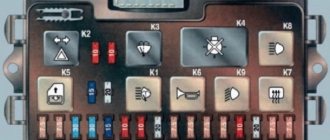
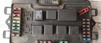
Mounting fuse block VAZ 2114
In cars like VAZ 2114 there are two fuse blocks - main and auxiliary. The first is located near the motor and contains fuses responsible for protecting the main equipment. The second part is hidden in the cabin and plays an auxiliary role.
Main unit
To access the panel, unclip the cover and remove it. The fuse links and relays will open inside.
The main control elements of power circuits and equipment are concentrated here.
Additional block
To open the additional block you will need to use a screwdriver. The panel is located at the front passenger's feet and is covered with a plastic cover. The protection is held on by 4 screws, and you need to unscrew them. Next, the user has access to the protection elements of the auxiliary circuits.
VAZ 2114: fuse and relay diagram
On the fourteenth model with an 8-valve engine, two power supplies are installed. The first is located inside the engine compartment. More specifically, the block is located under the windshield on the right side in the direction of travel of the car. Externally, the device looks like a black box with a plastic lid.
The indoor unit is located in the cabin, under the feet of the front passenger on the left. The side part of the instrument panel is made in the form of an inspection hatch that provides access to the protective elements.
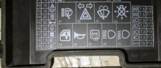
Connection diagram for mounting block 2114
The figure schematically shows the terminals and wiring connections of the main mounting block. The double index indicates the number of the pad and plug.
Pinout of mounting block connectors
The fuse mounting block has several terminals for connecting on-board wiring.
The following is the pinout of terminal block Ш1:
- 1 – window regulator;
- 2/3/5, 6/8 – ignition system;
- 4 – electric motor of the stove.
Ш2
- 1 – aft windshield wiper;
- 2/15 – turn signal activation buttons for left and right, respectively;
- 3 – ignition system relay;
- 4 – checking the serviceability of the lighting lamps;
- 5 – emergency warning button;
- 6 – front left door;
- 7/9/16 – reserve system output;
- 8/11/12/14 – dump controls for high beams, dimensions, handbrake displayed on the dashboard;
- 10 – rear fog light switch;
- 13 – illumination of the interior of the car;
- 17 – body weight.
Ш3
- 1 – speedometer connection line;
- 2 – emergency warning button;
- 3 – turns;
- 4 – lubricant level diode in the engine crankcase;
- 5 – mass;
- 6 – antifreeze level in the expansion tank;
- 7 – ABS control;
- 8 – switch for head optics and backlight;
- 9 /11/12/18-20 – washer control button;
- 10 – connection of a portable light bulb;
- 13 – adjustment of external lighting;
- 14 – control of dimensions;
- 15/17/21 – reserve outputs;
- 16 – oil pressure gauge.
Ш4
- 1 – monitoring and control of the stern window heating mechanism;
- 2/12 – switches between low and high beam;
- 3/8 – tidy;
- 4 – key for turning on external optics;
- 5 – tidy rheostat;
- 6/11/14 – spare terminals for connecting auxiliary equipment;
- 7 – windshield cleaning device regulator;
- 9/10 – keys for turning on the dimensions and horn, respectively;
- 13 – block of steering column switches;
- 15 – head optics wipers;
- 16-18/20 – controls for brake fluid and antifreeze levels and battery charging;
- 19 – fog light button;
- 21 – connection of an electronic tachometer.
Ш5
- 1/2/3/6 – buttons for switching on the low and high beam;
- 4 – starter;
- 5 – drive of the head radiator fan.
Ш6
- 1/4-6 – reserve contacts;
- 2/12 – reverse button;
- 3/11 – connection of the turn signals of the front of the car;
- 7 – wiper switch;
- 8/10 – dimensions;
- 9 – switch for engine compartment lamp;
- 13 – sensor in the brake expansion tank.
Ш7
- 1/4 – reserve inserts;
- 2/3 – front optics cleaner motor;
- 5 – DUM;
- 6 – horn;
- 7 – speedometer;
- 8 – DTOZH;
- 9 – generator output;
- 10/14 – BUEM;
- 11 – engine compartment lamp sensor;
- 12 – expansion tank sensor;
- 13 – ABS sensor;
- 15 – power supply to the ignition coil;
- 16 – DUOZH;
- 17 – fog light relay.
Ш8
- 1 – fog light relay;
- 2/3 – front fog lights;
- 4 – ignition coil;
- 5/6 – generator output;
- 7/8 – starter and foglight relays.
Ш9
- 1 – reserve;
- 2/9 – turn signals for the rear of the car;
- 3/18 – rear wiper motor;
- 4 – power supply for fog lights;
- 5 – tailgate door end switch;
- 6 – similar element of the front right side;
- 7/13 – “chandelier” in the salon;
- 8 – button indicating that the handbrake is turned on;
- 10/19 – heated rear window;
- 11 – number plate illumination;
- 12 – front left door;
- 14 – feet;
- 15/17 – dimensions;
- 19 – heated rear window.
Interpretation of fuses and relays of injection models
Injection-type models use a different mounting block design. Consequently, the arrangement of elements and fuse links may differ.
For example, we take a diagram of a mounting block type 3722010-60
| Item number | Area of responsibility |
| F1 | Aft fog lights |
| F2 | Hazard alarm and turn signals device |
| F3 | Lighting devices and control lamps |
| F4 | Heated rear window and terminal for connecting a portable lamp |
| F5 | Radiator Fan Fuse |
| F6 | Window lifters |
| F7 | Heater motor, cigarette lighter, heated rear window |
| F8/9 | Front fog light switches |
| F10 | Illumination of the instrument panel and indication of warning lamps, left side of the dimensions |
| F11 | Right side side lights |
| F12/13 | Low beam headlights |
| F14/15 | Long range lighting |
| F16 | Turn signals and their breaker |
| F17-20 | Reserve sockets |
Separately, you should consider the protective inserts of the fuse box.
| Number in the diagram | Purpose |
| K1 | Wiper drive |
| K2 | Turns and emergency lights |
| K3 | Lobovukha cleaner |
| K4 | Control of dimensions and turn signals |
| K5 | Power windows throughout the car |
| K6 | Klaxon |
| K7 | Heated stern window |
| K8/9 | Long and short range operation of head optics |
Decoding fuses and relays of block 2114-3722010-18
Older injection-type models are equipped with different fuse blocks. Here the location of the fuse links is as follows:
- F9/8 – fog lights;
- F1/7 – head optics cleaners, their contacts and valves, glove compartment lighting, equipment warning lamps;
- F16 – turn signals, hazard warning switch, oil pressure, TPS and handbrake indicator lamps;
- F3 – interior lighting, reversing lamp;
- F10 – fuse for rear license plate illumination, engine compartment lighting, dimensions control, cigarette lighter illumination, heater buttons, left side of dimensions;
- F11 – right side of dimensions;
- F2 – control of emergency gang operation;
- F4 – power fuse protecting the heated stern glass, portable socket;
- F15 – high beam head optics;
- F14 – light switching controller and corresponding lamp;
- F13/12 – right and left low beam.
Additionally, there is a decoding of the protective relays
- K1 – protective insert for headlight washers;
- K2 – emergency lights and turns;
- K3 – windshield wipers;
- K4 – indication of warning lamps;
- K5 – activation and operation of power windows;
- K6 – horn circuit;
- K7 – heated rear window;
- K8/9 – low and high beam headlights.
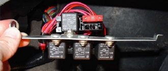
Explanation of the additional fuse and relay block
The auxiliary block does not have a large number of protective inserts. There are only three relays and fuses here:
- 1 – main distributor relay;
- 2 – controller power supply;
- 3 – pump protection.
There is also an equal number of control inserts:
- K4 – fuel pump;
- K5 – head radiator fan;
- K6 – main relay of the controller.
Operating principle, design and characteristics of fuses
The principle of operation of fuse links is deciphered by their name. Fuses are made of low-fusible conductors that can withstand a certain amperage. Depending on the purpose and voltage of the circuit being served, fuses are divided according to the current strength they can withstand. Typically, VAZ 2114 uses inserts from 5 to 30 Amperes.
Purpose of fuses
The main purpose of the fuse is to protect devices and equipment from overloads and short circuits. If the maximum limit is exceeded (short circuit inside the wiring circuit), the part is destroyed, which leads to an open line. Consequently, the part remains undamaged.
Common faults
Among the frequent calls to the service station are:
- wiring burnout;
- water entering the contacts and, as a result, closing them;
- damage to wires;
- malfunctions of electronic units.
With rare exceptions, the fuse box itself breaks down.
Checking and replacing fuses and block
To check the fuse for serviceability, remove it from the socket and visually inspect it. If the part is intact, there will be no soot or traces of oxidation on it. Direct replacement is carried out using the pliers included in the kit. It is strictly forbidden to pull out the inserts by loosening them - you can break the legs.
Repairing the block is getting more complicated. Here you will need to perform the following sequence of actions:
- open the mounting panel cover;
- find and unscrew the 4 mounting screws;
- Carefully lift the module and disconnect the terminal blocks.
It is important to exercise extreme caution when performing the procedure - the part can be easily damaged.
The most common breakdowns
One of the most common problems is the loosening of the power cable tip. Simply tighten it and check all the other nuts at the same time. The second popular reason for the failure of this unit is considered to be oxidation of contacts. If you notice a problem at an early stage, then just clean the contacts and the unit will work properly. If cleaning doesn't help, you will need to replace them.
Oxide often occurs on the winding, making it impossible to block. You can try to clean the winding, but experienced motorists recommend replacing the relay immediately, this way you will be able to drive your car much longer without problems.
Another probable cause of problems with starting the engine is a break in the retractor power supply circuit. You will have to find them and fix the problem. Find the broken wires and place new ones in their place. Upon completion of work, check the relay power circuit again. One way to check the functionality of a disassembled relay is to check it with an ohmmeter. To do this, you need to place the probes of the device on the turns of two windings.
Sometimes it is enough to replace the anchor. This must be done when it operates slowly or is idle. These signs directly indicate a malfunction of the anchor itself. It will be quite difficult for a car enthusiast with little experience to identify problems with this element.
Repairing a relay is more expensive than replacing it, so the easiest way is to immediately replace the faulty part. This will save your time, because it is unknown whether repairs, which are often very labor-intensive, will help. An attempt to restore the unit is fraught with danger - if the relay is repaired incorrectly, you can be left without a car for a long time, since engine starting will be blocked. In this case, you will need to carry out more complex repairs, which cannot be carried out without the participation of specialists.
Rear fog lamp relay
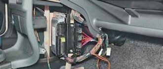
In order for the user to quickly and easily diagnose the operation of mechanisms and devices, the designers placed the rear fog light relays separately from the main units.
The element is located under the dashboard, where the hood opening hook is installed. The starter control module is also mounted here.
Location of the VAZ 2114 starter relay
Starter protection is designed to protect the circuit of the corresponding unit from overload or short circuit. In appearance, it is a standard four-pin device suspended on a bolt inside the engine compartment.
In this case, the injector or carburetor is designed in the same way - the block is suspended independently. The exact location of the element is impossible to describe. Thanks to the “special” approach of the designers, the hitch may differ depending on the year of manufacture. Therefore, it is best to start your search from the starter terminals and move along the wires to the device itself.
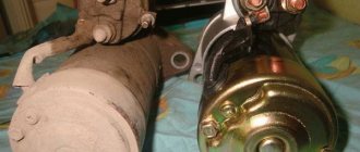
Locating the starter relay
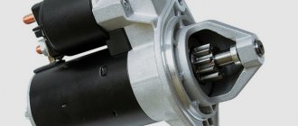
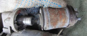
The starter retractor is an electromechanical device installed directly inside the unit housing.
The part is responsible for the clutch of the engine flywheel with the electric motor gear. The search is carried out by visual inspection. The retractor is located in the same housing as the main unit and has two large contacts coming from the ignition switch and the battery.
Retractor design
The VAZ 2114 starter solenoid relay is located on the housing of the starting electric motor and is securely fastened to it. The device consists of separate windings and a contact group.
Mechanism of action
Operating principle of the device:
- when turning the ignition key, power is supplied to the retractor winding;
- the working plate, under the influence of current, is pressed against the contacts;
- power is supplied to the starter;
- the engine turns over and the engine starts.
Signs of malfunction of the retractor relay on the VAZ 2114
There are a number of symptoms that indicate a device failure. The symptoms are specific to this part and are difficult to confuse with other problems.
Typically, masters highlight:
- nothing happens after turning the ignition key;
- the starter fires, but does not turn off, which is accompanied by a characteristic sound.
No clicking of the solenoid relay
If there is no characteristic sound of the solenoid relay operating, the problem should be looked for further:
- the contacts of the working plate have oxidized;
- there is damage to the ground cable;
- The solenoid coil of the relay is burnt out.
There is a click, but the starter does not turn
If after turning the key there is a characteristic sound, but then nothing happens, the components are checked.
- Charging the battery. If there is no voltage on the windings, clicks may appear, but the current will not be enough to start the motor.
- Damage or wear to the commutator.
- Oxidation of the retractor element.
The relay is activated, the starter starts the engine, but does not turn off
The most common cause is a clogged starter armature. In this case, the bendix wedges and its working part does not disengage. In second place is a breakdown of the ignition cylinder - the key release may not work, or the contact group does not move easily enough.
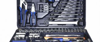
Instructions for replacing the relay on a VAZ-2114
Replacing the starter solenoid relay, as well as the engine itself, is a responsible process that requires close attention and extreme care.
Starter relay installation diagram
The electrical circuit for connecting the starter relay is not complicated. Any car enthusiast can carry out installation work, provided he has sufficient experience and a minimum set of tools.
It is also useful to know about connecting an additional relay.
How to replace the starter relay
To replace a unit, you must follow a sequence of steps.
- Securely lock the machine in place.
- Remove the terminals from the battery.
- You will need to disconnect the red wire from the relay.
- Using an open-end wrench No. 8, unscrew the screw of the brush assembly and remove the wire connected to it.
- Loosen and remove the tie rods securing the device to the ground.
- Dismantle the power cable and remove the device.
- Assembly is carried out in reverse order.
Checking work
The most reliable way to check is the “scientific poke” method. After assembling the device, you will need to start the engine. If the procedure was successful, the module operates normally.
Starter Interlock Relay Location
The starter interlock device is a separate unit that prevents the rotation of the electric motor armature after starting the power unit of the machine. Thanks to a well-thought-out design, after turning the ignition key, a group of contacts is closed, passing current to the starter. After the motor spins up and the circuit opens, the diode closes and the excited windings are de-energized.
The exact location of the block differs depending on the year of manufacture. The type of power plant also affects the installation.
Operating principle
When the ignition is turned off, the armature, thanks to the spring, is in the extended position. The Bendix gear, however, is not engaged with the flywheel crown. When we turn the ignition key to the second position, voltage is applied to the relay contacts. The magnetic field created by the retractor coil drives the armature. It moves backward, compressing the spring, and closes the contacts through which voltage is supplied to the starter. The retracting winding is turned off at this moment, and the holding winding is turned on.
During movement, the armature moves the fork along the rotor shaft. She, in turn, moves the bendix, bringing the gear into engagement with the flywheel. When we release the ignition key, the voltage on the holding coil stops flowing, and the armature returns to its original position under the influence of the spring. The fork, at the same time, disconnects the Bendix gear and the flywheel crown.
Location of the fuel pump relay VAZ 2114
The fuel pump fuse together with the corresponding element is located inside the cabin unit at the feet of the front passenger.
The panel itself is equipped with three inserts, the first of which is the necessary element. The corresponding fuse is located nearby. In the corresponding photos you can see the exact position of the part against the general background. The price of this unit starts from 100 rubles. A fuse can be bought for 10-15 rubles.
How it works
The device works as follows:
- The battery supplies power to the starter coil;
- The coil acts on the armature due to the influence of the magnetic floor;
- The armature moves and compresses the return spring;
- This causes the bendix to mate with the splines located on the flywheel;
- When the contact elements close, the pull-in winding is deprived of power, and the armature is held inside the system due to the magnetic field;
- After closing the contacts and starting the engine, power stops going to the holder coil, and the armature returns to its place due to the action of the spring. As a result, the bendix disengages.
Locating the Fan Relay
This element is necessary for thermal regulation of the machine engine. When driving at low speed, the motor overheats, which requires forced activation of the cooling fan. The detail is responsible for exactly this. The insert is also located inside the passenger compartment at the feet of the front passenger. According to the factory instructions, the required part is installed first on the left. However, the exact location and order may vary depending on the year of manufacture.
Where is the VAZ 2114 fan switch relay located?
The head fan relay is located inside the main mounting block located under the hood. The fuse is also located here.
How to test a relay
The fan relay itself is checked only by replacing the element with a known good part. Also, some car enthusiasts diagnose the relay with a multimeter, but the method is not justified due to the cheapness of the first one.
How to check the cooling fan fuse without removing it
To check the F4 fuse link, just connect a primitive continuity tester to it. Or press the horn button - both devices are powered through a single fuse and if one does not work, the second will also fail.
VAZ 2114 forced activation of the cooling fan using a button and relay
To redo the factory circuit and force the head cooler to turn on, you should stock up on the following materials:
- direct 4-pin relyushka;
- terminal
- button of satisfactory size and design;
- 5 meters of wire with a cross-section of no more than 1 mm;
- screwdrivers and wrenches.
Next, the connection principle is carried out according to the diagram:
It is also possible to mount forced switching directly, but this will quickly wear out the breakers.
Engine control circuit (January 5.1, Bosch M1.5.4N)
- Fragment of the mounting block;
- Electric engine cooling fan;
- Automotive anti-theft system status indicator;
- Automotive anti-theft system control unit;
- Coolant temperature sensor;
- Air flow sensor;
- Throttle pipe;
- Block connected to the throttle position sensor;
- Block attached to the idle speed control;
- Controller;
- A block connected to the air conditioner wiring harness;
- Oxygen sensor;
- Knock sensor;
- Crankshaft position sensor;
- Speed sensor;
- Adsorber;
- Accumulator battery;
- Main relay;
- A block connected to the anti-lock brake system wiring harness;
- Diagnostic block;
- Main relay circuit protection fuse;
- Controller protection fuse;
- Fuse for protecting the electric fuel pump and its relay;
- Relay for turning on the electric fuel pump;
- Electric fan switch relay;
- A block connected to the instrument panel wiring harness;
- A block connected to the instrument panel wiring harness;
- Ignition module;
- Electric fuel pump with fuel level sensor;
- Spark plug;
- Injectors;
- F — Front harness wire going to the “B+” terminal of the generator;
- G - Front wiring harness wires.
The order of conditional numbering of plugs in blocks:
- A - Controller;
- B — Control unit of the automobile anti-theft system;
- B — Indicator of the status of the automobile anti-theft system;
- G - Pads 26;
- D - Throttle pipe;
- E - Air flow sensor;
- F - Electric fuel pump and oxygen sensor;
- 3 — Speed sensor;
- And - Ignition module.
Purpose of plugs in block 26:
- To the low-voltage tachometer input in the instrument cluster;
- —
- To the engine management system control lamp in the instrument cluster (from the controller);
- To the dome light switch located on the driver's door pillar;
- To the engine control system control lamp in the instrument cluster (+ power supply);
- To the trip computer (fuel consumption signal);
- To the instrument cluster (vehicle speed signal);
- To terminal “15” of the ignition switch (plug 4 of the switch block).