Capacitor
Definition
The capacitor of the VAZ 2110 generator is one of the elements of the car’s electrical circuit and is a capacitance consisting of a pair of electrodes isolated from each other by a dielectric.
Replacement in the generator for VAZ 2110
Principle of operation
Since the main task of a capacitor is the accumulation of electrical energy, its capacitance can be considered the main indicator (the larger the capacitance, the greater the accumulated charge) . So, in the capacitor body, a positive charge accumulates on one of the plates, while on the other (connected to ground) it accumulates equal in magnitude negative...
Replacement in the VAZ 2110 generator
...after the current values on both electrodes reach their maximum, the capacitor “discharges” its charge further into the electrical circuit of the car, thereby protecting the regulator from the influence of current pulses at its input. In general, the generator capacitor performs several functions:
- In the regulator circuit, it prevents the entire circuit from going into oscillation mode and eliminates the possibility of high-frequency interference affecting the operation of the voltage regulator (elimination of interference and ripple);
- Due to almost instantaneous charge/discharge cycles in the base circuit of the transistor, its switching speeds up, resulting in reduced energy losses and its heating (elimination of voltage sags).
Diagnostics
Replacing a capacitor in a VAZ 2110 generator begins with its diagnosis. The main parameter by which one can judge its damage is increased radio interference while the engine is running.
Advice! Make sure that the capacitor does not have loose contact with ground (which also contributes to noise).
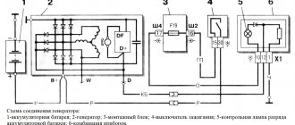
Connection diagrams
wiring diagram for an electric motor with a starting capacitor
The circuit that has a starting capacitor in the network has become more widespread.
This scheme has certain nuances:
- The starting winding and capacitor are turned on when the engine starts.
- The additional winding operates for a short time.
- The thermal relay is included in the circuit to protect the additional winding from overheating.
If it is necessary to provide high torque during startup, a starting capacitor is included in the circuit, which is connected together with the working capacitor. It is worth noting that quite often its capacity is determined empirically to achieve the highest starting torque. Moreover, according to the measurements taken, the value of its capacity should be 2-3 times greater.
The main points of creating an electric motor power circuit include the following:
- From the current source , 1 branch goes to the working capacitor. It works all the time, which is why it got its name.
- In front of it there is a branch that goes to the switch. In addition to the switch, another element can be used that starts the engine.
- after the switch . It operates for a few seconds until the rotor picks up speed.
- Both capacitors go to the motor.
In a similar way, you can connect a single-phase electric motor.
It is worth noting that the working capacitor is present in the circuit almost constantly. Therefore, it is worth remembering that they must be connected in parallel.
Replacement
Removing the capacitor of the VAZ 2110 generator and checking it is carried out in the following order:
- Disconnect the battery (just disconnect the negative terminal);
- Disconnect the excitation wire (wire block at terminal “D”);
- Using the “10” key, unscrew the “B+” output wire;
- Remove the generator belt;
- Unscrew the fixing nut, the adjusting bolt and remove the belt tensioner bar;
- We take out the lower fastening bolt, first use a key “13” and unscrew its nut;
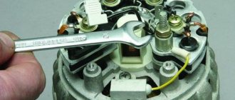
- Carefully pull out the generator itself (see photo).
Generator removal process
Next, we begin to get directly to the “culprit” of the repair:
- We remove the plastic protective casing by pressing the three latches on its body:
- We unscrew the two screws securing the brush holder and carefully, trying not to damage the brushes, pull out the assembly itself, simultaneously disconnecting the wire block from it;
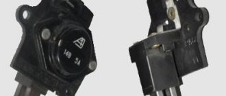
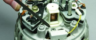
- Unscrew the nut securing the bolt and remove the tip of the condenser contact wire along with the spring and spacer washer;
Capacitor Contact Wire
- Unscrew the fastening screw and remove the “victim”.
Removing the capacitor of the VAZ 2110 generator, video
Malfunction of the VAZ 2110 generator relay
The regulator performs the function of a kind of stabilizer. Thanks to it, the voltage of the vehicle’s on-board network is the same, regardless of the number of revolutions of the running engine. Essentially, a regulator is a relay that closes and opens a circuit.
It happens like this. The voltage dropped below the required value, or rose above the norm - the relay disconnected the generator from the network. The voltage has reached the desired range - the regulator connected the device. There are no electromechanical elements in the VAZ-2110 generator relay. It is built on semiconductors. In addition, its design also includes a brush holder with brushes. It is almost impossible to repair the regulator on your own. It's easier to replace it with a new one.
Checking the functionality of the relay takes no more than five minutes. Yes, and there is no need to disassemble anything here. The diagnostic procedure is as follows. We start the engine and warm it up to operating temperature. Turn on the low beam headlights and the heater fan. Using a tester turned on in voltmeter mode, we measure the voltage at the battery terminals. The voltage should not go beyond 13.2 - 14.7 V.
If it is higher or lower, the relay is faulty. A regulator is considered faulty if its brushes are damaged or excessively worn. The minimum length of brushes is 5 mm.
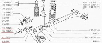
Checking the tensioner belt of the VAZ 2110 generator
Checking the tension of the VAZ 2110 generator belt must be carried out periodically. If the tension is weak, the alternator belt may simply slip, especially during wet weather. As a result, poor belt tension can lead to insufficient battery charging. But you should not overtighten the alternator belt; this will lead to rapid wear of the belt itself or its unexpected break. In addition, when the belt is overtightened, the generator bearings are subject to additional stress and wear out quickly. Below is a schematic drawing that will help you understand how to properly tension the VAZ 2110 alternator belt.
Examination
The capacitor is checked using a tester with a range of one to ten megaohms or a megohmmeter. If the capacitor is working properly, the test picture should look like this:
- The initial tester readings are equal to infinity;
- We connect its probes to the contacts;
- At the moment of contact, the resistance readings decrease, and then again go to infinity.
Otherwise, in the case described above, replace the capacitor, since its price is not high.
Advice! When purchasing a new one, it is advisable to carry out this check in the store itself to avoid purchasing low-quality spare parts.
Since the entire assembly occurs in the reverse order and does not represent anything new, this could be the end of the article. But I consider it necessary to advise you to check the voltage regulator as well, as they say: once the drinking has begun, cut the last cucumber! The check is simple and won’t take much of your time:
- We connect a 12-volt control light bulb to the brushes and apply a voltage of 12 volts (“plus” to the terminal, “minus” to ground) - the light comes on;
Replacement in the generator for VAZ 2110
- Then in the same circuit we apply a voltage of 15-16 volts - the light bulb should not light up.
Attention! It is also necessary to make sure that the brushes are easy to move, that they are not chipped or cracked, and that their length is at least five millimeters, otherwise the regulator must be replaced.
I hope the principle is clear: if the light is on in both cases or, on the contrary, does not light, then there is a malfunction of the voltage regulator relay. With that, let me say goodbye, see you again)))
How does this component work?
The products protect electronic components from various types of interference and are used in a variety of systems in your car. The key function of the device is filtering - for example, in car audio. Without a capacitor, the music system will not work well: there will be extraneous noise, interference and changes in volume. All this is a consequence of voltage surges in the car's electrical network.
Capacitors are found in many parts of the car. They act as buffers between batteries and other electronic devices. Without such a product, it is impossible to function not only the acoustics, but also the contact mechanism in the ignition distributor.
In the photo: diagram of the battery ignition system with digital designation of components:
The principle of operation of the VAZ 2110 generator
When starting the engine, starting current is supplied to the starter from the battery. But the battery itself does not produce energy, but only accumulates it and then releases it. If you use only the battery to power all consumers, it will quickly discharge.
A car generator produces electricity, charges the battery and powers the vehicle's on-board network while the engine is running (when it reaches a certain crankshaft speed). Car generator The generator begins to produce electric current starting from the idle speed, however, it reaches optimal operating mode when the engine reaches 1600-1800 rpm or more.
Types of Automotive Capacitors
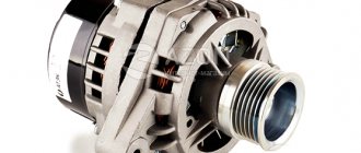
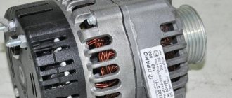
- For the generator. It supplies electricity to a running generator, prevents voltage surges in the ignition, and eliminates radio noise. If there is no capacitor in the car's alternator, passing traffic will cause a lot of noise on the radio. Thanks to this product, it is possible to protect against discomfort on the road.
This is what a car capacitor looks like
- For the subwoofer. The auto amplifier provides fuller bass saturation and expands the frequency range, but it greatly increases current consumption, which leads to problems with headlights and poor quality of low-frequency reproduction. A well-functioning capacitor is a guarantee of protection against problems.
How to understand that a device needs diagnostics
Various signs indicate a faulty capacitor. Headlights that flash in time with the bass of the car speakers mean that the car's electronic components are not receiving enough voltage. In some cases, the signals begin to become distorted, and individual components of the machine do not work correctly.
The ignition capacitor is responsible for producing a spark that ignites the air-fuel mixture in the engine cylinder. If the spark has a weak red color and appears unevenly, if the car cannot be started normally, it is likely that there are problems with the capacitor.
It is important to avoid problems with the ignition capacitor. They arise for three reasons:
The first two options are especially insidious, since the ignition does not immediately fail. The components continue to function, although the spark may no longer have the required power level. The main signs of a breakdown in such a situation are instability of the engine at idle and problems with starting. Be sure to check the capacitor and replace it if necessary! If this is not done, sparks from the breaker will cause the contacts to burn, which will damage the power unit.
Model overview
There are several popular models that can be found on sale.
It is worth noting that these models differ not in capacity, but in type of design:
- Metallized polypropylene versions of the SVV-60 brand. The cost of this version is about 300 rubles.
- NTS film brands are somewhat cheaper. With the same capacity, the cost is about 200 rubles.
- E92 – products of domestic manufacturers. Their cost is small - about 120-150 rubles for the same capacity.
There are other models, often differing in the type of dielectric used and the type of insulating material.
How to check functionality
A reliable way to identify a fault is to use an ohmmeter or multimeter in ohmmeter mode. For the most complete testing, prepare the following tools:
- the measuring device itself;
- portable lamp;
- crank handle.
Location of the capacitor in the ignition system
The main check is performed in the following sequence.
- We switch the ohmmeter to the upper measurement limit mode.
- We connect one terminal of the capacitor to the housing for discharge. We connect one of the ohmmeter probes to the tip of the wire, the other to the body.
- If the indicator quickly deviates to “zero” and then smoothly returns to “infinity” - everything is in order. When changing polarity, the indicator quickly approaches zero. If the value “infinity” is immediately displayed, replacement is required.
Connect an ohmmeter to the capacitor
Instructions for checking a car capacitor on video
Purpose and benefits
Capacitors of the type in question are used in the connection system of an asynchronous motor.
In this case, it works only at the time of start-up, until the operating speed is reached. The presence of such an element in the system determines the following:
- The starting capacitance makes it possible to bring the state of the electric field closer to circular.
- is being carried out .
- increases and engine performance improves significantly.
Without the presence of this element in the system, the service life of the engine is significantly reduced. This is due to the fact that a complex start-up leads to certain difficulties.
The AC mains can serve as a power source when using this type of capacitor. Almost all used versions are non-polar; they have a comparatively higher operating voltage for oxide capacitors.
The advantages of a network that has a similar element are as follows:
- Easier engine starting.
- service life is significantly longer.
Checking without a multimeter
- We disconnect the wires coming from the capacitor and the ignition coil from the breaker. This is where a portable lamp comes in handy. To test the product, connect it to the interrupt terminal, then activate the ignition. Has the lamp turned on? The capacitor is not working properly.
- Another method of checking the performance of the product is to charge the ignition coil capacitor with high voltage current and then discharge it to the housing. If a spark appears between the ground and the capacitor wire and a characteristic click is heard, everything is in order. No reaction? This means there is a breakdown in the capacitor.
- Disconnect the black wire from the breaker terminal that comes from the ignition coil. Disconnect the capacitor wires from the breaker. Turn on the ignition and touch one wire to the other. If there is a spark, something is wrong. Most likely it is a breakdown of the capacitor.
- Using the crank handle, turn the engine crankshaft and remove the cover from the ignition distributor. Turn on the ignition. You can evaluate the performance of the capacitor by monitoring the sparks that occur here. If a breakdown occurs, the breaker contacts will spark strongly. Another sign of a malfunction is weak sparking between the housing and the main high voltage wire.
The condition of the capacitor can be easily checked even on the road. Carry a multimeter with you and be prepared to use it - this way you will get rid of discomfort while driving and avoid the risk of serious damage.
Common malfunctions (signs) of the VAZ 2110 generator
So, it is very easy to determine that it is the generator that is acting up; just know a few basic signs of this - here they are:
- The device does not perform its main function, that is, it does not produce current. In this case, the car is driven only by the battery. Moreover, in this case you will not be able to travel far.
- The drive belt is spinning.
- The generator brushes are faulty.
- The rotor clings and touches the stator.
- There is no wire contact with the battery.
- The device begins to make a lot of noise.
- The battery does not charge while driving.
All these signs are very specific and only an experienced driver can identify them. However, if you have even slight doubts about the performance of the generator of VAZ 21099, 2109, 2110 cars.
How to check a capacitor.
There is one story going around: you don’t need a multimeter to test a capacitor. Bad schoolchildren bullied weaker children using extravagant methods. They charged a large container with a socket and gave them an electric shock. Checking the functionality of the main capacitors of a switching power supply is not difficult. In a personal computer, the voltage reaches 650 volts; if you touch it, it will shake violently. Avoid reaching with a screwdriver. The arc temperature is so high that the desire to know the capacitance of the capacitor can result in good practical welding skills. For discharge purposes, craftsmen use a cartridge equipped with an Ilyich light bulb. The high reactive impedance of the spiral will make it easy to solve the problem of how to test a capacitor with a multimeter.
How to test a capacitor with a multimeter
There is one story going around: you don’t need a multimeter to test a capacitor. Bad schoolchildren bullied weaker children using extravagant methods. They charged a large container with a socket and gave them an electric shock. Checking the functionality of the main capacitors of a switching power supply is not difficult. In a personal computer, the voltage reaches 650 volts; if you touch it, it will shake violently. Avoid reaching with a screwdriver. The arc temperature is so high that the desire to know the capacitance of the capacitor can result in good practical welding skills. For discharge purposes, craftsmen use a cartridge equipped with an Ilyich light bulb. The high reactive impedance of the spiral will make it easy to solve the problem of how to test a capacitor with a multimeter.
Capacitor Testing Process
You'll see, anyone can check a capacitor with a multimeter. A non-polar capacitor or a ceramic capacitor makes little difference; the rating determines a lot. However, hybrid technology can bring surprises. It is clear that removing the SMD capacitor is a serious matter (most people cannot do it). Then carry out indirect tests, for example, comparing readings with a known working device.
- If you bother to turn the multimeter in the opposite direction, you will see not a discharge of the capacitor, but the failure of another brainchild of Chinese industry. It is useful for beginners to know one thing: the contacts of the multimeter are labeled, avoid neglecting to study the appearance of the device.
- The black wire serves as neutral (ground, neutral). Signed Com (English common), marked with a grounding symbol.
- Opposite the other terminals are limits. Here's the one he's working in, stick it there. The red wire is used for this; some multimeters refuse to work if the connection is made incorrectly.
Check the capacitance of the capacitor with a multimeter
It is easier to check the electrolytic capacitor with a multimeter. It's better to start with visual inspection. Faulty electrolytic capacitors noticeably swell. On foreign models, a special cross-shaped slot is made in the upper part of the cylinder to guarantee a fault indication. External signs are silent - you need to grab a multimeter. First, we are guaranteed to discharge the element. Usually there is no voltage, but sticking a bare screwdriver or a piece of wire is a stupid idea. It’s a good idea to create a spark gap with your own hands, using a socket screwed into a light bulb. The gizmo is widely used by repairmen of TVs and switching power supplies. A few words regarding the process: when the capacitor is discharged, you can grab the tester.
In some modes, a voltage of 5 volts comes out at the contacts of the multimeter. Required to evaluate parameters. For example, when measuring resistance, a multimeter simply divides the voltage by the current and gets the desired value. The first digit is known - 5 volts (determined by the tester model). The call is carried out in the same way. 5 volts are supplied to both ends. Some zener diodes break through. It is not possible to ring such elements on digital multimeters.
Knowing these things, we understand what to do next:
We connect the terminals in resistance measurement mode to the contacts of the discharged capacitor. A charging circuit is formed, formed by the internal resistance of the multimeter, the capacitance. At first the current is infinity, then it drops, reaching zero. Along the way, the resistance will begin to grow from zero to infinity. Any capacitor with an operating voltage above 5 volts can be checked in this way. The only trick can be thrown away by polar, for example, electrolytic containers. At the same time, we monitor the correct location of the probes (red, black). Now let's do the analysis. We found out whether the capacitor is suitable, there are some features. We discussed 5 volts on the multimeter probes, the value greatly depends on the model. We can measure at the ends of a known good capacitor: while we ring the contacts, the capacitance will be charged to the required value.
So, the voltage of the test sample is very different from the reference readings (you need to take care of receiving it in advance), it is probably broken. We begin to measure the voltage of the capacitor, the internal resistance of the device is inferior to infinity. The potential will begin to slowly fall, we will notice on the screen. We draw two conclusions:
The initial voltage value is much lower than the standard (provided to the contacts by the tester, continuity mode) - there is a leak inside. The parameter normally forms part of the quality factor formula; if the capacitor quickly discharges on its own (without intentionally closing the contacts), the element has served its purpose. The discharge rate can be used to estimate the capacitance size of the capacitor. You can, of course, get confused with defining constants and formulas; it’s easier to conduct a test with known working containers, and then summarize the results in a table. It will become possible to judge the value of a capacitor based on a single discharge rate. The process is reminiscent of assessing blood pressure using a tonometer. We focus on the eye. The capacitance value is determined by the rate of voltage drop on the multimeter display. Of course, more is done offhand; it will be possible to distinguish μF from MF without difficulty. For those thirsty for more, we can report: during RC the charge drops by 63%. Everyone is free to calculate the volt level with a multimeter. Calculate approximately the internal resistance, based on the data obtained, and take an approximate measurement of the capacitance rating of the capacitor.
It is easier to check the electrolytic capacitor with a multimeter. It's better to start with visual inspection. Faulty electrolytic capacitors noticeably swell. On foreign models, a special cross-shaped slot is made in the upper part of the cylinder to guarantee a fault indication. External signs are silent - you need to grab a multimeter. First, we are guaranteed to discharge the element. Usually there is no voltage, but sticking a bare screwdriver or a piece of wire is a stupid idea. It’s a good idea to create a spark gap with your own hands, using a socket screwed into a light bulb. The gizmo is widely used by repairmen of TVs and switching power supplies. A few words regarding the process: when the capacitor is discharged, you can grab the tester.
In some modes, a voltage of 5 volts comes out at the contacts of the multimeter. Required to evaluate parameters. For example, when measuring resistance, a multimeter simply divides the voltage by the current and gets the desired value. The first digit is known - 5 volts (determined by the tester model). The call is carried out in the same way. 5 volts are supplied to both ends. Some zener diodes break through. It is not possible to ring such elements on digital multimeters.
Knowing these things, we understand what to do next:
- We connect the terminals in resistance measurement mode to the contacts of the discharged capacitor.
- A charging circuit is formed, formed by the internal resistance of the multimeter, the capacitance. At first the current is infinity, then it drops, reaching zero.
- Along the way, the resistance will begin to grow from zero to infinity.
Any capacitor with an operating voltage above 5 volts can be checked in this way. The only trick can be thrown away by polar, for example, electrolytic containers. At the same time, we monitor the correct location of the probes (red, black). Now let's do the analysis. We found out whether the capacitor is suitable, there are some features. We discussed 5 volts on the multimeter probes, the value greatly depends on the model. We can measure at the ends of a known good capacitor: while we ring the contacts, the capacitance will be charged to the required value.