↑ VAZ 2110 generator diagram
1 — casing, 2 — “B+” terminal for connecting consumers, 3 — 2.2 μF noise suppression capacitor, 4 — common terminal of additional diodes (connected to the “D+” terminal of the voltage regulator), 5 — holder of positive diodes of the rectifier unit, 6 - holder of negative diodes of the rectifier unit, 7 - positive diode, 8 - negative diode, 9 - voltage regulator, 10 - rear cover, 11 - tightening screw, 12 - front cover, 13 - stator winding, 14 - spacer ring 15 - front bearing rotor shaft 16 - pulley 17 - nut 18 - rotor shaft 19 - cone washer 20 - washer 21 - beak-shaped rotor pole pieces 22 - stator core 23 - bushing 24 - rotor winding 25 - rear rotor bearing 26 - bearing bushing 27 - slip rings 28 — brush holder 29 — stator winding terminals 30 — additional diode 31 — terminal “D” (common terminal of additional diodes)
Peculiarities
In VAZ 21102 cars, the electrical wiring diagram for carburetors and injectors with 8 or 16 valves is almost identical.
First, let's look at the features that characterize the Tens electrical circuit:
- All devices and equipment are powered from the on-board network. All wires are available in different colors, which greatly simplifies the repair and replacement procedure.
- The negative contact is always ground, that is, ground. The negative contacts are connected to the car body. Typically, the negative wire has black insulation.
- The positive wire is equipped with red insulation. When carrying out repairs, the wires must not be swapped.
- Any electrical equipment or system connected to the on-board network has its own wiring harness.
- The electrical circuit is designed so that when the battery is turned on, all circuits operate under voltage. Accordingly, when performing repair work on the wiring, it is advisable to disconnect the battery terminals to prevent voltage surges.
Carburetor models
The first Ten models, produced since 1998, were equipped with carburetor engines. Injectors began to appear a few years later, but carburetor versions are still widely used by our compatriots. As for the electrical wiring diagram in these cars, there are no fundamental differences in carburetor and injection internal combustion engines. There are some differences associated with the under-hood wiring; they are due to the installation of an improved ignition (author of the video channel IRON BOX).
Therefore, if you suddenly decide to change a carburetor internal combustion engine to an injection one, then most likely there will be no problems with this. The only point to consider is the connection of the fuel pump. In order for this unit to always function correctly, you need to additionally install wiring to power the device to the control module located in the car's interior.
Injector
And although the general electrical circuit of different modifications is almost identical, the latter still have their own characteristics. For example, they install a safety block that uses fusible safety parts. In addition, injection versions are equipped with a large number of different sensors and controllers to ensure optimal operation of the internal combustion engine. Due to the large number of regulators, the electrical circuit of the injection VAZ 2110 itself will be more complex. Moreover, carburetor versions do not have a control unit (ECU).
Photo gallery “Schemes for various modifications of 2110”
↑ Description of generator design 94.3701
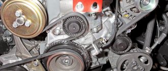
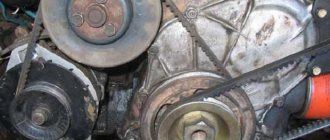
The generator is a synchronous AC electrical machine with electromagnetic excitation and a built-in rectifier using silicon diodes. The generator rotor is driven into rotation from the engine crankshaft pulley (damper) by a poly-V belt.
The stator and generator covers are secured with four screws. The rotor shaft rotates in bearings installed in the covers. The lubricant placed in the bearings at the factory is designed to last the entire service life of the generator. The rear bearing is pressed onto the rotor shaft and is pressed by the rear cover through a plastic sleeve.
The front bearing is pressed and rolled into the front cover and can only be replaced together with it. Its inner race, together with the spacer ring and washer, is clamped by a nut between the pulley and the step on the rotor shaft. The back of the generator is closed with a plastic casing with latches.
The generator stator contains a three-phase winding made in a star configuration (the terminals of the phase windings have a common point). The second ends of the phase windings are connected to a rectifier bridge consisting of six silicon diodes (valves) - three “positive” and three “negative”.
The valves are pressed into two horseshoe-shaped aluminum holder plates in accordance with the polarity (positive and negative - on different plates); one of the plates also contains three additional diodes, through which the excitation winding of the generator is powered after starting the engine. The plates are combined into a rectifier unit mounted on the back cover of the generator (under a plastic casing).
The excitation winding is located on the generator rotor, its leads are soldered to two copper slip rings on the rotor shaft. Power is supplied to the field winding through two carbon brushes. The brush holder is structurally combined with the voltage regulator and is mounted on the back cover of the generator.
The voltage regulator is non-separable; if it fails, it is replaced.
To protect the on-board network from voltage surges during operation of the ignition system and reduce interference with radio reception, a capacitor with a capacity of 2.2 μF (±20%) is connected between the terminals of the “positive” and “negative” valves (between the “+” and “ground” of the generator) on the rectifier block.
electrical problem VAZ21102 engineer
Welcome to ChipTuner Forum.
Theme Options
- print version
Bashkirov Vladimir
Alexey Borisovich
Alexey Borisovich
, not entirely correct, we are talking about two thick brown wires that enter the cabin from the engine compartment and their connection to one point with the pink one from the generator occurs somewhere in the engine compartment. The voltage on the pads was checked first (there are no drops on them), the underestimated one is already “coming” to the cabin.
I also forgot to add that the harness in the engine compartment is hidden in the wing, so it’s not very easy to get to it. That’s why I’m asking – so as not to make too much sense.
Andrei-18
As far as I know, there were never any additional fuses in the 2110. If you are not sure, it is better not to give advice. The standard one on the central locking system is only in the block.
All connections under the hood are visible, the generator, battery, and the harness under the fender come without additional connections. From the battery and generator, to the connector above the fuse box. It’s better to carefully study the diagram; all additional connections are indicated on it. There are simply loose contacts in the connectors, and unstretched masses.
Shuriken_74
miha you're wrong
Let me add: There aren’t very many of these cars, the last one was last week. Symptoms for CD are the same. That’s why I write with confidence, because I know.
Andrei-18
Andrei-18
, everything is fine on the cylinder (there is no voltage drop on it), the masses have been checked - relative to the battery, the drop is only about 0.1 V (considering that the car body is not made of copper - I think within the tolerance). Yes, and I cleaned and stretched all the masses recently (the car was repaired from the cylinder head). As for the connection, I’ll now try to find a diagram and attach a piece of the diagram with this connection.
Alec, thanks, but this version was tested first, and unfortunately the voltage drops to this fuse (also on the cigarette lighter).
the pink wire from the generator splits into two brown and one red (according to one scheme), or purple (according to another), the voltage drops to the connector (which falls into the “circle”). For comparison, the direct wire from the generator (the second pink one) coming to the two-pin connector has the same voltage as that on the generator. All measurements were taken relative to the body. The voltage on the wire near the generator is normal (I pierced the insulation next to the terminal, under the rubber cap).
and one more question (concerns the engine), after repairing the cylinder head, I went to the CO control, and I was given CO = 0.8% (with correction CO = 0.011), CH = 170, CO2 = 10%. When the engine is not running, ADC MAF = 1.06. But on the exhaust pipe there are quite large traces of soot (compared to the classic 06 parents, the pipe there is generally like after the factory). Is this normal or do you still need to check the mass air flow sensor. The car drives normally, there are no twitches at idle (the engine runs smoothly).
↑ Description of operation and testing of generator 94.3701
When the ignition is turned on, voltage is supplied to the generator excitation winding (terminals “D” of the generator and “D+” of the regulator) through the warning lamp in the instrument cluster (the lamp is lit). After starting the engine, the excitation winding is powered by additional diodes of the rectifier unit (the control lamp goes out). If the lamp lights up after starting the engine, this indicates a malfunction of the generator or its circuits.
The “minus” of the battery should always be connected to the “ground” of the car, and the “plus” to the “B+” terminal of the generator. Switching back on will lead to breakdown of the generator valves.
It is not recommended to disconnect the battery when the generator is running (especially on engines equipped with an injection system). The resulting voltage surges in the on-board network can damage the electronic components of the circuit.
The generator valves (and other devices in the vehicle’s on-board network when the generator is connected) should be checked at a voltage no higher than 14 V; a higher voltage (for example, when checking with a megger) can cause damage to the valves. If it is necessary to check the insulation of windings with high voltage, the generator should be removed, and the winding terminals should be disconnected from the rectifier unit and voltage regulator.
The short circuit of additional diodes can be checked by connecting the “+” batteries through a lamp to the “D” terminal of the generator, and “-” to the terminal of one of the stator phase windings. If the lamp is on, one or more additional diodes are broken.
A break in the main valves is determined by a sharp decrease in the output current (voltage drop under load). However, this may also be a consequence of a break or short circuit in the generator windings. A break in the additional valves can be determined by the low voltage at plug “D” (below 14 V) at an average generator rotor speed.
The serviceability of each diode (main or additional) can only be determined with a removed rectifier unit using an ohmmeter or a test lamp.
If the rectifier unit fails, it is recommended to replace it as an assembly. It is possible to replace individual valves, but the main valves will require repressing them in the holder - an operation that requires care and skill.
Replacement and removal of the electric generator
The generator on a VAZ car is removed either for complete replacement in case of failure or to carry out repair work to replace faulty parts. To perform dismantling, prepare a standard set of tools; it is advisable to drive the car into the inspection hole.
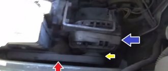
- Disconnect the battery.
- Remove the protective rubber cap from terminal “30” and unscrew the nut and remove it from the wire stud.
- Disconnect the block with wires from the generator connector.
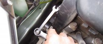
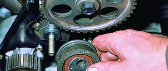
- We loosen the tightening of the generator to the adjusting bar, then lift it all the way up to the cylinder block and remove the belt from the pulleys.
- Completely unscrew the bolt securing the adjusting bar to the cylinder block, then from the bottom of the car unscrew the 2 bolts securing the lower bracket to the block and remove the generator, pulling it out of the engine compartment.
Source
↑ Checking the generator for functionality
- Start the engine, let it run for a few minutes, then, pressing the gas pedal, bring the crankshaft speed to 3000 rpm.
- Turn on all consumers: high beam headlights, heated rear window, heater fan, windshield wiper, hazard warning lights.
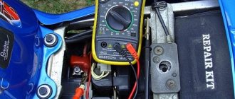
- Measure the voltage at the battery terminals, which should be above 13 V. If this is not the case, the generator windings are faulty (open or short), the voltage regulator with the brush assembly, or the contact rings of the field winding are oxidized.
- To ensure that the voltage regulator is working properly, turn off all consumers except the high beam headlights and measure the voltage again. It should be within 13.2-14.7 V.
- The removed voltage regulator can be checked by connecting a lamp (1-5 W, 12 V) between the brushes, and a power source (DC only!), first with a voltage of 12 V, and then 15-16, to the “D+” and “ground” terminals B. In the first case, the lamp should be on, in the second - not. If the lamp lights up in both cases, there is a breakdown in the regulator; if it doesn’t light up, there is a break or broken contact between the brushes and the regulator terminals. In both cases the regulator should be replaced.
- To check the valves of the rectifier unit, disconnect the wires from the battery, generator and from the “D+” terminal of the voltage regulator.
- Connect the “plus” of the battery through a lamp (1-5 W, 12 V) to the “B+” terminal of the generator, and the “minus” to its body. If the lamp is on, then there is a short circuit in both the block of “positive” and the block of “negative” valves.
- To check the short circuit in the “positive” valves, connect the “+” battery through a lamp to the “B+” terminal of the generator, and “-” to the terminal of one of the phase windings of the stator. If the lamp is on, one or more positive valves are broken.
- To check the short circuit in the “negative” valves, connect the “+” battery through a lamp to the output of one of the phase windings of the stator, and “-” to the generator housing. If the lamp is on, one or more negative valves are broken or the stator windings are shorted to the generator housing.
To prevent short-circuiting of the windings, remove the generator from the car and, having disconnected the windings from the voltage regulator and rectifier unit, check their short circuit to ground using a lamp or ohmmeter. The generator valves can also be checked with an ohmmeter without connecting the battery and test lamp.
Injection "ten"
In addition to the wiring that is provided for the VAZ 2110 - carburetor, "ten" - injector, it is also equipped with a number of fuses that protect almost all of it from the possibility of short circuiting.
Structurally, fuses are not provided only for the electrical supply via a relay wire from the battery, in the car starting and ignition circuit, as well as for the wire going to the generator.
Electrical circuit of an injection car
In addition, the injector (as opposed to the carburetor) is a more complex system, and in order to repair it yourself, you need to understand it well. The controller in this wiring system “reads” the operation of all systems, thereby determining and setting many indicators - calculation of the fuel mixture, etc.
Legend
For ease of maintenance and installation, the electrical wires in the diagrams are made in different colors, identically laid in the car, so that their purpose can be visually determined.
For brevity, colors are indicated by the first letters of the name:
- Blue – “G”;
- Brown – “K”;
- Gray – “C”;
- White – “B”;
- Orange – “O”;
- Yellow – “F”;
- Black – “H”;
- Green – “Z”;
- Pink - "R".
For reference: the red wire is traditionally used to supply power from the positive terminal of the generator or battery. Therefore, in all diagrams contained in the factory instructions, it is designated by the letter “P”.