Engine repair VAZ 21213
In our time of universal automation, many car enthusiasts forget about such a necessary operation as checking the oil level in the engine and hope for the warning light on the instrument panel to go off. However, it is not a fact that if the oil pressure indicator does not panic, then everything is in order in the lubrication system, because it may turn out that it simply burned out or the sensor itself failed, and without oil, as we know, the engine is guaranteed a short and difficult life.
Niva engine characteristics
Years of manufacture – (1994 – present day) Cylinder block material – cast iron Power system – carburetor (21213) / injector (21214) Type – in-line Number of cylinders – 4 Valves per cylinder – 2 Piston stroke – 80mm Cylinder diameter – 82mm Compression ratio – 9 .4 Niva engine capacity 21213 – 1690 cm3. Engine power Niva 21213 – 81 hp. /5200 rpm Torque - 125 Nm / 3000 rpm Fuel - AI93 Fuel consumption - city 11.5l. | track 8.3 l. | mixed 10.5 l/100 km Oil consumption - 700 g per 1000 km Niva engine weight - 117 kg Overall dimensions of the Niva 21213 engine (LxWxH), mm - Oil in the Niva 21213 engine: 5W-30 5W-40 10W-40 15W-40 How much oil in the Niva 21213/21214 engine: 3.75 l. When replacing, fill in about 3.5 liters.
Floating
A floating pin is a pin installed with the required clearance both in the upper head of the connecting rod and in the piston bosses. In this case, axial fixation of the piston pin is carried out due to retaining rings installed in special grooves in the piston bosses. During operation, the floating pin rotates in both the connecting rod head and the piston bosses. With such a connection, it is necessary to ensure the recommended clearance both between the pin and the piston bosses, and between the pin and the connecting rod piston head bushing. In an engine with a floating piston pin, a bronze bushing is installed in the piston head of the connecting rod to reduce friction. Due to the different thermal expansion coefficients of the materials from which the connecting rod, piston pin and piston are made, these clearances are different.
At room temperature, the pin should fit tightly into the bushing of the connecting rod's upper head without play or wobble. And in the piston bosses, in a cold state, the piston should fit with a slight interference fit.
Therefore, before removing or installing a floating pin, the piston must be heated in water to a temperature of 60? ? 85? WITH.
Replacing the piston on Niva 21213 without removing the engine
If necessary, dismantling the ShPG engine can be done on the car without removing the engine
We carry out the work on an inspection ditch or a lift.
Using a 14mm socket, unscrew the two nuts securing the connecting rod cover (the piston must be at BDC).
Using a hammer with a plastic head (or a hammer with a soft metal head), apply light blows to the side surfaces of the cover to loosen its seat on the connecting rod bolts.
Remove the connecting rod cover.
Move the connecting rod up.
Using the wooden handle of a hammer against the connector of the lower head of the connecting rod, push the connecting rod up until the piston exits the cylinder and remove the piston and connecting rod assembly. Similarly, we dismantle the pistons with connecting rods of other cylinders.
We clamp the connecting rod in a vice with soft metal jaw linings.
Using your fingers, carefully (without exerting much force) open the lock of the upper compression ring and remove the upper compression ring.
Remove the lower compression ring in the same way.
Remove the two oil ring discs.
Remove the oil scraper ring expander.
To remove the piston from the connecting rod, use a screwdriver to pry up the retaining ring of the piston pin and remove it from the annular groove of the piston.
In the same way, remove the second locking ring of the finger.
By sliding the piston pin, remove it from the hole in the piston.
Remove the piston from the upper end of the connecting rod.
If some parts of the connecting rod and piston group are not damaged and have little wear, they can be used again.
Therefore, during disassembly, we mark the parts so that they can be installed in the previous cylinder.
Problems when paying with bank cards
Sometimes difficulties may arise when paying with Visa/MasterCard bank cards. The most common of them:
- There is a restriction on the card for paying for online purchases
- A plastic card is not intended for making payments online.
- The plastic card is not activated for making payments online.
- There are not enough funds on the plastic card.
In order to solve these problems, you need to call or write to the technical support of the bank where you are served. Bank specialists will help you resolve them and make payments.
That's basically it. The entire process of paying for a book in PDF format on car repair on our website takes 1-2 minutes.
If you still have any questions, you can ask them using the feedback form, or write us an email at
Order and cost of fingers
The cost of manufacturing fingers for special equipment depends on:
- The purpose of the finger - this affects the choice of material and additional processing;
- Availability of a drawing, sample or sketch;
- Number of parts in a batch.
Separately, we note that if you apply again, the price may be lower, since we will already have all the project documentation.
carries out a full cycle of manufacturing parts: from drawing development and prototype production to applying protective coatings and films. We can guarantee the precision of product processing at every stage.
To clarify the details of cooperation, please contact the managers of FERROPOLIS. This can be done by phone or send a request through the form on the website. In both cases, you will receive qualified advice and a preliminary calculation of the cost of your order.
Final operation
Flushing continues by preparing a special tool. It can be made from an M6 stud, which is rounded and polished on one edge. Since the internal dimension of the PTFE tube is larger than the equivalent diameter of the stud, heat shrink will be required to tightly fit the two mating elements.
Regardless of what kind of oil is in the Chevrolet Niva engine, follow the following sequence:
Cut the end of the tube into 20 millimeters and bend it like a propeller. It is advisable to make the so-called mixer from fluoroplastic. This is due to the fact that this material is resistant to various types of acids, alkalis and oxidizing agents.
It is important to remember here that Dimexide is a rather aggressive substance that can simply corrode ordinary plastic and ruin high-quality plastic. At the same time, obtaining decomposition products will be very problematic.
Next, you will have to “dive” under the car, remove the engine protection and boot. This way you will be able to get to the crankshaft retaining bolt. Unscrew the spark plugs and insert metal pins of suitable size into the vacated holes. Use the crankshaft bolt to turn the mechanism clockwise until the installed “skewers” are in a row. Using a hair dryer, heat Dimexide in a suitable container and pour 100 milliliters into tubes.
Do-it-yourself Chevrolet Niva repair
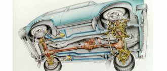
The engine is not connected to the front axle gearbox, and the way the gearbox is designed is a rather unique solution. The upgraded braking system provides increased driving safety. The domestic manufacturer AvtoVAZ included in the design of the car the presence of a front chassis and transmission from the good old Niva. This device has long strengthened its reliable status due to its high structural strength. The classic version is equipped with an adjustable steering column, central locking, electric window lifts and a radio. Any car enthusiast can be convinced that the Niva-Chevrolet is a car created according to all the canons of modern technology.
As for repairing gearboxes, it has its own characteristics. It is worth knowing that the rear and front parts do not differ in structure, but the front gearbox has a design that is somewhat inconvenient for reassembly. Repair of these devices is carried out according to the type of failure.
To reassemble, remove the bracket cover. If you need to install a driven gear, you should study the manual from AvtoVAZ in advance. It is necessary to distinguish between markings written with an electric pencil. Thanks to these markings, you will be able to find out how thick the washer is. With proper skill and luck, this can be determined immediately. Final assembly is carried out using the oil seal and spacer bushing. The lock must be engaged; after pulling the yokes, the repair of the gearbox will be completed. This kind of overhaul is done when parts need to be cleaned. If you do not have experience and knowledge in this area, you should not try disassembling and reassembling yourself.
To adjust the yoke nut, you will need a special tool that will allow you to carry out the procedure with greater convenience. Common faults include a bad gear, broken seal, or broken bearing. Most often, these parts are subject to wear due to the lack of proper lubrication or transmission fluid. When performing maintenance, check the levels of fluids or components of the gearbox. If necessary, you can replace the parts with new ones.
Lada 4×4 3D Gan-Gan › Logbook › Motor capital 21213
Hi all. 3 years ago I bought a Niva, an old Niva. for rides, fishing and fishing. its price was a purely symbolic 27 thousand, in fact the price of a bicycle, or a boat propeller for my boat with an outboard motor))). at the same time, the car could move itself. electrically, a lot of things didn’t work, the appearance was 3-, the condition of the chassis was 3, the engine was 3-. tires are shit! but the price! I had a laugh with a friend and I took her. It’s one o’clock in the morning, we are looking for an ATM in the village, writing a written statement and shaking hands. home on your own. further debriefing and so on. repair\modernization, i.e. NIVORY. In half a year we have repaired the gearbox and front axle. another year later the engine gave up its life, so what do you want from a car for 27 sput? ))) that's right - documents! the rest is all done. We removed the engine and installed the contract. the choice was difficult. the contract did not fail. I won’t say that I got shit, but it’s not great (the price is 12 thousand. Well, that’s also funny). skated for 2 years, upgraded to an injector. and he didn’t give any special problems. never let me down given his condition. in principle, it was possible to skate him and skate him until the total. but I need it! ))) I want a new one! But I don’t want to leave the store due to personal convictions and experience I’ve read. and my native number entered in the STS would somehow warm me up))) in general, I decided to buy capital. native dead engine, or rather only the bottom, because I had no intention of putting the injection head from 2123 anywhere. just change the bottom. Easy to say, difficult to do! CAPITAL bottom 21213, to begin with, we disassemble everything and repair defects. Let me remind you that the engine simply stopped starting for a reason unknown to me at the time. the analysis gave the following. 1. “tar”. he was everywhere. camshaft, cylinder head, crankshaft. The knee was left for repair. it was barely washed and purged. the knee channels were soaked for 2 days in the solution. and sulked until clean gasoline came out.
the head is not killed. let's move on. how to make a cylinder head capital, see the manual. it doesn't take long and isn't that expensive. but it must be done. in my case, the head was done in the fall, when I installed the injector, and in the winter in February again, when the key on the camshaft was torn off, followed by the bending of bugs (we went to a competition and our crew simply did not get there under its own power. sad and funny). so I did another capital rebuild of the cylinder head with the replacement of the camshaft (I didn’t like it right away, but a broken key is a one in a thousand case!). 2 in a row is too much. I decided not to make the third one. 2. piston. This is where the “waiter” came out. This is a crumbled piston of the 1st cylinder. (I can’t find a photo)
How to flush the Chevrolet Niva engine correctly?
Step-by-step instructions for performing the said process are given below:
- Remove the dipstick by treating the element with Dimexide. To do this, you will need to unscrew the E12 clamp bolt and pull the dipstick up. This may cause a small amount of oil to spill.
- Then turn the probe over without removing the cable, pour the specified composition into the container, and then heat the tube with an industrial hair dryer. The paint will begin to peel off in layers in just a matter of minutes.
- The dipstick is turned over again, the paint is removed from it in the usual way, and the element is washed with water. It is imperative to check that there are no paint residues left inside the measure, after which it is placed in its seat.
- The engine of the Chevrolet Niva (VAZ-2123) is warmed up and driven to a hill.
Build process
- Before installing the piston into the cylinder block, we put a special mandrel on it, which, when clamped, pulls the rings into place.
- We place the piston and connecting rod in the cylinder, using the handle of a previously used hammer to push them to the end.
- You need to make sure that the numbers of the connecting rod and the cap match. We insert bolts, liners, and combine the installation lugs with a special recess.
- The nuts are tightened to a certain point. To measure force, you need to use a special key that determines the moment. The reading of the measuring device should be in the region of 50.51 Nm.
Before installing the parts, they are lubricated on all sides with the used motor oil. If this is not done, the elements in direct contact will begin to wear out faster. Further installation work is carried out in reverse order.
Why is the piston pin difficult to lighten?
The primary task of modern engine designers is to increase power and, at the same time, reduce engine weight. In order to reduce the weight of the entire unit, it is necessary to lighten the parts by any available means.
Lightening the piston pin is not easy, since this part is constantly under severe stress. Lightweight and strong alloys that can be used to produce piston pins are expensive, and the cost of the product increases significantly. As a result, most modern engines use alloy steel pins, the same as those used a hundred years ago.
Installing the piston pin
Installing a fixed piston pin
To install a fixed pin, the connecting rod must be heated in an electric muffle furnace to a temperature of 240? C. (In the absence of a muffle furnace, the connecting rod is often heated on a simple electric stove). The connecting rod cools quickly, and the pin must be installed very accurately in the axial direction, so do this only with the use of a special tool. It must be remembered that for each piston diameter there is its own device, although they are all similar to each other, some sizes of devices differ, but this is not visible to the eye. Place your finger on the fixture
Taking all precautions, remove the heated connecting rod from the muffle furnace and quickly secure it in a vice. Using a special tool, insert the pin into the piston and connecting rod, strictly following the instructions in the Repair Manual
Everything must be done quickly, since the connecting rod cools down very quickly. And after the connecting rod cools down, it will not be possible to change the position of the pin.
- Device handle
- Pin centering flange
- Installable finger
- Guide sleeve
- Cap nut
Special device for installing the piston pin of a VAZ car.
Installing pistons in block 21213
1. Remove the piston pin retaining rings from the piston, remove the pin and disconnect the connecting rod from the piston. Remove the piston rings. 2. The connecting rod bolts are pressed into the connecting rod. Therefore, in order not to disturb the fit of the bolt in the connecting rod, it is not allowed to press the bolts out of the connecting rods when disassembling the engine and connecting rod-piston group. 3. If some parts of the connecting rod and piston group are not damaged and are slightly worn, then they can be used again. Therefore, when disassembling, mark them in order to later assemble a group with the same parts and install them in the same engine cylinder. 1. Before assembly, match the pin to the piston and connecting rod. For new parts, the class of pin holes in the connecting rod and piston must be identical to the class of the pin.
| 2. For used parts, for proper mating it is necessary that the piston pin, lubricated with engine oil, enters the hole of the piston or connecting rod by simply pressing the thumb. |
| 3. Also, the piston pin, lubricated with engine oil, should not fall out of the piston or connecting rod bore if the piston is held as shown in the figure. |
4. Replace the finger that falls out with another one of the next category. If a third category pin was inserted into the piston, replace the piston, pin and connecting rod. 5. Assembly of the connecting rod and piston group is carried out in the reverse order of disassembly. 6. After installing the piston pin, lubricate it with engine oil through the holes in the piston bosses. 7. Lubricate the piston grooves and piston rings with engine oil. 8. Orient the piston rings so that the upper compression ring lock is at an angle of 45° to the piston pin axis, the lower compression ring lock is at an angle of approximately 180° to the upper compression ring lock axis, and the oil ring lock is at an angle of approximately 90° to the lock axis of the upper compression ring. 9. Install the lower compression ring with the groove down (see Fig. Marking of the piston and connecting rod). 10. If the ring is marked “TOP” or “TOP”, then install the ring with the mark up (towards the piston bottom). 11. Before installing the oil scraper ring, check that the joint of the spring expander is located on the side opposite to the ring lock.
VAZ-21213 (Niva). Checking technical condition
1. Clean the piston from carbon deposits and remove all deposits from the lubrication channels of the piston and connecting rod. 2. Inspect the parts carefully. Cracks of any kind on the piston, piston rings, pin, connecting rod and its cover are not allowed. 3. If there are deep marks on the working surface of the liners, replace the liners with new ones.
Niva engine characteristics
Years of manufacture – (1994 – modern times) Cylinder block material – cast iron Power system – carburetor (21213) / injector (21214) Type – in-line Number of cylinders – 4 Valves per cylinder – 2 Piston stroke – 80mm Cylinder diameter – 82mm Compression ratio – 9 .4 Niva engine capacity 21213 – 1690 cm3. Engine power Niva 21213 – 81 hp. /5200 rpm Torque - 125 Nm / 3000 rpm Fuel - AI93 Fuel consumption - city 11.5 l. | track 8.3 l. | mixed 10.
5 l/100 km Oil consumption - 700 g per 1000 km Niva engine weight - 117 kg Overall dimensions of the Niva 21213 engine (LxWxH), mm - Oil in the Niva 21213 engine: 5W-30 5W-40 10W-40 15W-40 How much oil is in the Niva engine 21213/21214: 3.75 l. When replacing, fill in about 3.5 liters.
Niva engine life: 1. According to the plant – 80 thousand km 2. In practice – up to 150 thousand km
TUNING Potential – 200 hp. Without loss of resource - 90 hp.
The engine was installed on: VAZ 21213 “Niva”VAZ 21214 “Niva”Chevrolet Niva
Chevrolet Cruze engine assembly
Note: The pin is inserted into the upper head of the connecting rod with an interference fit, therefore, to facilitate assembly and maintain its fit, it is recommended to heat the connecting rods by placing their upper heads for 15 minutes in an electric furnace heated to 240°C. The heating temperature of the connecting rod can be controlled using a thermochromic pencil. To properly connect the pin to the connecting rod, press in the pin as quickly as possible, since after it cools down, the position of the pin cannot be changed.
Warning: When installing, do not open the rings more than necessary to avoid deforming or breaking them.
Notes: Install the lower compression ring with the groove down (shown by the arrow) in the second groove.
The “Y” mark on the compression rings should face up.
Note: The locks of the upper and lower rings of the composite oil scraper ring should be located at a distance of 25-30 mm to the left and right, respectively, of the expander lock.
Notes: In the bed of the middle (third) main bearing, place an increased thickness liner with support shoulders.
Install the liners so that the installation lug of the liner is aligned with the notch on the bed.
Note: The upper and lower main bearing shells may differ in the location of the oil supply hole. Install the liners so that these holes coincide with the holes in the oil supply channels in the main bearing support beds. After installing the liners in the sockets, their ends protrude slightly, so to ensure proper orientation of the liners when final tightening the bearing cap bolts, make sure that both ends protrude equally.
Warning: Use a soft-faced hammer made of brass, lead, or polyurethane to install the crankshaft bearing caps. It is prohibited to install covers by tightening fasteners, as this will damage the seating surfaces of the covers and the cylinder block.
Warning: Be sure to replace the main bearing cap bolts with new ones.
Note: When installing pistons into cylinders, the mark (triangle) on the piston and the lettering on the connecting rod must face the front of the engine.
Warning: Install the piston into the cylinder carefully so as not to damage the crankpin with the lower end of the connecting rod.
Helpful advice: After assembling the engine, it is recommended to run it on a stand. Since this cannot be done outside of special repair organizations, after installing the engine on the car, run it in a simplified cycle in the following order.
1. Make sure that the throttle valve drive is adjusted correctly, fill in oil and coolant, and check the tightness of all connections.
2. Start the engine and let it run without load for the next cycle. Do not operate the engine at maximum speed.
| Crankshaft rotation speed, min-1 | Operating time, min |
| 820-900 | 2 |
| 1000 | 3 |
| 1500 | 4 |
| 2000 | 5 |
3
During operation, check the tightness of the engine and its systems, oil pressure, pay attention to the presence of extraneous noise
4. If unusual noises or other malfunctions are detected, stop the engine and eliminate their cause.
5. When you start using the car, follow the regimes provided for the break-in period of a new car.
Video about “Engine Assembly” for Chevrolet Cruze
Capital Aveo, Cruze, Lacetti 1.6 - F16D3. Part 4. Engine assembly.
Capital Aveo, Cruze, Lacetti 1.6 - F16D3. Part 2. Engine Troubleshooting..
Chevrolet Cruze belt replacement, caps, oil seal. repair at Vadim's.
Chevrolet Cruze service instructions
Repair of central piston group
To replace the piston VAZ 21213 we need a pit or overpass and a standard set of tools.
Dismantling the cylinder head
So:
- The very first action at the beginning of each repair is to de-energize the vehicle's power supply system - remove the battery terminal;
- Drain all fluids from the lubrication system and cooling system;
- We remove all the “attached” equipment from the cylinder head: carburetor, ignition distributor with high-voltage wires, exhaust pipe, starter;
Attention! When disconnecting the exhaust manifold and the exhaust pipe, do not lose the metal sealing ring.
- Disconnect the wires from the oil and coolant temperature sensors;
- Remove the cylinder head cover;
- We unscrew the bolt securing the sprocket on the camshaft and remove it along with the chain;
Camshaft sprocket with chain
- We take out the shaft along with the valve tappets and bearing housing;
Removing the camshaft
- We remove all hoses that will get in the way when dismantling the cylinder head;
- Using an extension and a socket, unscrew the block head and remove it.
Removing the block head
Removing the pallet
Begin:
- Remove the engine splash guard and the sump protection plate;
- On the side engine mounts, unscrew the nuts securing them to the cross beam brackets;
Unscrewing the gearbox bracket
- We disconnect the front axle gearbox and the engine bracket in order to raise the power unit;
- Raise the engine with a jack and insert wooden blocks between the supports and brackets of the transverse beam;
- Remove the jack from under the car;
- Using a ten-point socket, unscrew the twelve bolts securing the pan to the crankcase.
Attention! We remove the pan carefully, trying not to tear the gasket.
- Remove the oil pump intake filter.
- Next, unscrew the nuts of the lower connecting rod caps and remove them along with the liners.
Replacing the piston group and rings
We take out the connecting rods
Advice! Mark their location and order for later installation of each cover and liner in its place.
- Carefully, using a wooden block (usually a hammer handle), after raising the piston to top dead center, push the connecting rod up;
Dismantling the connecting rod
Attention! When installing and dismantling, you should pay attention to the markings of connecting rods and pistons, where:
- arrow indicating the position of the piston in the cylinder;
- repair number size;
- class of the piston itself;
- piston pin hole class;
- class of connecting rod, or rather its holes for the piston pin;
- number of the cylinder for which the connecting rod is intended.
Marking
Checking the condition of the pistons
We clean the piston from traces of carbon deposits and remove all deposits from the lubrication channels of the connecting rod and the piston itself. During inspection, we pay attention to characteristic cracks on the piston, its rings, pins, connecting rods and on the covers, which are a sign of maximum wear. Deep grooves on the working surface of the liners also indicate that they should be replaced with new ones.
Selection of pistons for cylinders
The gap calculated for this pair, provided that they are new, is 0.025-0.045 mm. It is determined by measuring the elements of the piston group (cylinders and pistons) of the same class. For wear, the maximum tolerance is 0.15 mm. If the clearances are exceeded, it is necessary to select new pistons for the cylinders to achieve optimal values. Pistons of various classes (sizes) are supplied to the automotive spare parts market - A, C, E, which are quite enough to select pistons for any size of cylinders, since they, in turn, are also divided into classes that have a margin according to the limiting values of their dimensions. That is, a piston with class C is quite suitable for class B or D cylinders.
Disassembly
So:
- We remove the rings that lock the piston pin from the pistons, take it out and separate the connecting rod from the piston;
- Remove the piston rings.
Attention! Bolts are pressed into the connecting rod with a high tension. As a result, when repairing the connecting rod and piston group, pressing them out is not recommended in order to avoid damaging the seat.
Advice! Some parts may be slightly worn and not damaged, so during disassembly they must be marked in order to assemble the dismantled elements into their own group and into their own cylinder during reassembly.
Installing the piston pin
Installing a fixed piston pin
To install a fixed pin, the connecting rod must be heated in an electric muffle furnace to a temperature of 240? C. (In the absence of a muffle furnace, the connecting rod is often heated on a simple electric stove). The connecting rod cools quickly, and the pin must be installed very accurately in the axial direction, so do this only with the use of a special tool. It must be remembered that for each piston diameter there is its own device, although they are all similar to each other, some sizes of devices differ, but this is not visible to the eye. Place your finger on the fixture
Taking all precautions, remove the heated connecting rod from the muffle furnace and quickly secure it in a vice. Using a special tool, insert the pin into the piston and connecting rod, strictly following the instructions in the Repair Manual
Everything must be done quickly, since the connecting rod cools down very quickly. And after the connecting rod cools down, it will not be possible to change the position of the pin.
- Device handle
- Pin centering flange
- Installable finger
- Guide sleeve
- Cap nut
Special device for installing the piston pin of a VAZ car.
Installing a floating piston pin
To ensure the required clearance (tension) in connection with the pin, pistons, depending on the diameter of the hole for the piston pin and pins, depending on the outer diameter, are usually divided into several size groups (classes). The piston and pin group is usually marked with a colored mark on the inside of the piston crown or boss. On the piston pin, a color mark is usually applied to the end surface. If the piston pin is installed in the piston bore with interference. First, the clearance in the connection between the piston pin and connecting rod is checked. At room temperature (20? C), a finger lubricated with engine oil should enter the bushing of the upper head of the connecting rod under the force of the thumb. After checking the color marks on the piston and pin, we heat the piston in a bath of hot water, which is maintained at a temperature of 60? ? 85? C. A pin lubricated with engine oil should fit easily into the piston bore. After cooling, the pin should be stationary or rotate with force in the piston boss, but rotate easily in the bushing of the upper connecting rod head. Some manufacturers recommend removing and installing the piston pin using a special tool.
Sometimes the piston pin is installed with a set gap both in the bushing of the upper head of the connecting rod and in the holes of the piston bosses. In this case, there is no need to heat the piston, and the pin rotates easily at room temperature both in the upper head of the connecting rod and in the piston bosses. Always use new piston pin snap rings and install the snap rings in strict accordance with the repair manual. The direction of the lock ring gaps, most often, should be directed towards the bottom of the piston. Repair kit consisting of a piston, a piston pin matched to the piston and flat circlips.
Repair kit consisting of pistons, piston pins, piston rings and circlips.
Flat piston pin snap rings
Floating piston pin with O-ring set
In any case, before installing the piston pin, carefully read the repair manual for the vehicle being repaired. Piston pin lubrication A piston pin operating under high mechanical and thermal loads must receive the necessary lubrication. The floating piston pin in connection with the connecting rod piston head is lubricated through a hole in the connecting rod head and bronze bushing. Oil enters this hole from the internal cavity of the piston, where it is sprayed by an oil nozzle or enters through holes in the piston from the oil scraper rings.
Causes of oil waste
Well, in general, this is the second question. First you need to find out where the oil goes from the engine if the leak is not visible from the outside? The debate about the natural waste of oil has been going on for many years. There is only one conclusion - if you don’t want the engine to “eat up” the oil, don’t fill it at all! The point is this. The service life of the engine is ensured by good lubrication, and even more so by the lubrication of the piston rings and, as a consequence, the surface of the cylinders in the form of an oil film. So much for natural insanity.
CPG lubrication
When designing a modern engine, oil loss due to waste is initially 0.1-0.3% of the volume of fuel used . In addition, with different types of operation (river transport, cars, generators), oil burn readings vary significantly! Well, since the engine of the VAZ 21213 is frankly “weak” and, due to the specifics of the vehicle’s operation, operates under increased loads, the passport parameter for oil waste does not last long, after which oil consumption begins to increase significantly. Why? In addition to the mentioned natural burnout, there are several other reasons:
- Oil release through the internal combustion engine ventilation system. The wear of the CPG (cylinder-piston group) directly depends on the pressure of the crankcase gases, whose speeds increase, which contributes to a greater extraction of oil into the atmosphere (in modern cars for “afterburning”);
- A trivial leak in places where engine components do not fit tightly.
Attention: In general, if you see all of the above defects in your car. If you are convinced that the CPG is worn out (by measuring the compression - at least 8 kgf), then replacing the piston rings of the VAZ 21213 is the most economical option for you. In case of such wear of the internal combustion engine, a good owner will, among other things, check the wear of the cylinders, connecting rod liners and, if necessary, replace not only them, but also the entire piston group with valve stem seals. Everything here is limited only by the price of the repair issue.
Downloading a book
After successfully completing the payment (by any method) and returning to the KrutilVertel store from the payment system website, you will be taken to the successful payment page:
The book you purchased will be in your personal account, from where you can always download it.
Please note that after making the payment, you need to return back from the payment system website to the KrutilVertel website. If for some reason you did not return back to the site and closed the payment system tab with a message about the successful completion of the payment, please let us know - we will send you a letter indicating access to download the book
If for some reason you did not return back to the site and closed the payment system tab with a message about the successful completion of the payment, please let us know - we will send you a letter indicating access to download the book.
Sequence of operations for removing pistons and connecting rods:
- Remove the cylinder head and oil sump from the engine.
- Rotate the crankshaft until the piston to be removed is at bottom dead center (BDC).
- Undo the cotter pins and unscrew the nuts of the connecting rod lower head bearing mounting bolts and remove the connecting rod cover.
- Push the connecting rod with the piston and remove the set of these parts from the cylinder. Before removing the pistons and connecting rod assembly from the cylinder, you need to check the condition of the upper edge of the cylinder bore. If there is a shoulder here (a premature section of the cylinder mirror), it must be removed with a special cutting tool.
- Mark the piston with the cylinder serial number and check for the presence of the factory mark of the cylinder serial number on the connecting rod and its cap on the side facing the camshaft (see symbols A and 2 in the circle in the figure). The remaining pistons, complete with connecting rods, are removed from the cylinders in a similar way.
Replacing piston rings for VAZ 21214
It is possible to replace the piston system of a VAZ 21213 car without completely disassembling and removing the engine.
To do this, work is carried out on an overpass, possibly in an inspection pit or on a specially made lift. Replacing Niva piston rings can be done with your own hands, for which you need to follow certain recommendations. First you need to drain the oil, remove the pan and pump, which is quite difficult to do when using only a jack. Then: 1. The connecting rod cover is secured with two nuts, which can be unscrewed using a 14mm socket . At this stage, the piston is set to bottom dead center.
2. Using a hammer with a special soft heel, we apply gentle blows to the lid, preferably from the side. This action weakens the fit of the upper part of the housing on the connecting rod bolts of the VAZ 2121 engine.
3. The upper part is then removed without much effort.
4. Lift the connecting rod up with your hands.
5. Using a previously used hammer, we make a kind of lever, for which the handle is pressed against the connector formed by the connecting rod. The load should be medium, we push until the entire structure comes out completely.
6. The rings can only be removed when the piston is completely removed from the cylinder block. The upper part and cylinder are dismantled in a similar way, which allows the piston rings to be replaced.
You can remove the piston rings yourself. To make the task easier, you can clamp the connecting rod in cleats that have soft metal jaws. The replacement procedure is as follows: 1. Use your hands to release the lock without much force.
2. Now you need to remove the upper and lower compression rings.
3. Next, remove the two piston oil ring discs.
4. Remove the expander.
5. In order to replace the piston, the retaining ring is removed.
6. After dismantling the two piston rings, the pin can be freely removed from the hole.
When performing work, it should be borne in mind that some parts will also be in good condition. If necessary, they can be reused by marking the positions with a pencil.
If it is necessary to replace pistons, it should be taken into account that their mass should not differ. The maximum deviation is only 2.5 grams in both directions. You can check the mass using electronic scales, the accuracy of which is a fraction of a gram. A flat feeler gauge is used to check the height gap that is formed between the groove and the ring.
When measuring, the gaps should not exceed the following values:
- The first compression ring is 0.04-0.07 millimeters. The second compression ring is 0.03-0.06 mm. Oil 0.02-0.05 millimeters.
Replacement of rings and seals is carried out in the reverse order. What piston rings to put on the Niva: main size 82 millimeters , article number 21083-1000100-00. As a rule, there is a special table from which you can select the most suitable design option.
3. You need to pay attention to ensure that the numbers of the connecting rod and the cover match. We insert bolts, liners, and combine the installation lugs with a special recess. 4. The nuts are tightened to a certain point. To measure force, you need to use a special key that determines the moment. The reading of the measuring device should be in the region of 50.51 Nm .
Before installing the parts, they are lubricated on all sides with the used motor oil. If this is not done, the elements in direct contact will begin to wear out faster. Further installation work is carried out in reverse order.
Source
Description of the motor device 21213
The basis of the VAZ 21213 engine includes:
- cast iron cylinder block (BC) 21213-1002011;
- block head 21213-100301*;
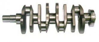
- crankshaft 21213-1005015;
- connecting rod and piston group 21213-10040*.
The main difference between the 21213 engine and its predecessors was the increased cylinder diameter - 82 mm versus 76 and 79 mm. The center-to-center distance of 95 mm remains the same, and allows the block to be bored to a diameter of 82.8 mm. The design of the water jacket has changed. The working volume has increased by 100 cm3, but the engine dimensions have remained the same.
To install the crankshaft in the BC there are 5 supports: one each on the front and rear walls, 3 more on the ebb. The crankshaft parameters provide a piston stroke of 80 mm. The crankshaft is cast from cast iron and consists of 4 connecting rods and 5 main journals. The connecting rod journals have oil channels. The necks are separated by cheeks with counterweights. In previous VAZ engines, balancing counterweights were found only in the outer and central cheeks. The axial movement of the shaft is limited by thrust half-rings.
The piston group for the 21213 engine was developed anew. Pistons 21213-1004015 are cast from aluminum and reduced to a single mass of 347 g. The piston class (A, B, C, D, E) is determined by the outer diameter in increments of 0.01 mm. The shape of the piston is conical in height and oval in cross section. The hole for the pin is 22 mm, offset by 1.2 mm from the piston axis. The finger is locked with rings. There are 3 rings installed on the piston skirt:
- upper compression barrel;
- medium oil scraper with expansion coil spring;
- lower compression scraper type.
The connecting rod 21213-1004045 is forged from steel and processed together with the cover. A steel-bronze bushing is pressed into the upper head of the connecting rod. To fasten the connecting rod, M9x1.0x56 bolts are used.
The aluminum BC head is designed for the VAZ 21213 engine and is designed for compression from 10 bar. Installing a head from other motors may cause it to break. Cast iron seats and guide bushings for 4 intake and 4 exhaust valves are pressed into the head. The valves operate from the camshaft cams. The gap between the valve stem and the cam is adjusted with a bolt.
Related article Gas internal combustion engines
timing belt
The camshaft 21213-1006010 is made of cast iron and rests on 5 journals. The jaws are bleached to increase wear resistance. Axial movement of the shaft is limited by a thrust flange.
The timing belt is driven by a double-row bush-roller chain. In addition to the camshaft, the chain drives the oil pump. The drive is regulated by a semi-automatic tensioner with a shoe and damper. To prevent the chain from falling off when removing the camshaft sprocket, a limiter is provided next to the crankshaft drive sprocket.
Systems
The power supply system in the Niva 21213 engine is a 21073 Solers carburetor. The carburetor unit is two-chamber, the throttle valves operate sequentially. When the first chamber is 2/3 open, the throttle of the second chamber is engaged. At idle, the economizer turns on. The carburetor device includes:
- float chamber;
- 2 dosing systems;
- crankcase gas suction system;
- heating the throttle zone of the first chamber;
- blocking the second camera;
- economizer;
- econostat;
- diaphragm accelerator pump.
The ignition system in the 21213 engine is non-contact. The system is controlled by a switch using distributor signals. In general, the system is classic, without any special features.
Cooling of the motor occurs according to a typical scheme: liquid circulates through the water jacket in the BC and the block head. The pressure is created by a centrifugal pump connected by a belt drive to the crankshaft and generator. The radiator fan impeller works on suction, so in winter the radiator has to be covered with cardboard.
content .. 11 12 19 ..Niva all-terrain vehicle. Connecting rod and piston group
2.8.1. Features of the device GENERAL INFORMATION Main dimensions of the connecting rod and piston group Marking of the piston and connecting rod
| 1 – arrow for orienting the piston in the cylinder; 2 – repair size; 3 – piston class; 4 – hole class for piston pin; 5 – connecting rod class based on the hole for the piston pin; 6 – cylinder number |
Places where it is allowed to remove metal when adjusting the mass of the upper and lower connecting rod heads. Piston
The piston is cast aluminum.
During manufacturing, the weight of the pistons is strictly maintained. Therefore, when assembling the engine, it is not necessary to select pistons of the same weight group. According to the outer diameter, the pistons are divided into five classes (A, B, C, D, E) every 0.01 mm. The outer surface of the piston has a complex shape. It is conical in height and oval in cross section. Therefore, it is necessary to measure the piston diameter only in a plane perpendicular to the piston pin, at a distance of 55 mm from the piston bottom. Based on the diameter of the hole for the piston pin, pistons are divided into three classes (1, 2, 3) every 0.004 mm. The classes of piston diameters and holes for the piston pin are marked on the bottom of the piston (see Fig. Marking of the piston and connecting rod). Repair size pistons are manufactured with an outer diameter increased by 0.4 and 0.8 mm. The bottoms of these pistons are marked in the form of a triangle or square. The triangle corresponds to an increase in the outer diameter by 0.4 mm, and the square - by 0.8 mm. The arrow on the piston crown shows how to properly orient the piston when installing it into the cylinder. It should be directed towards the camshaft drive. Piston pin
The piston pin is steel, hollow, floating type, i.e.
rotates freely in the piston bosses and connecting rod bushing. The pin is secured in the piston by two steel retaining rings. According to the outer diameter, the fingers are divided into three classes every 0.004 mm. The class is marked with paint on the end of the finger: a blue mark is the first class, a green mark is the second class, and a red mark is the third class. Piston rings
Piston rings are made of cast iron.
The upper compression ring has a chrome-plated barrel-shaped outer surface. The lower compression ring is scraper type. Oil scraper ring - with chrome-plated working edges and with an expansion coil spring (expander). Repair size rings are marked digitally “40” or “80”, which corresponds to an increase in the outer diameter by 0.4 or 0.8 mm. Connecting rod – steel, forged. The connecting rod is processed together with the cover and therefore they are individually non-interchangeable. To avoid mixing up the caps and connecting rods during assembly, they are marked with number 6 (see Fig. Marking of the piston and connecting rod) of the cylinder in which they are installed. When assembling, the numbers on the connecting rod and cap should be on the same side. A steel-bronze bushing is pressed into the upper head of the connecting rod. Based on the diameter of the hole in this bushing, the connecting rods are divided into three classes every 0.004 mm (the same as the pistons). The class 5 number is stamped on the upper head of the connecting rod. Based on the mass of the upper and lower heads, connecting rods are divided into classes (see table. Classes of connecting rods based on the mass of the upper and lower heads), marked with paint on the connecting rod rod. Connecting rods of the same weight class must be installed on the engine. The weight of the connecting rods can be adjusted by removing metal from the bosses on the heads to a minimum size of 16, 5 and 35.5 mm (Fig. Places where metal can be removed when adjusting the weight of the upper and lower connecting rod heads). Classes of connecting rods based on the weight of the upper and lower heads
| Mass of connecting rod heads, g | Class | Marking color | |
| top | bottom | ||
| 186 ± 2 | 519 ± 3 | A | White |
| 525 ± 3 | B | Blue | |
| 531 ± 3 | C | Red | |
| 190 ± 2 | 519 ± 3 | D | Black |
| 525 ± 3 | E | Violet | |
| 531 ± 3 | F | Green | |
| 194 ± 2 | 519 ± 3 | G | Yellow |
| 525 ± 3 | H | Brown | |
| 531 ± 3 | I | Orange |
VAZ-21213 (Niva). Selection of piston to cylinder
GENERAL INFORMATION
The calculated gap between the piston and cylinder (for new parts) is 0.025–0.045 mm. It is determined by measuring the parts and is ensured by installing pistons of the same class as the cylinders. The maximum permissible gap (if parts are worn) is 0.15 mm. If a used engine has a gap exceeding 0.15 mm, then it is necessary to re-select the pistons to the cylinders so that the gap is as close as possible to the calculated one. Spare parts include pistons of classes A, C, E. These classes are sufficient to select a piston for any cylinder during engine repair, since pistons and cylinders are divided into classes with a slight overlap of sizes. For example, a class C piston may be suitable for class B and D cylinders.
content .. 11 12 19 ..
Weaknesses of the VAZ 21213 power unit
- Water pump;
- Engine, manual transmission and transfer case oil seals;
- Generator;
- Starter;
- manual transmission;
- Valve cover gasket;
- Cooling system pipe connections;
- Radiator;
- Thermostat;
- Expansion tank;
- Vacuum brake booster.
The water pump (pump) is characterized by frequent failures on new cars after 2,000 km.
Due to poor quality, oil seals require more frequent replacement than required according to the operating manual.
The generator has a high probability of failure. As a rule, it burns out even on new cars that have not reached 4,000-10,000 km.
The starter has a low service life without repair.
On a gearbox, one of the common defects is fifth gear offset. In addition, the gears are not fully engaged.
The valve cover gasket loses its properties over time and allows oil to leak out.
The connections of the cooling system pipes in the places where the clamps are installed are not reliable and lose their tightness very early, which is fraught with loss of antifreeze.
The radiator is leaking. The problem occurs due to the appearance of cracks in the radiator pipe package, accompanied by loss of coolant. This defect has become widespread.
The thermostat does not provide thermal conditions for the coolant in the engine cooling system. The manifestation of this problem is no exception. The cause of the defect is a failure of the valve mechanism inside the thermostat. To check that the thermostat is working properly, after starting the engine, simply place your palm on the lower (outlet) hose, through which hot antifreeze circulates into the radiator for cooling. If the thermostat is working properly, after some time the hose should become hot; if the hose remains cold, the thermostat must be replaced.
The expansion tank cracks and antifreeze leaks out. The appearance of cracks occurs due to the failure of the steam-air valve in the tank plug due to increased pressure.
Vacuum brake booster (VUT). Manifested by a stiff brake pedal. The speed may fluctuate when the brake pedal is pressed, as well as hissing. The problem is solved by replacing failed rubber products and replacing clamps in connections.
Malfunctions and repairs of the VAZ 21213 / 21214 Niva engine
Engine VAZ 21213 1.7 l. carburetor/injection (21214) in-line 4-cylinder with overhead camshaft, Niva timing belt has a chain drive. Based on the 214 engine, the VAZ 2123 engine is produced for the Chevy Niva; the differences in adapting the block for installing a pulley in the engine compartment and mounting attachments are technically almost identical. The main differences between the VAZ 21213 engine and the 2106 are the cylinder diameter is 82 mm, the cylinder head, the Niva 21213 engine block from the 2106 is smaller in height. Among the advantages of the 213 engine, it is worth noting the presence of a chain tensioner (no need to tighten it) and hydraulic compensators (no need to adjust the valves). Disadvantages of the Niva engine - noisy, consumes oil, prone to overheating and vibrations, low resource. The motor has all the problems of the classic series, the 21213 Niva engine still heats up, troits, knocks, etc., what the problems are, for each case, are described in detail HERE, in the problems and malfunctions section.
Broken timing chain on Niva 21214 | Thread Posted by: Anuradha
A furry animal with kind blue eyes, as always, crept up unnoticed... More precisely, there were harbingers. A strange rattling sound after starting the engine began to bother me around the end of winter, but I blamed the starter shield. Then the sound appeared a couple of times while driving around the city at the end of spring, but quickly disappeared. What can happen to an engine that has 68 thousand miles, a hydraulic timing chain tensioner and hydraulic valve compensators? Out of habit, after the 213rd Niva, after 10 thousand miles, I was going to tighten the chain and check the valve clearances, but to my great surprise I did not see the chain tensioner in the engine housing in its normal place. Only the tubes are kind of strange. It turned out that these operations are not required on engine 21214. Those. In general, there is no need to remove the cylinder head cover every 10 thousand kilometers and turn the nuts, setting the required valve clearances to a micrometer, and after one tightening the chain with visual inspection. Here, a cunning hydraulic system invented by smart engineers does everything for us. The engine of my Swallow with the cylinder head removed, a standard starter and a new relay. It can be seen that the cylinders for a mileage of 68 thousand km look like new. The color of pistons 1 and 3 is slightly different, but this is most likely the consequences of a breakdown and an incorrectly functioning timing system. So I drove like this, forgetting about the labor-intensive operation. Then I started having problems with the starter and I replaced it with a KZATEK one. And so, about 10 days before leaving for the big voyage “Around Onega 2019,” a terrible thing happened... And this terrible thing happened not somewhere on the highway, but right in the city, in the center. I drive away from the parking lot near the Market, turn the key to start, and along with the usual sound of the starter, I hear some kind of grumbling noise. The car even seems to start but stalls almost immediately. I drove the starter a couple of times, but the sound was strange, as if there was no load. Naturally, knowing the quality of the spare parts, I began to blame the starter, its crowning glory. Bendix or even a broken flywheel crown. Cursing everything, I asked the taxi drivers to push me, but contrary to usual, the Niva did not start. Well, I think this is a feature of the 214 with its injector. It probably can't be started with a pushrod at all. Nevertheless, I caught the jeep and dragged it a couple of hundred meters with zero results. I was also alarmed that there was practically no rolling resistance with this method of winding. I also thought that there was some kind of problem with the clutch. As a result, I towed the car home, tried to start it again along the way and to no avail, I threw off the starter. The starter works, although for some reason there was a lot of black dirt stuck to the oil on the crown during 3 months of operation. Continuing to sin on the starter, I struggle to get 900 rubles. I finally found a pull-in relay for the standard old Iskorka starter, replaced it and put the original Iskorka in place. The result surprised me a little. The starter rotated the crankshaft freely without encountering resistance. And then it dawns on me that there is no drive to the camshaft. It seems I got it. There were about 10 days left before departure... The photo clearly shows clogs on the pistons in those places where they hit the valves. The whole scale of the problem was not only the complexity, duration and high cost of repairs, but also the lack of competent familiar engine repair specialists. In more than 20 years of driving experience, I have never encountered such a major breakdown and have not repaired anything in the engine at all, only serviced it. I was always surprised that someone’s timing belt broke and the valves turned up - you have to drive a Niva, it’s not a plastic belt, but a double chain. And here it is for you... Nevertheless, through the Retro Garage Museum, I found a service, and most importantly, a person who understands Niva engines. Before the autopsy, there was hope that I would get away with relatively inexpensive repairs and fear, but the reality turned out to be sad. View of the engine from the left side. I also didn’t like the deposits in the cooling system channels from the standard CoolStream Standard antifreeze (green). It was filled from the factory and I continue to use it despite the difficulties in purchasing it. In Perm you can only buy it at the MAZ service center. On the one hand, I was lucky that the chain broke not at a speed of 130 km/h, but when trying to start the engine. But subsequent attempts by the plant with the help of a tugboat did their dirty work. The exhaust valves were bent. Moreover, their guides are deformed. In the process of removing the guides, a special tool was broken and it became clear that no one would guarantee the presence of cracks in the cylinder head, which could then negate all repair efforts. In a situation of temporary time pressure, a decision was made to replace the cylinder head. The costs are higher, but less time is spent. The cylinder head, which cost about 8-odd thousand, already had a valve mechanism, and I still had a certain amount of spare, slightly used parts. When assembling the engine, the hydraulic chain tensioner was thrown out, as the main cause of the breakdown, and replaced with a mechanical one. But not like the ones found on 2121 and 21213, but a cunning one that does not require constant operations to tighten the chain, but tensions it automatically using a spring and is self-locking. They also suggested that I abandon hydraulic valve compensators, but I had already gotten used to a maintenance-free engine and decided to leave them at my own peril and risk.
Removed cylinder head after several attempts to remove valve guides. The ill-fated timing chain tensioner is visible sticking out
The photo shows a split exhaust valve guide of the first cylinder and a difficultly pulled out exhaust valve guide of the third cylinder. In the photo, a split and tightly stuck exhaust valve guide is visible in the 4th cylinder. There appears to be a crack in the 3rd cylinder where the guide was pulled out. One of the exhaust valves with a bent neck is a pitiful sight. Now let's try to reconstruct how the engine breakdown developed and its causes. Most likely the reason is an incorrectly functioning hydraulic chain tensioner. The chain stopped tensioning, but for some reason there was no characteristic sound, or I simply didn’t pay attention, knowing that everything there was tensioning itself. Due to a poorly tensioned chain, when starting cold and at high speeds, the ebonite heads of the tensioner and damper began to break down from vibration. Next, most likely, the damper broke, but the engine continued to work, only making a rattling sound when starting. The chain gradually wears out the abnormally installed remnants of the damper and breaks them out of the fastening, the load on the tensioner shoe also increases and it soon breaks off. Then the chain begins to eat the oil pump sprocket and wears out on its own. Engine 21214 has a pump sprocket with a smaller diameter than 21213. This was done to increase the speed of the low pump (it remained standard) and increase the pressure in the engine lubrication system. After all, now we need to pump oil to the hydraulic tensioner and hydraulic compensators. After some time, the wear of the system becomes critical and when the engine starts, the chain simply breaks...
Timing drive parts. Broken chain, sprockets, a large fragment from the chain tensioner shoe and two fragments from the damper shoe. The photo clearly shows the damage to the oil pump drive gear. the rest of the gears are without visible damage, but I replaced them just in case. One more thing. To my great surprise, the chain of 21214 turned out to be single. On the one hand, its strength decreased, but on the other hand, the mass, and therefore the moment of inertia, decreased. Now it becomes clear that the combination of a hydraulic chain tensioner and a single chain with a smaller oil pump sprocket makes the timing drive system on 21214 less reliable than on 21213, where such a breakdown is practically impossible.
Broken timing chain and broken shoes
Timing chain break and shoe fragments The photo clearly shows the wear of a fragment of the chain guide shoe and damage to the oil pump drive sprocket
Development on the oil pump drive sprocket
Service on Nagorny where my swallow was repaired. As for the Opels and Skodas, you are welcome, but they won’t take the Niva, they did mine through an acquaintance. Some summary. 1. They made my car just beautifully. Repairs cost 10 thousand and spare parts and consumables cost 15 thousand. I received it in my hands 2 days before departure with some fear. What if something goes wrong along the way? I listened for three days, then calmed down. The engine runs noticeably smoother than before, there are no extraneous noises, the car greedily devours kilometers. The gravity has noticeably increased, I feel that 145 km/h is far from the limit. 130 km/h can be maintained at cruising speed, but then another problem arises - in the summer heat, the seals of the gearbox, transfer case and gearboxes melt. As a result, oil leaks. You should adhere to the following considerations when driving in 30 degree heat. Cruising speed is approximately equal to the temperature of the transmission oil. 120 km/h is 120 degrees in the gearbox and transfer case. Accordingly, the seals melt and leak. The optimal cruising speed is up to 105-108 km/h, but when the outside temperature increases >30 degrees, it should be reduced to 90 km/h. To celebrate the successful engine repair, I didn’t care about this limitation and my transfer case oil seal leaked at the exit point of the rear drive shaft. The box was spraying oil through the breather. 2. On Niva 21214, despite the hydraulic compensators and hydraulic chain tensioner, it is necessary to remove the cylinder head cover at least once every 20-30 thousand kilometers and check the condition of the mechanisms. First of all, the timing drive. 3. When purchasing a Niva 21214 after a mileage of 20 thousand, I would recommend replacing the hydraulic chain tensioner with a mechanical automatic one. The issue price is 400-600 rubles. You can, of course, remove the hydraulic valve compensators, returning to design 21213, it’s more reliable, but then you end up with maintenance of the gaps at intervals of 10 thousand km. 4. If extraneous noise occurs in the engine area, do not think that it is the shield that is rattling, but initially assume the worst and look for the source of the noise. 5. If suddenly, when starting the engine, a slight grinding noise is heard and then the starter spins only the crankshaft at idle (you can tell by the characteristic buzzing sound without voltage, but the trouble is that it’s difficult to immediately understand, it’s not every day that the chain breaks. Another indicator is that there is no characteristic “ fluff-fluff" from the exhaust pipe), then under no circumstances should you start the engine by towing and coasting, or continue to drive the engine with the starter. There is a chance that not all the valves are bent yet, and not too much, which means the repair will cost less and you won’t have to change the cylinder head as I had to. 6. In general, a broken timing chain is an extremely rare failure for a Niva. But I'm out of luck. Many thanks to master Alexey and the Opel Center team on Nagorny, as well as Alexander Cherepanov, director of the Retro Garage Museum, for the recommendation. That's something like that and good luck on the roads. Tags:
Correct installation of connecting rods in a VAZ 21213 engine