Checking the ignition system is necessary when diagnosing car engine malfunctions. For example, in situations where the engine does not start, starts and stalls, idles unstably, there are failures in its operation. It should be noted that similar malfunctions are possible with problems with the carburetor and with the engine itself. The list of malfunctions of the ignition system is presented on the page “Malfunctions of the contactless ignition system of VAZ 2108, 2109, 21099 cars and their modifications.”
The main indicator of normal operation of the ignition system is the presence of a stable spark between the electrodes of the spark plugs. Since the ignition system of VAZ 2108, 2109, 21099 cars is non-contact, it is worth checking for the presence of a spark at the spark plugs, and not between the tip of the central armored wire and the “ground” as on cars with a contact ignition system. Therefore, we unscrew all the spark plugs, connect the tips of the high-voltage wires to them and place them on the engine valve cover (“ground”). Turn on the ignition and rotate the crankshaft with the starter. We watch the candles. A stable, strong blue-orange spark between the electrodes of the spark plugs is an indicator of a normally functioning ignition system. A weak, intermittent spark, or no spark at all, indicates problems with the ignition system and the need to check its elements.
Another check is to visually search for current leakage points. In a dark garage or at night, raise the hood of your car and start the engine. Carefully inspect the ignition coil, high-voltage wires, distributor cover, and spark plugs. Current leakage will be noticeable in the form of a glow or spark discharges in problem areas. We replace the “broken” parts with new ones.
Testing the switch
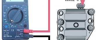
You can replace the switch with a known good one, you can evaluate its serviceability using a voltmeter. Turn on the ignition and look at the voltmeter. If the switch is working properly, the arrow will first deviate by a small angle (for 2-3 seconds), and then take its normal position. If it is faulty, the voltmeter needle moves to the maximum value immediately, without a pause. Read more: “Checking the switch of VAZ 2108, 2109, 21099 cars.”
Hall sensor check
The check can be carried out by replacing the sensor with a known good one or using a voltmeter (multimeter, autotester operating in voltmeter mode). The device must be connected to the green and black and white wires going to the sensor. To do this, you need to pierce the wires with two pins and connect a voltmeter to them. Slowly turning the crankshaft with the ignition on, observe the instrument readings. If the Hall sensor is working properly, then the voltage will jump from 0.4 V to the maximum voltage in the on-board network. We replace the faulty sensor; it cannot be repaired.
Checking high-voltage wires (armored wires)
Visually inspect the wires. We clean the dirt with a rag soaked in acetone. We definitely reject those that are burnt out inside. Using a multimeter or autotester (in ohmmeter mode), we check the resistance of each high-voltage wire. For working wires it is 3.5 - 10 kOhm. If at least one wire is faulty, it is advisable to replace not only it, but the entire set. Read more: “Checking high-voltage wires of VAZ 2108, 2109, 231099 cars.”
Checking the spark plugs
Checking the spark plugs for the presence of a spark is described above in the general check of the ignition system. The presence of a spark between the electrodes of the spark plug is an indicator of its serviceability. You can also check the serviceability of the spark plugs with a special probe. When conducting such a test, read the instructions for your probe and follow them.
It is also necessary to visually assess the condition of the candles. For example, the presence of black carbon deposits indicates either a malfunction of the spark plug itself, or a discrepancy between its heat rating and the required heat rating for a given engine, or a malfunction of the engine, etc. Read more about problems with spark plugs on the “Spark plug malfunctions” page.
Checking the ignition coil
The presence of a spark between the electrodes of the spark plugs indicates that the coil (“bobbin”) is working properly. More accurately, the degree of its serviceability can be determined using a multimeter, autotester and similar devices operating in ohmmeter mode. Remove the ignition coil. We connect an ohmmeter with one probe to terminal “B” of the coil, and with the second probe to terminal “K”. So we will check the resistance of its primary winding. It should be close to zero 0.4 - 0.5 Ohm. Next, again, one probe to terminal “B”, and the second to the terminal of the central armored wire. So we will check the resistance of the secondary (high-voltage) winding. It should be 4.5 - 5.5 Ohms. Then one probe to terminal “B”, and the second to the coil body. This is how insulation resistance is measured. It is equal to 50 MOhm. In addition to this check, we visually inspect the ignition coil, checking for cracks and burns on its cover. We clean it of dirt. We replace the faulty coil.
Switch design and malfunctions
The VAZ 2109 switch is one of the key elements of the car’s ignition system. The device is designed to switch current pulses of the required amplitude and duration in the primary winding of the ignition coil, depending on the control pulses of the Hall sensor. It also stabilizes the current from 6 to 18 V, protects semiconductors from overloads and ensures that the ignition system is turned off when the engine is stopped.
The housing provides a connection to ground through a radiator. When the device operates, a significant amount of heat is generated through its radiator. During operation, the radiator should be regularly cleaned of all kinds of contaminants to maintain heat transfer.
Signs of a faulty switch may include the following:
- when the starter is turned on, the engine does not start, there is no spark at the spark plugs;
- the engine starts, but soon stalls at idle;
- The engine runs unsteadily and the spark sometimes disappears.
A malfunction of the VAZ switch is not the only possible reason for the appearance of such symptoms. Such signs can be observed when the distributor fails or contact is lost.
To carry out repairs correctly, a thorough diagnosis is necessary.
Answers from experts
murzik99rus:
A switch is a device for matching something with something. A reel is a device with windings. By the way, the winch also has a reel.
Vladimir Bulanov:
the commutator supplies an impulse to the coil, the coil to the distributor and spark plugs
NN:
The coil is round with one thick wire and two thin ones, and the switch is square, aluminum, and many wires fit into it.
Ruslan:
A classic coil is an ordinary transformer with two windings: the primary winding works with the commutator and the secondary (boost) winding works with the spark plugs. A commutator is a device that, at the right moments, switches the current in the primary circuit of the ignition coil.
BL@cK13:
coil - creates high voltage commutator - designed to control the current of the primary winding(s) of the ignition coil
Alexander Kulikov:
On the ZIL 130, the switch is located on the left near the clutch pedal, and the coil, also known as the “bobbin” under the hood, is a cylindrical device topped with a truncated cone, from which protrudes a high-voltage wire that goes to the ignition distributor, colloquially a “distributor”
Denis Karpov:
A switch is an electronic device that controls the signal supplied to it. In a car, the switch controls the ignition coil using signals (pulses) that it receives from the sensor - the ignition distributor. The ignition coil is a step-up transformer, which turns 12 volts of the on-board network into 10,000 volts for the spark plugs. But since this is a transformer (converter), then the current in it must be either pulsed or alternating. The switch is responsible for the impulses.
Konstantin Salifov:
Switch is a device that distributes the spark supply torque among the cylinders. (Digital analogue of a trampler). The high-voltage coil significantly increases the voltage supplied to the spark plugs. The generator does not produce enough voltage to form a spark; a coil is needed for this.
Observer:
A switch is a device with which you can perform switching, that is, switching some incoming sources... For example: a telephone switch for 100 subscribers, a video switch, a microphone switch, etc.
Alexey Lobanov:
This relay is responsible for charging
Alexey Gerasimov:
SWITCH (from Latin commuto - I change) - an electromechanical, electronic or electron beam device (switch, switch, distributor) that provides selection of the required output electrical circuit and connection of the input circuit to it. The selection is made manually or automatically. The simplest electromechanical switches are switches, sets of electromagnetic relays, electromechanical finders. The switch is included in more complex devices, e.g. telephone exchange.
dixi2006:
A device (switch, distributor) that provides, by turning on, turning off and switching, the selection of the required output circuit (circuits) and the connection of the input circuit (circuits) with it,
ROMAN TISHAKOV:
Yuri Bulany:
The commutator in the auto-Hall sensor caught the window, generated a low-current signal, this signal went to the commutator, it amplified it in current, fed it to the coil, the coil - one end constantly sits during ignition (let's say +), the second end (minus) came from the commutator , there was a spark. That is, the switch is a current signal amplifier for the coil.
Andrey Lashch*****:
This is a rectangular piece of shit to which wires go with the magneto and from which they go to the coil and headlights
Diagnostics of device health
It is recommended to carry out in-depth diagnostics of the device at a specialized service. A professional stand will allow you to evaluate the condition of the unit in various engine operating modes in the range from 0 to 8000 rpm. The manufacturer categorically does not recommend diagnosing using artisanal methods. This is dangerous not only for the car’s electrical system, but also for the person trying to carry out such diagnostics.
If the car’s dashboard is equipped with a voltmeter, and the car owner knows how to check the VAZ switch, then a simple way is available to him to preliminary assess the performance of the device. One of the functions of the switch is to turn off the power to the ignition coil when the engine is not running but the ignition is on. With such a shutdown, the voltage in the on-board network increases noticeably. This means that to check the functionality of the device, you should insert the key into the lock, turn it to the ignition position, but do not turn the starter. At this time, you must carefully monitor the readings on the voltmeter.
In the first seconds, the arrow will freeze approximately in the middle of the scale, and after 8-10 seconds it will noticeably move to the right. Since the device worked, the coil turned off, the voltage increased, and the voltmeter responded, then everything is in order. If a switch fails, it usually happens entirely. It is unlikely that the secondary function remained operational, but the basic one failed. So, with a high probability, the device can be considered working.
UAZ won't start? No spark?
There can be a great many reasons.
But if you have already checked the flow of gasoline into the carburetor, and from there into the engine, then most likely the problem is in the ignition system. The UAZ 469 is an extremely simple car and no complex electronic components start this engine. An old, harsh distributor and a non-electric fuel pump. That's all that runs the old 417 engine.
Let's look at one of the common problems with the ignition of the UAZ 469.
The old UAZ has this problem, the switch is in the passenger's feet.
If you haven't changed it yet, then most likely you will have to replace it soon. Or someone else has already changed it before you.
My 1991 car has had this switch since the factory.
Alternative diagnostic methods
When there is no voltmeter on the dashboard, you can get out of the situation by doing everything yourself. To do this, you will need a 12 V light bulb and two meter wires with stripped ends. The diagnostic work flow diagram is as follows:
- disconnect the battery, de-energize the electrical system;
- using a size 8 wrench, unscrew the nut and remove the wire from the ignition coil terminal marked “K”, this wire is brown and goes to the clamp marked “1” on the switch;
- connect this wire to one of the test lamp wires;
- Connect the other wire of the control lamp to terminal “K” on the ignition coil;
- connect the battery;
- Turn on the engine starter and observe the condition of the lamp. If the lamp is flashing, the device is working properly. If the lamp does not light, the device is faulty.
There is another simple and reliable way to identify a device malfunction. To do this, you need to install a known-good switch, start the car and check the functionality of the system in all modes. If the system is working normally, then the problem was precisely the failure of this device, and when the same failures occur, the switch has nothing to do with it.
The disadvantage of this method is that you need to have a spare working switch with you. While this is reasonable for long journeys in uncrowded areas, it is exotic for regular city trips.
High voltage magneto
Starting engines installed on diesel engines have an autonomous high-voltage source - a magneto, which generates a low-voltage current, converts it into a high-voltage current and supplies it at a certain moment to the spark plugs.
The main magneto malfunctions are:
- rotor demagnetization
- damage to transformer windings
- breaker contact wear
- crack in parts of current-carrying devices
- capacitor breakdown
- violation of the magneto contour angle
The magnetization of the rotor is checked with an MD-4 magnetometer. If it is below 220 μWb, then the rotor is magnetized on the NA-5-VIM device from a 12-volt battery by turning on the device 2-3 times for 1-2 s.
The performance of the transformer is checked on the KI-968 stand with a current of 1.5-2.5 A, which is passed through its primary winding and the stand breaker. At a rotation speed of the breaker cam shaft of 500 min-1, a stable blue spark should appear on the three-electrode spark gap of the stand. The faulty transformer is replaced.
When the magneto is assembled, the rotor should rotate smoothly by hand and self-align into the neutral position, being moved away from it at an angle of 15-20°. Longitudinal movement of the rotor is allowed up to 0.06 mm. The gap between the open contacts of the breaker should be within 0.25-0.35 mm. The spring pressure at the moment of opening the contacts is 5-7 N. The outline is checked on the assembled magneto - the angle between the neutral position of the rotor (the rotor magnets are in a vertical plane) and the position of the rotor when there is a maximum current in the primary winding of the transformer; at this moment the breaker contacts should open. The outline size should be 8-12°. Violation of the outline setting leads to a decrease or complete cessation of sparking due to a decrease in the current in the primary winding of the transformer and the voltage in the secondary. To check the magnitude of the magneto outline, install it on the KI-968 stand, connect it to the drive, set the rotor to the neutral position, and rotate the arrester pointer to zero. Smoothly turning the magneto drive by hand in the direction of operating rotation, record the moment of opening of the breaker contacts (use the stand's IUC device or a test lamp). The outline is determined using the spark gap scale. Set the outline by turning the cam on the rotor neck.
The assembled magneto is tested for uninterrupted spark formation at a rotation speed of 2000-4500 min-1 for 5 minutes with a gap of 7 mm on the spark gap. The high-voltage insulation of the magneto is checked at a rotation speed of 2400-3000 min-1 and a gap on the spark gap of 9-11 mm for 15 s. During the test, sparking must be uninterrupted.
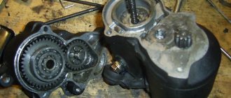
Features of repairing the VAZ 2109 switch
Repairing a switch most often comes down to replacing it. Fine-tuning the device is intended only to improve the efficiency of the system. If the device breaks down, the procedure for replacing it is as follows:
- de-energize the vehicle's electrical system, remove the main terminal from the battery;
- disconnect the brown wire from the negative terminal of the battery;
- Use a screwdriver to press out the spring bracket and disconnect the block with wires from the switch;
- unscrew the two radiator mounting nuts and remove the device together with the radiator;
- install a new switch with a radiator;
- connect the connector block;
- place the brown wire under the left nut;
- secure the switch to the VAZ 2109 with nuts;
- connect the battery.
What is and what is the principle of operation of the ignition switch
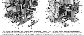
Even on the very first cars, battery ignition systems were used to ignite the combustible mixture, the functional diagram of which is shown in the figure.
This figure allows you to understand that its work is based on the principle of self-induction. When the current flow circuit in the winding of bobbin 3 is broken, a high-voltage EMF is induced in the secondary, causing a spark to appear on the contacts of spark plug 2. The circuit break is caused by the opening of the contacts of breaker 6.
Without touching on the advantages or disadvantages, it should be noted that this scheme worked on the car for a long time. And only the emergence of a new element base gave impetus to the further development of such a device, preserving the original principle of its operation.
What is port recycling?
Network communication channel utilization is the percentage of time during which a communication channel transmits signals, or otherwise, the proportion of communication channel capacity occupied by frames, collisions and interference.
Interesting materials:
What should be included in the conclusion of the project? What should a court decision contain? What do beneficial bacteria eat? What is in the lithosphere? What's in Vegas? What kind of Viber program is this? What develops during adolescence? What is the penalty for using other people's photographs? What was one of the reasons for the defeat of whites in the Civil War? What is fard in prayer?
What could the ignition system switch look like?
The above switch circuit is just one of the options for how the ignition device can be implemented. This is done using:
- transistors;
- thyristors:
- hybrid elements;
- contactless sensors.
The transistor circuit of the switch is discussed above; the thyristor circuit uses energy accumulation in the capacitor, and not in the electromagnetic field of the ignition coil. During operation of the thyristor system, when control signals are received, the circuit connects a charged capacitor to the windings of the coil, through which it is discharged, causing a spark to appear. Without touching on the advantages and disadvantages that this or that circuit has, suffice it to say that any such device provides a significant improvement in all parameters of the ignition system, and the switch over time has replaced conventional battery ignition.
However, it is necessary to note one more stage in the development of the system, and the switch in particular. The use of electronic components and the introduction of a switch into the design of the car made it possible over time to abandon the contact voltage breaker and replace it with a contactless sensor. Such a system, in domestic cars, was first used in VAZ cars, in particular the VAZ 2108. A similar operating principle, when the switch receives signals from a special unit, is implemented on the VAZ 2108 using a Hall sensor.
When considering the options for what the switch device could be, one cannot ignore the development of the ignition system itself. The main principle that is implemented during its construction is to increase the reliability and efficiency of the entire system. This is achieved by using microprocessor systems that use the readings of numerous sensors. To work with such systems, you need at least a two-channel switch, and recently a separate coil and switch for each spark plug. This approach – a two-channel switch (later also multi-channel) allows you to provide:
- more powerful spark;
- elimination of losses in the distributor;
- stable idle;
- improved starting at low temperatures;
- reduction in fuel consumption.
Breaker-distributor
The main faults are:
- wear and burning of contacts
- decrease in spring elasticity
- wear of the textolite bushing and heel of the breaker lever
- cracks or through spark breakdown of parts (cover, rotor)
Burnt contacts are cleaned with glass sandpaper or a special needle file, followed by wiping with a rag soaked in gasoline. If the contact height is less than 0.6 mm, replace the breaker lever or contact stand assembly. Instead of worn contacts, new ones are soldered using PSr-70 solder.
The spring tension is checked using a dynamometer. The spring force along the axis of the contacts at the moment of their rupture must be at least 4.9 N. The moment of contact rupture is determined by a test lamp. If the spring weakens, the breaker lever assembly is replaced.
In ignition timing regulators, damaged springs, diaphragms, fitting gaskets, and textolite parts are replaced with new ones.
In the assembled breaker-distributor, the roller should rotate easily, its longitudinal movement should not exceed 0.25 mm. The assembled breaker-distributor is adjusted and tested on the KI-968 stand. It is connected to the induction coil and battery of the stand. The average value of the current passing through the contacts of the breaker, other things being equal, depends on the angle of the closed state of the contacts, i.e., on the angle of rotation of the breaker cam, within which the contacts are in the closed state. At the stand it is controlled using the IUC device. The angle is checked at a cam rotation speed of 1500 rpm and adjusted by changing the gap between the contacts.
How to determine if the ignition switch is faulty
The introduction of an ignition switch into the design of a car, especially on domestic cars of the VAZ family, made it possible to increase their reliability. And although the first production car with an electronic ignition system was the VAZ 2108, similar devices began to be installed on many other cars, primarily classics. However, the use of such a rather complex product has led to the fact that finding a malfunction, as well as checking and repairing the switch, has become possible for the most part only in specialized centers. External signs indicating that a malfunction has occurred may include:
- the engine does not start, there is no spark at the spark plugs;
- the engine starts but stalls after a few minutes;
- The motor is unstable; if the switch is replaced with a known good one, the defect is eliminated.
The easiest way to identify a malfunction and test a switch, as already noted, is to install a known-good one. Due to the rather low quality of the switches supplied for the VAZ family of cars, including the VAZ 2108, drivers have to carry additional switches with them to replace the failed one. However, there is also an indirect evaluation principle that allows you to check the performance of the product and identify its malfunction.
To do this, you can use the readings of the voltmeter in the instrument cluster. You need to turn on the ignition, and the needle will be in the middle of the scale, and a little later it will swing to the right (due to the power supply to the coil being turned off when the engine is not running). This arrow behavior indicates that there is no fault in the switch. In the event that there is no voltmeter, a test lamp is required to check the ignition. One end of it is connected to ground, the other to the output of the coil connected to terminal 1 of the switch. If you turn on the ignition, then if the switch is working properly, after a while the lamp will burn brighter.
However, in some cases, the ignition malfunction is not related to a switch failure. It is necessary to check the condition of the wires, first of all, contact with ground and the condition of the connectors. It is also necessary to check the Hall sensor.
The appearance of a voltage switch in the design of a car, including the domestic VAZ 2108, was a natural result of the development of the ignition system. Its further improvement was the use of first dual-channel and then multi-channel switches to improve operating efficiency. » alt=»»>
Checking the 2109 switch yourself on a VAZ, or simply “nine” car is something that sooner or later every owner of this domestic car may encounter.
This small electrical device, if it fails, makes operating the car difficult or even impossible.
In our material we will analyze in detail: what is this switch, why is it needed and how to determine whether it is working?
Content:
Price
More details in the table.
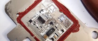
And finally, remember that when replacing a powerful switching transistor, it is important to pay attention to the quality of fixation of the part to the switch body. Many beginners make mistakes here or do not apply enough heat-conducting paste. As a result, the device cannot be repaired.
A characteristic feature of the car can be considered its rapid obsolescence, but long life. The most modern car today, in at least two years, will be inferior to other, newer cars with improved characteristics. But even now there are cars from the last century on the roads. Therefore, it is not just interesting, but sometimes necessary, to know at least in general terms what such vehicles are, their structure, features, including such a thing as a simple ignition switch, which significantly changed the capabilities of the car.
The switch is the basis for uninterrupted engine operation
The VAZ 2109 car is equipped with a contactless ignition system.
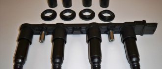
The system includes spark plugs, four high-voltage wires (one for each spark plug), a Hall sensor, a distributor, an ignition coil and, in fact, a switch.
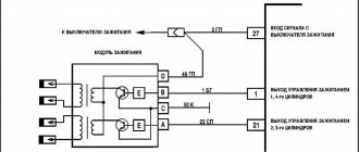
Rice. 1 Ignition circuit of VAZ 2109 Schematic illustration.
The ignition system generates an electrical impulse (spark), thereby igniting the mixture of fuel and air in the combustion chambers necessary for engine operation.
The switch is responsible for the cyclic supply of pulses to the ignition coil, this is necessary for the proper operation of the entire system as a whole.
Thus, if the switch is faulty, the spark will supply intermittently or be completely absent. It is not possible to drive such a car.
The VAZ 2109 switch itself consists of an aluminum case and a microcircuit installed on it. The device is mounted in the engine compartment and connected by wires to the ignition coil.
Rice. 2 Appearance of the VAZ 2109 switch.
The design of the housing and the mounting method allow the switch to successfully withstand vibrations that occur when the car is moving.
The VAZ 2109 contactless ignition system switch has the following performance characteristics:
- Voltage range 6–16 Volts.
- Operating voltage 13.5 Volts.
- Switching current 7.5–8.5 Amperes.
- A switch in good condition ensures an uninterrupted supply of spark to the cylinders with a crankshaft speed of up to 7000 rpm.
Active forum discussions
What problems with the spark plugs are you talking about? When connecting the coil to the car’s ignition system, in principle, you should not have any difficulties if, during preliminary dismantling, you marked or remembered which wires are connected where.
The rotor is a ring permanent magnet with four-pole cages tightly pressed to it from above and below, rigidly fixed to the sleeve. To do this, you can use an indicator screwdriver.
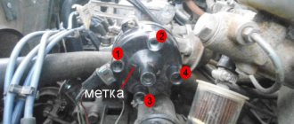
People who are too lazy to read the Kama Sutra and think with their heads often ask the question: “Then why is there a mark on the crankshaft pulley, if not for a strobe light? Switch The switch is designed to provide a powerful impulse regardless of engine crankshaft speed, thereby facilitating ignition of the fuel mixture. The capacitor in the breaker is no longer needed; it can be turned off - one less weak point.
Double switches are available for all systems: with a variator, without a variator and with a Hall sensor. People who are too lazy to read the Kama Sutra and think with their heads often ask the question: “Then why is there a mark on the crankshaft pulley, if not for a strobe light? Has one output. The rotor is a ring permanent magnet with four-pole cages tightly pressed to it from above and below, rigidly fixed to the sleeve. That's all. Checking the Hall sensor and switch: 1.
Ignition system
The unnamed terminal of the coil is connected to the short-circuit terminal of the commutator and the commutator to ground.
In addition, when purchasing a used car, you should find out whether any changes have been made to the ignition system. Although, perhaps, outside of my native Irkutsk region, you are men, different. The IT pulse transformer serves to speed up the turn-off of the transistor when the breaker contacts open. Return to contents Cost of replacing the ignition system As you can see, the GAS ignition system consists of many components. Therefore, when replacing or performing repairs, you must follow safety regulations. The stator has an insulated stranded lead connected to the sensor lead. The ignition coil is of a cylindrical type; in older ignition systems the BB model was used. Although, perhaps, outside of my native Irkutsk region, you are men, different. Photos GAZ Burnout of the distributor cover often occurs due to a loose connection of the central high-voltage wire with the distributor cover.
The IT pulse transformer serves to speed up the turn-off of the transistor when the breaker contacts open. Output terminal on the primary and secondary windings; Center terminal spring; External insulation on the primary winding; Mounting bracket; External magnetic circuit and core. The reason may also be hidden in the electrical wiring: in particular, due to a damaged wire running from the switch to the ignition coil. There is also an ignition coil B. As you noticed, it looks no different from B. Some people install it; it is also suitable for GAZ, but I personally do not advise you to install it. Electrical wiring for 270 rubles. Or how to start the engine without a scooter
Signs of a broken switch
During the operation of the car, unpleasant symptoms may occur, indicating a malfunction of the ignition system.
A possible reason for this may be incorrect operation of the switch. Here are the most common symptoms that should suggest a possible breakdown of this device:
- Can't start the engine. There is no spark when the starter is running.
- The engine starts and runs normally at low and medium speeds, but cannot be revved up at high speeds. The engine is not running at full power.
- The car stalls when moving away, although it idles stable.
- The engine starts, but does not run for a long time and immediately stalls.
- The engine begins to operate unstably - “triple”, reaching a certain speed level. When cold it can start quite normally.
- The engine may periodically, without any pattern, stall, then work normally again. The battery discharge indicator lights up. The tachometer needle shows sharp changes in the number of revolutions.
Verifying switch operation
Every car enthusiast with a sufficient level of desire and minimal technical skills can check the operation of the switch.
The easiest way to check is to replace the unit with a new one that is known to be good. If after this the problems in the engine operation have disappeared, then we can conclude that the old switch has already served its purpose.
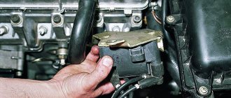
Every car enthusiast can replace the switch independently. First of all, you need to find it under the hood of the car.
The switch is located in the area of the left (driver's) pillar. It is connected by wires to the coil.
Rice. 3 Engine and organization of the engine compartment of the VAZ 2109.
1 – front glass of the shock-absorbing strut; 2 – water tank; 3 – air filter; 4 – fuel pump; 5 – steering rack; 6 – camshaft sensor; 7 – vacuum brake booster device; 8 – master cylinder of the brake system and its barrel; 9 – switch; 10 – fuses; 11 – engine cooling system tank; 12 – battery; 13 – hood fastening; 14 – ignition coil; 15 – starter; 16 – high-voltage wires; 17 – neck for oil; 18 – engine; 19 – candles; 20 – windshield washer system.
Next, disconnect the negative terminal from the battery. Then you should carefully disconnect the plastic bracket with wires from the switch. To do this, you need to release the spring clip.
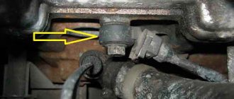
Then we unscrew the nuts that secure the aluminum switch housing to the car body. Under the left nut there will be a ground terminal.
Remove the switch from the studs and replace it with a new one. The new one is installed in the reverse order.