As a rule, they select the types of jets for the Solex 21073 carburetor while adjusting it on the engine. Some drivers sometimes think that if a dream has come true, and Solex is finally installed on the car, then all problems will be resolved at once. But it was not there! The main work only begins after installation. Solex, designed to save you money on fuel resources, in order for it to function correctly, it also needs to be finely tuned.
It’s good if you know a carburetor mechanic. And if not? You can try to make the adjustment yourself, but for this procedure you need to know at least more information about the carburetor itself.
Selecting the types of jets for the Solex 21073 carburetor is one of the components of its configuration for the most reasonable further operation. And before replacing one with another, you need to fundamentally understand: why, and what kind of detail is this?
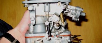
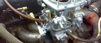
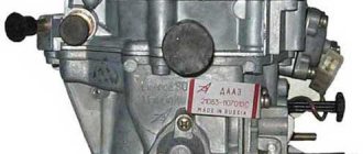
Carburetor DAAZ 21073 - device
The device of the Dimitrovgrad Automotive Aggregate Plant is designed for mixing fuel and air and consists of two main components:
- Frame;
- Top cover.
The device is also based on a float chamber for balancing the level of fuel supplied to the diffuser, an accelerator pump, a forced idle economizer and an econostat. The top cover contains: an emulsion tube or emulsion wells, fittings designed for atomizing fuel in the diffuser, as well as an air damper necessary for cold starting of the power unit. The Solex 21073 carburetor on the Niva is installed and configured from the factory, and its design and calibration data provide good dynamic performance with minimal fuel consumption.
Calibration data
| Name | 21073 stock | 21073 mine | 21053-*** | 21053- | ***-20 | |||
| 1st camera | 2nd camera | 1st camera | 2nd camera | 1st camera | 2nd camera | 1st camera | 2nd camera | |
| Engine capacity | 1700 | 1500 | 1500 | 1600 | ||||
| Main diffuser | 24 | 24 | 24 | 24 | 23 | 24 | 23 | 24 |
| gtzh | 107,5 | 115 | 115 | 115 | 102,5 | 115 | 107,5 | 110 |
| GVZh | 150 | 135 | 150 | 135 | 150 | 135 | 140 | 165 |
| TJ XX and move on. System 1 | 39 | — | 42 | — | 39 | — | 40 | — |
| TJUN | 45 | — | 35 | 40 | 35 | 40 | 45 | 40 |
| Kulachek UN | 4 | 7 | 4 | 5 | ||||
| TJ EMR | 40 | — | 40 | — | 40 | — | 40 | — |
| Choke cam | 6 | — | 6 | — | 7 | — | 3 | — |
| T/W ratio | 0,717 | 0,852 | 0,767 | 0,852 | 0,683 | 0,852 | 0,768 | 0,667 |
| Total t/v ratio | 0,781 | 0,807 | 0,763 | 0,713 | ||||
Carburetor calibration data 21073-1107010 | ||
| Options | first camera | second camera |
| Mixing chamber diameter, mm | 32 | 32 |
| Diffuser diameter, mm | 24 | 24 |
| Main dosing system: fuel jet marking air jet marking | 107,5 117,5 | 150 135 |
| Emulsion tube type | ZD | ZC |
| Idle system and transition system of the first chamber: fuel jet marking air jet marking | 39 140 | |
| Second chamber transition system: fuel jet marking air jet marking | — — | 70 140 |
| Power mode economizer: | — | 70 |
| Econostat: conditional fuel jet flow rate fuel jet marking spring compression force at a length of 9.5 mm, N | — 40 1,5±10% | — |
| Accelerator pump: nozzle marking, fuel supply in 10 cycles. sm3 cam marking | 14 — 4 | — — |
| Starting clearances: air damper, mm throttle, mm | 3,0 | — |
| Marking of the choke control lever | 6 | — |
| Hole diameter for vacuum corrector, mm | 1,2 | 1,2 |
| Needle valve hole diameter, mm | 1,8 | 1,8 |
| Diameter of the fuel bypass hole into the tank, mm | 0,70 | 0,70 |
| Engine crankcase ventilation hole diameter, mm | 1,5 | — |
Scheme and principle of operation
The types and modifications of carburetors for a given car can be very different, but the principle of operation remains the same.
When starting the engine cold, the driver closes the choke to limit the flow of air and increase the amount of gasoline. This makes it easier to start and brings the speed necessary for stable operation.
Carburetor 21073 DaAZ device and principle of operation: diagram of the design and operation of the carburetor I - first chamber; II - second chamber; 1 — accelerator pump drive lever; 2 — adjusting screw of the starting device: 3 — diaphragm of the starting device; 4 — air channel of the starting device; 5 - solenoid shut-off valve; 6 — idle fuel jet; 7 — main air jet of the first chamber; 8 — idle air jet; 9 — air damper; 10 — sprayer of the main dosing system of the first chamber; 11 — accelerator pump nozzle; 12 — nozzle of the main dosing system of the second chamber: 13 — econostat nozzle: 14 — main air jet of the second chamber; 15 — air jet of the transition system of the second chamber; 16 — channel for balancing the float chamber; 17 - float chamber; 18 — needle valve; 19 — calibrated hole for fuel bypass into the tank; 20 — carburetor fuel filter; 21 — fuel supply fitting; 22 — power mode economizer diaphragm; 23 - fuel jet of the power mode economizer; 24 — ball valve of the power mode economizer; 25 - float; 26 — econostat fuel jet with tube; 27 — fuel nozzle of the transition system of the second chamber with a tube; 28 — emulsion tube of the second chamber: 29 — main fuel jet of the second chamber; 30 - outlet of the transition system of the second chamber; 31, 33 — throttle valves: 32 — slit of the transition system of the first chamber; 34 — outlet of the idle system; 35 — carburetor heating block; 30 - adjusting screw for the composition {quality} of the idle mixture; 37 — engine crankcase ventilation fitting; 38 - fitting for supplying vacuum to the vacuum ignition regulator; 39 — vacuum selection fittings for the recirculation system; 40 — main fuel jet of the first chamber; 41 — emulsion tube of the first chamber; 42 - ball valve of the accelerator pump; 43 — accelerator pump diaphragm.
During the warm-up process, air intake is increased to reduce speed and eliminate interruptions. Thus, the air damper opens completely and the amount of gasoline is reduced. Other methods of warming up are not provided for by the design.
Gasoline is supplied through the fuel filter to the float chamber, and then to the main metering system of the mixing chamber. The scheme for pumping air and mixing it with gasoline in the diffuser occurs due to the vacuum that occurs during the operation of the valve mechanism and pistons, compressing and pushing out the working mixture.
The second chamber system is designed to increase air flow to the nozzle when the engine is running under heavy load, when the speed is high.
To ensure that the engine runs stably at idle, and at low speeds to prevent it from stalling and eliminate interruptions, an idle system is provided. And to maintain the level of fuel used in the Solex 21073 carburetor, there is a whole scheme for the operation of the float system. Let's consider the operation of each system separately.
Solex carburetor float chamber
The float mechanism is located in the top cover of the carburetor and serves to maintain the required level of fuel, which is supplied to the metering chamber.
He is:
- Small cavity;
- Ebonite float;
- Needle valve.
The calibration data for the Solex DAAZ 21073 carburetor provides for the following operating principle of the float chamber. When the fuel level decreases, the float lowers and with its lever opens the needle valve at the top of the cover. Through the resulting hole, gasoline enters the chamber and fills it, raising the float up. As soon as the float rises completely, the valve closes and the cycle repeats throughout engine operation.
Adjusting and adjusting the level of the float chamber affects the dynamic performance of the motor. If the level is insufficient, the power plant does not operate stably, and if it is too high, fuel consumption increases and the spark plugs fail.
Main dosing chamber - operating principle
During engine operation, the cylinders create a vacuum, which draws air from the air filter and supplies it to the diffusers - these are the main metering systems. After this, all the oxygen leaves through the cross-section of the damper of the first chamber and the jets of the Solex 21073 carburetor. Thanks to the throttle jets of the second chamber and the reduced diameter of the diffuser of the first chamber, the air flow speed increases, and in the spray zone it reaches maximum values.
Subsequently, after passing through the air jet of the throttle valve of the first chamber, the air is mixed with fuel and sucked into the channels of the intake manifold, which distributes the mass of the fuel mixture among the engine cylinders. To increase efficiency, distribution occurs in those cylinders where the intake valve is open and there is the required vacuum. This principle of operation ensures a reduction in fuel consumption and the elimination of contamination of the timing belt.
Selection Basics
If we install, for example, Solex 21041 (volume 1.8) on a 1.5 engine. This carburetor has a 24x26 diffuser, fuel volume is 102.5, which is not enough for a 1.5 engine. We are looking for a match between the chambers and the diffuser. We find the closest option: Solex 21073. It has a 24x24 diffuser and a TJ - 107.5. And the first cameras are almost identical. By the way, if the diffusers are almost the same, and the engine volume is smaller, then the intake of gasoline will be less (the jet is rather poor). This means that we need fuel jets (fuel jets) from 110. Let’s get a few.
Next you need to decide
, what do you want to get: economical slowness or costly acceleration. Depending on the decision, we also select a fuel mixture: to adjust the enrichment or leanness of the air-fuel mixture (a lean mixture will lead to gasoline savings, but will affect the acceleration dynamics of the car).
Idle system
In some situations, engine operation must be ensured even when the car is in neutral, when the speed is too low. At such a moment, the vacuum is insufficient and fuel will not be able to pass through the main metering chamber. A forced idle system is provided specifically for this purpose.
To do this, air is supplied through the main idle fuel jet into the first chamber. The fuel will then flow to the idle fuel jet. The air also passes through a special jet through a separate channel. This design allows the engine to operate even at low speeds, and when the throttle valve is opened, the power mode economizer begins working, which is considered as a transition system.
However, the system has a number of disadvantages when coasting:
- When the speed decreases by releasing the gas, fuel consumption continues;
- When switching to neutral gear, it increases completely.
Especially for this purpose, the calibration data also includes an EPHH, which turns off the fuel supply when coasting. Its operation continues until the speed drops to 1200 rpm and turns off when the throttle is opened. But when the car is stationary, it does not work.
His Majesty diffuser
As you can see, the diffuser occupies not the last place in this hierarchy, and here’s why. The main problem with Solex DAAZ 21083 is that the standard mixture is too lean. The engineers deliberately took this step in order to strangle the engine in favor of efficiency, depriving it of its dynamic potential. But even without resorting to complex and subtle calculations, it is clear that first of all it is necessary to eliminate aerodynamic errors, which are full of any DAAZ carburetor.
After the diffusers are brought into human form, the filling of the cylinder with the working mixture is significantly improved, and as a result, the output from the engine, even after such an insignificant alteration at first glance, is visible even to the eye. Now it makes sense to think about increasing the filling of the combustion chamber. Standard diffusers on 21083 have diameters of 21x23 mm of the primary and secondary chambers, respectively. Usually the dimensions are adjusted to 24 mm, so the motor will not be pinched at least by air.
Now you can increase the diameters of the fuel jets. “Can” does not mean necessary, and if fuel economy is more important, then the jets are best left alone. Even after replacing them with jets of increased diameter, the car will not turn into a Maserati, but fuel consumption will definitely increase. If this doesn’t scare you, then change the standard jets to 107.5 and 115, and the air jets to 155 and 135 in the primary and secondary chambers, respectively. If you are not satisfied with the result, you can always install the standard jets in place.
Troubleshooting - Solex carburetor 21073
The Solex carburetor 21073 was installed on the Niva 21213 for quite a long time, after which repairs and adjustments are quite common.
Therefore, the following malfunctions cannot be excluded:
- Higher fuel consumption;
- Poor starting qualities;
- Power reduction;
- Unstable engine operation at idle.
The main malfunctions during carburetor operation originate from low-quality fuel, which has foreign particles. They are the main reasons that clog the jets and channels, leading to malfunction of the device. The installed carburetor 21073 1107010 DAAZ on Niva has a device in which the jets are most susceptible to contamination. Therefore, diagnosis must begin with them.
Content
The engine sucks air through the diffuser, and a certain amount of gasoline through the fuel nozzle. The volume of air and fuel sucked in depends on the volume of the engine. Therefore, the trend is to install a small jet for a larger engine volume. And if you have to install a similar Solex 21073 carburetor on a small engine (for example, 1.5), then the standard jets are poor (that is, they give an unsaturated mixture).
Therefore, we can say that it all starts with the fuel nozzle - its selection and settings. Afterwards, for the second time, you need to pick up an air one for it. Start strictly with the first camera until you have set it up; it is not recommended to work on the second one under any circumstances.
Rule:
We select the jets according to the engine volume. And before starting the setup, it’s best to find a factory Solex that matches the volume of the unit on your car, and rearrange (or install the same) jets from it.
Repair and maintenance of the Solex 21073 carburetor in the field
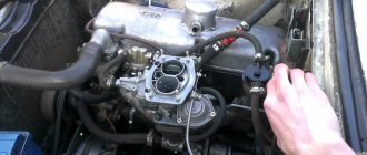
To repair the carburetor, you must remove it from the engine. To do this, first of all, remove the air filter, all hoses going to the device, rods and throttle valve drive, and then it is removed.
Before disassembling, it is recommended to obtain a repair kit to troubleshoot the carburetor, which includes:
- Gaskets;
- Jets;
- Needle valve;
- A set of rods and small fasteners.
It is recommended to disassemble the carb on a large table and lay out the parts in order so as not to lose them during work. Repair of the Solex 21073 carburetor on a Niva car is carried out in the following sequence - disassembly, washing of all parts with a special liquid, installation of parts from the repair kit and assembly. The types of repair kits differ depending on the model of the device.
Selection of jets is one of the most important procedures. The selection is made taking into account the technical data of the device and should be based on the personal choice of the car owner. It should be taken into account that increasing the cross-sectional diameter leads to improved dynamic characteristics and increases fuel consumption. Types of jets can be very different.
Therefore, if you select the jets correctly, you can achieve good performance with minimal gasoline consumption.
After installing the device on the car, the idle speed is adjusted. It will restore normal engine operation and reduce fuel consumption.
Replacement in every detail
Adjusting screws for the Solex carburetor 2108
Having selected the Solex carburetor jets by numbers, you can begin to replace them; unlike boring, it is quite possible to carry out this operation yourself at home. By the way, the reason is not always an incorrectly selected element; very often during operation, these parts wear out and become clogged, which leads to a change in the diameter and composition of the mixture with all the ensuing consequences. In addition, car owners in this way increase the power of their “iron horse” or, conversely, reduce gasoline consumption. In general, replacing jets is quite suitable in the category of vehicle tuning.
To remove the Solex jets, you will have to dismantle the engine and, of course, disassemble it. Before removing the power unit, be sure to disconnect the negative cable from the battery, and then remove the air filter housing. Prepare a clean rag and a solvent, such as white spirit, in advance to clean the surface of the motor from dirt. Now you need to find the place where the drive cable is attached to the air damper and slightly loosen the screw securing these parts. Do the same with the bolt securing the cable sheath. An open-end wrench is perfect for this purpose. After disconnecting the cable from the carburetor, remove the crankcase gas supply hose from the pipe.
Removing jets from Solex
To disconnect the fuel hose from the fitting, in addition to a wrench, you will also need a Phillips screwdriver. First, loosen the fastening clamp, then remove the hose and use an M8 bolt to plug the hole in the latter. It is necessary to remove the vacuum regulator hose. The wire terminal is also disconnected from the solenoid valve terminal. We take a flat-head screwdriver and use it to press out the end of the throttle linkage, and then remove it. Now it is possible to remove the return spring.
To remove the carburetor you need to prepare a spanner and open-end wrench set to “13”. The first to unscrew are 3 nuts, through which the part is attached to the inlet pipeline, and the second is the fastening nut. Take this opportunity to inspect the carburetor gasket; perhaps it could use replacement. If the unit will be removed for a long time, be sure to plug the inlet pipe with a rag. To replace the jets in the carburetor, it remains to remove the cover from it. Take a flathead screwdriver and unscrew these parts. First we remove the fuel jets, then the air jets. In the rings of the last parts you will find emulsion tubes; to pull them out, you should pry them off with a file.
Replacing the carburetor gasket
The main fuel element of the secondary chamber is designated by the letter “A”, and the primary one by “B”. Then we proceed to removing the air jets, marked “B” and “D” for the secondary and primary chambers, respectively.
Replacement should not be done blindly. Visually assess the condition of the jets. The presence of marks, scratches and irregularities on their inner surface is unacceptable, since these defects reduce throughput. Contamination of parts with resins also has a negative impact. Before installing new jets, it is advisable to check them on a special stand, so you can see how well the specified throughput of the elements corresponds to real indicators.
Installation of new Solex parts
If you have already started disassembling the carburetor, then it would be a good idea to study the condition of its other parts; perhaps replacing the jets is not the only need for this unit. We unscrew the accelerator pump screw and remove the latter along with the valve and o-rings. Then we remove the rings and diffusers of both chambers from their original location. To remove the channel from the accelerator pump, you need to unscrew the fixing screw.
Next, remove the fuel nozzle along with the housing and take it out. You can dismantle the diaphragm after you open its cover and remove the spring. Having unscrewed the bolted connections, we disconnect the carburetor body and the throttle valve. Now you have access to the thermal insulation element and cardboard spacers. Remove the cover along with the adjusting screw, then remove the latter with the sealing ring. All parts with defects must be replaced; the remaining parts are thoroughly washed in a special product. We blow out the jets and other holes with compressed air. Reassemble in reverse order.
Adjusting the Solex 21073 carburetor on Niva
Before starting the adjustment, it is necessary to insert a level in the float chamber so as not to disassemble the carburetor again. To do this, pump fuel using a hand pump and remove the top cover. If you pay attention, there is an inclined plane in the chamber, in the middle of which the fuel level should be located. If it is different, then it is set by bending the antennae of the float.
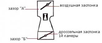
The next step is to adjust the air damper, starting gap and starting device. There is nothing complicated here. You need to pull out the choke completely and close the damper. In this state the cable is fixed. Now you need to test the operation of the damper: with the handle completely retracted, the damper should be open and vice versa.
Now the carburetor idle speed is adjusted (Solex 21073). To do this, you need to completely tighten the quality and quantity screws, and then unscrew the quality adjusting screw by four turns, and the quantity by three turns. After this, the engine is started and warmed up to operating temperature. After eliminating the interruptions, you can start setting up.
Tighten the quantity screw until the speed drops to 800-900 rpm. Now set the maximum speed by turning the quality screw. Tighten the quantity again to 800 rpm. Now we adjust the quality until the engine begins to shake slightly. This moment will be the most optimal.
There is another method, which involves repeating the first cycle until further adjustment is impossible. Both methods work, so you can adjust them in different ways.
If the carburetor does not work and is not adjustable, you should look for excess air leaking through the gaskets or check the timing belt and ignition. Resolve the problem and try again. To eliminate this problem, check the damper clearances.
The car must be parked on a level surface, and the low beams and main electrical consumers must be turned on. That's the only way to regulate it.