Switch design and malfunctions
The VAZ 2109 switch is one of the key elements of the car’s ignition system. The device is designed to switch current pulses of the required amplitude and duration in the primary winding of the ignition coil, depending on the control pulses of the Hall sensor. It also stabilizes the current from 6 to 18 V, protects semiconductors from overloads and ensures that the ignition system is turned off when the engine is stopped.
The housing provides a connection to ground through a radiator. When the device operates, a significant amount of heat is generated through its radiator. During operation, the radiator should be regularly cleaned of all kinds of contaminants to maintain heat transfer.
Signs of a faulty switch may include the following:
- when the starter is turned on, the engine does not start, there is no spark at the spark plugs;
- the engine starts, but soon stalls at idle;
- The engine runs unsteadily and the spark sometimes disappears.
A malfunction of the VAZ switch is not the only possible reason for the appearance of such symptoms. Such signs can be observed when the distributor fails or contact is lost.
To carry out repairs correctly, a thorough diagnosis is necessary.
VAZ models 8 and 16 valves
Despite the similarity in engine design, the ignition system of the 1.5-liter injection 16-valve engine differs from the 1.6 16-valve engine. The 1.6 liter engine uses an electronic contactless ignition system with individual coils on each spark plug. Therefore, there was no need for an ignition module. Such a system is more reliable and cheaper to operate, since if one coil fails, there is no need to replace the entire module.
The 16-valve 1.5-liter VAZ 2112 injection engine used the same non-contact ignition system as the 8-valve engine, but a different ignition module was installed. Its catalog number is 2112-3705010. The design of the module remains the same - two ignition coils (for cylinders 1-4 and 2-3) plus switch keys in a single block. The spark is supplied to the cylinders in pairs using the idle spark method. This means that sparking occurs in two cylinders simultaneously - in one on the compression stroke (working spark), in the second on the exhaust stroke (idle spark).
Diagnostics of device health
It is recommended to carry out in-depth diagnostics of the device at a specialized service. A professional stand will allow you to evaluate the condition of the unit in various engine operating modes in the range from 0 to 8000 rpm. The manufacturer categorically does not recommend diagnosing using artisanal methods. This is dangerous not only for the car’s electrical system, but also for the person trying to carry out such diagnostics.
If the car’s dashboard is equipped with a voltmeter, and the car owner knows how to check the VAZ switch, then a simple way is available to him to preliminary assess the performance of the device. One of the functions of the switch is to turn off the power to the ignition coil when the engine is not running but the ignition is on. With such a shutdown, the voltage in the on-board network increases noticeably. This means that to check the functionality of the device, you should insert the key into the lock, turn it to the ignition position, but do not turn the starter. At this time, you must carefully monitor the readings on the voltmeter.
In the first seconds, the arrow will freeze approximately in the middle of the scale, and after 8-10 seconds it will noticeably move to the right. Since the device worked, the coil turned off, the voltage increased, and the voltmeter responded, then everything is in order. If a switch fails, it usually happens entirely. It is unlikely that the secondary function remained operational, but the basic one failed. So, with a high probability, the device can be considered working.
Table: cost of switches
| Switch models | Price in rubles |
| Switch GAZ 131.3734 Rhombus | 400 |
| Transistor 1302.3734 | 450 |
| 133.3774 (analogue 3620.37740) VAZ 2108-099, Tavria (Energomash) (20) | 450 |
| Switch for cars VAZ 2108-2110, VAZ 2121 “SOATE” | 500 |
| 0529.3734 Vinnitsa VAZ 2121 - 21214 NIVA | 500 |
| 12.3774-01 (an.76.3774-02) ` Switch ZIL-130, -43410, AZ-53, PAZ, LIAZ, KAVZ (Energomash) | 600 |
| Energomash Switch VAZ-2108-10, 2121,1111 (96.3734,3620.3734,76.3734) (Energomash) with emergency mode and diagnostics | 700 |
| Switch GAZ 131.3734 SOATE | 700 |
| 131.3734 Switch Volga, GAZ, UAZ, IZH, ZIL-130, Moskvich, PAZ, KAVZ (SOATE) | 800 |
| Switch with modern electronic base for GAZ, UAZ "SOATE" vehicles | 850 |
| Ignition system switch TK-200-0 / TK-200-01-0 (analogous to BU931) | 1000 |
Alternative diagnostic methods
When there is no voltmeter on the dashboard, you can get out of the situation by doing everything yourself. To do this, you will need a 12 V light bulb and two meter wires with stripped ends. The diagnostic work flow diagram is as follows:
- disconnect the battery, de-energize the electrical system;
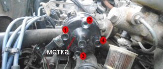
- using a size 8 wrench, unscrew the nut and remove the wire from the ignition coil terminal marked “K”, this wire is brown and goes to the clamp marked “1” on the switch;
- connect this wire to one of the test lamp wires;
- Connect the other wire of the control lamp to terminal “K” on the ignition coil;
- connect the battery;
- Turn on the engine starter and observe the condition of the lamp. If the lamp is flashing, the device is working properly. If the lamp does not light, the device is faulty.
There is another simple and reliable way to identify a device malfunction. To do this, you need to install a known-good switch, start the car and check the functionality of the system in all modes. If the system is working normally, then the problem was precisely the failure of this device, and when the same failures occur, the switch has nothing to do with it.
The disadvantage of this method is that you need to have a spare working switch with you. While this is reasonable for long journeys in uncrowded areas, it is exotic for regular city trips.
Scheme and principle of operation of BSZ
We connect a 12 V light bulb instead of the coil.
For an analogue of the foreign microcircuit LB, see
To have an idea of what this gadget looks like and what to look for, you can look at a photo of the switch on our Internet portal.
They have contacts that can burn or simply wear out. The controllers also control the electrovalve of the economizer of forced idling EPHH. The use of semiconductor and microprocessor switches in contact-transistor or contactless ignition systems allows you to obtain the following advantages: the current flowing through the breaker contacts is reduced, as a result of which they practically stop burning for a contact-transistor ignition system; the duration of the spark supply increases, which guarantees effective ignition of the working mixture in the engine cylinders; it becomes possible to significantly increase the compression ratio in the engine cylinders, as well as the crankshaft rotation speed, without compromising the reliability of spark formation.
Choke L1 and resistor R1 are designed to speed up the process of closing transistor VT1, capacitor C1 of the primary excitation circuit of the ignition coil and capacitor C2 serve to protect the components of the switch circuit from voltage surges in the vehicle's on-board network. The protection circuit of the output transistor is made on discrete elements C7 and R. The voltage is supplied to the main distribution contact, then through the wiring it goes to the spark plugs, which form a spark.
Check for a spark when the ignition is turned on. It is a hybrid of electronics and mechanics. The electronic part includes a commutator and a coil. A cover is attached to the top with latches, where the cables from the spark plugs are connected.
The distributor body should be turned to the desired position and secured with a nut. Tighten the distributor fastening nut, install the cap and spark plug, then start the engine. But with the help of spark plugs alone, the engine will not be able to run.
The spark plug cables are connected according to the numbering on the cover, the central wire is connected to the coil electrode. If there were no annoying errors during the installation process, the car will start immediately
For comparison, look at the contact system. Checking the Hall sensor Measure the voltage at the sensor output
Repair and maintenance What is a switch in a car? Automotive electronics course. Switch
Features of repairing the VAZ 2109 switch
Repairing a switch most often comes down to replacing it. Fine-tuning the device is intended only to improve the efficiency of the system. If the device breaks down, the procedure for replacing it is as follows:
- de-energize the vehicle's electrical system, remove the main terminal from the battery;
- disconnect the brown wire from the negative terminal of the battery;
- Use a screwdriver to press out the spring bracket and disconnect the block with wires from the switch;
- unscrew the two radiator mounting nuts and remove the device together with the radiator;
- install a new switch with a radiator;
- connect the connector block;
- place the brown wire under the left nut;
- secure the switch to the VAZ 2109 with nuts;
- connect the battery.
What is and what is the principle of operation of the ignition switch
Even on the very first cars, battery ignition systems were used to ignite the combustible mixture, the functional diagram of which is shown in the figure.
This figure allows you to understand that its work is based on the principle of self-induction. When the current flow circuit in the winding of bobbin 3 is broken, a high-voltage EMF is induced in the secondary, causing a spark to appear on the contacts of spark plug 2. The circuit break is caused by the opening of the contacts of breaker 6.
Without touching on the advantages or disadvantages, it should be noted that this scheme worked on the car for a long time. And only the emergence of a new element base gave impetus to the further development of such a device, preserving the original principle of its operation.
What could the ignition system switch look like?
The above switch circuit is just one of the options for how the ignition device can be implemented. This is done using:
- transistors;
- thyristors:
- hybrid elements;
- contactless sensors.
The transistor circuit of the switch is discussed above; the thyristor circuit uses energy accumulation in the capacitor, and not in the electromagnetic field of the ignition coil. During operation of the thyristor system, when control signals are received, the circuit connects a charged capacitor to the windings of the coil, through which it is discharged, causing a spark to appear. Without touching on the advantages and disadvantages that this or that circuit has, suffice it to say that any such device provides a significant improvement in all parameters of the ignition system, and the switch over time has replaced conventional battery ignition.
However, it is necessary to note one more stage in the development of the system, and the switch in particular. The use of electronic components and the introduction of a switch into the design of the car made it possible over time to abandon the contact voltage breaker and replace it with a contactless sensor. Such a system, in domestic cars, was first used in VAZ cars, in particular the VAZ 2108. A similar operating principle, when the switch receives signals from a special unit, is implemented on the VAZ 2108 using a Hall sensor.
When considering the options for what the switch device could be, one cannot ignore the development of the ignition system itself. The main principle that is implemented during its construction is to increase the reliability and efficiency of the entire system. This is achieved by using microprocessor systems that use the readings of numerous sensors. To work with such systems, you need at least a two-channel switch, and recently a separate coil and switch for each spark plug. This approach – a two-channel switch (later also multi-channel) allows you to provide:
- more powerful spark;
- elimination of losses in the distributor;
- stable idle;
- improved starting at low temperatures;
- reduction in fuel consumption.
Existing types of switches
There are two main types of devices: AC CDI and DC CDI. The first switches were small and simple, using a high-voltage generator in their circuitry. The latter are more common, equipped with four contact groups with minus and plus, as well as separate outputs for the coil and Hall sensor. But the latter function only in the presence of high voltage supplied from an external source.
Switches are also usually classified according to their functional features:
- traditional or stock devices that strictly correspond to the parameters of the car - as a rule, they are installed from the factory;
- sports - they have the ability to increase the upper limit of the number of revolutions of the internal combustion engine, however, this type is the lot of experienced specialists and has the risk of accidents;
- with the ability to adjust the phases of the UZ - an excellent option when you need to equalize the torque of the power plant, improve acceleration characteristics and stabilize engine operation at different speeds.
Of course, switches are usually divided into main types.
Electronic
This type of switch is also called a microprocessor switch with transit keys. It is used to control the converter voltage and reduces the load on the connections, thereby increasing the current capacity.
- possibility of better filling of internal combustion engine cylinders;
- efficient engine output at all speeds.
Hybrid
These systems additionally use a mechanical part - a cam distributor. The electronics are represented by the switch itself and the coil. The unit is very reliable, economical and convenient. For example, if a switch fails, you can switch to an old converter with a slider.
Contactless
A group with transistors, widely used since the early eighties. It replaced the antediluvian classical contact systems. At one time it was considered the most effective, since its performance indicators were much higher than those of other switches.
Dual channel
The same contactless system, but significantly modernized. For example, a conventional BSZ has the same disadvantages of a KSZ - loss of spark energy, instability of idle speed, limitation on adjustment of the SPD, high sensitivity to pollution and humidity. A two-channel system or DBSZ eliminates these disadvantages from the ignition system, providing even higher spark energy through the use of additional coils. Also, problematic moving elements - a slider and a coal - are not used here, and the lid serves only as a protective element. Therefore, it is not subject to burnout.
Interestingly, two-channel ignition was used before. This was implemented on export VAZ-21083. However, switches of this type, also called dual-circuit switches, were not widely used due to the poor quality of the electronics of that time.
One more nuance regarding switches. They may have different outputs. Those with the default number “1” are extremely dangerous for the ignition coils at the moment they experience malfunctions. But the advantage of such devices is that standard converters for contact ignition can be integrated with them.
How to determine if the ignition switch is faulty
The introduction of an ignition switch into the design of a car, especially on domestic cars of the VAZ family, made it possible to increase their reliability. And although the first production car with an electronic ignition system was the VAZ 2108, similar devices began to be installed on many other cars, primarily classics. However, the use of such a rather complex product has led to the fact that finding a malfunction, as well as checking and repairing the switch, has become possible for the most part only in specialized centers. External signs indicating that a malfunction has occurred may include:
- the engine does not start, there is no spark at the spark plugs;
- the engine starts but stalls after a few minutes;
- The motor is unstable; if the switch is replaced with a known good one, the defect is eliminated.
The easiest way to identify a malfunction and test a switch, as already noted, is to install a known-good one. Due to the rather low quality of the switches supplied for the VAZ family of cars, including the VAZ 2108, drivers have to carry additional switches with them to replace the failed one. However, there is also an indirect evaluation principle that allows you to check the performance of the product and identify its malfunction.
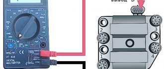
To do this, you can use the readings of the voltmeter in the instrument cluster. You need to turn on the ignition, and the needle will be in the middle of the scale, and a little later it will swing to the right (due to the power supply to the coil being turned off when the engine is not running). This arrow behavior indicates that there is no fault in the switch. In the event that there is no voltmeter, a test lamp is required to check the ignition. One end of it is connected to ground, the other to the output of the coil connected to terminal 1 of the switch. If you turn on the ignition, then if the switch is working properly, after a while the lamp will burn brighter.
However, in some cases, the ignition malfunction is not related to a switch failure. It is necessary to check the condition of the wires, first of all, contact with ground and the condition of the connectors. It is also necessary to check the Hall sensor.
The appearance of a voltage switch in the design of a car, including the domestic VAZ 2108, was a natural result of the development of the ignition system. Its further improvement was the use of first dual-channel and then multi-channel switches to improve operating efficiency. » alt=»»>
Checking the 2109 switch yourself on a VAZ, or simply “nine” car is something that sooner or later every owner of this domestic car may encounter.
This small electrical device, if it fails, makes operating the car difficult or even impossible.
In our material we will analyze in detail: what is this switch, why is it needed and how to determine whether it is working?
Content:
How to check and ring the ignition module of a VAZ-2114
In a car, each part is assigned certain functions. The ignition module also performs a number of important tasks, for example, when it breaks down, the engine is not able to work properly and it becomes difficult to start the car.
Functions of the VAZ-2114 ignition module
The ignition module in the VAZ-2114 solves important problems in the functioning of the car:
- first creates pulses passing through high voltage;
- then transfers them to the spark plugs.
The power supply of the unit involves operation starting from the on-board system of the vehicle, the minus wire is controlled by the body of the car. The subtlety of the module’s operation is that it simultaneously produces 2 sparks, one of which occurs at the moment of maximum compression of the air-fuel mass, and the other depends on the release, which is why it is called idle.
As for the connection method, the spark plugs are connected to the 1st and 4th cylinder, and the idle sparks fit to the 2nd and 3rd cylinder structure.
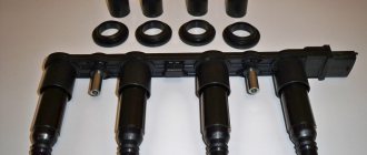
What does the ignition module consist of?
The ignition module built into the VAZ-2114 consists of 2 high-power transformers and the same 2 electronic-based control units. One side of the product has 4 outputs at once; they are responsible for connecting the candles. To keep the structural components in their original form and protect them, the manufacturer provides a plastic coating. The weight of the entire structure slightly exceeds 1 kg.
The spark plugs suitable for the engine are fixed together with the ignition module by running high-voltage wiring. A device called a “controller” controls the process. First, he takes the performance indicators of the structure, then analyzes them and, finally, decides what should be changed to achieve optimal performance - the crankshaft rotation speed, the temperature reached by the coolant in the VAZ-2114, or the engine load.
Frequent malfunctions of the VAZ-2114 ignition module
The following malfunctions occur in the VAZ-2114 ignition module:
- intermittency is formed at idle;
- power indicators leave much to be desired;
- the engine is not working correctly;
- in the paired operating mechanism, the cylinders are acting up (that is, the functioning of only one pair of cylinders can be heard);
- if the Check Engine light comes on.
If you suspect a faulty factory module in your car, then it's time to check the ignition module. It doesn’t hurt to make sure with your own hands that the wires are connected correctly and firmly; check that the spark plugs remain intact and are not damaged. Before you begin diagnostics and repair work, you need to stock up on protective equipment that will protect you from dangerous situations - the tool must be treated with insulating material, and gloves are required.
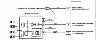
The switch is the basis for uninterrupted engine operation
The VAZ 2109 car is equipped with a contactless ignition system.
The system includes spark plugs, four high-voltage wires (one for each spark plug), a Hall sensor, a distributor, an ignition coil and, in fact, a switch.
Rice. 1 Ignition circuit of VAZ 2109 Schematic illustration.
The ignition system generates an electrical impulse (spark), thereby igniting the mixture of fuel and air in the combustion chambers necessary for engine operation.
The switch is responsible for the cyclic supply of pulses to the ignition coil, this is necessary for the proper operation of the entire system as a whole.
Thus, if the switch is faulty, the spark will supply intermittently or be completely absent. It is not possible to drive such a car.
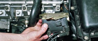
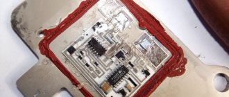
The VAZ 2109 switch itself consists of an aluminum case and a microcircuit installed on it. The device is mounted in the engine compartment and connected by wires to the ignition coil.
Rice. 2 Appearance of the VAZ 2109 switch.
The design of the housing and the mounting method allow the switch to successfully withstand vibrations that occur when the car is moving.
The VAZ 2109 contactless ignition system switch has the following performance characteristics:
- Voltage range 6–16 Volts.
- Operating voltage 13.5 Volts.
- Switching current 7.5–8.5 Amperes.
- A switch in good condition ensures an uninterrupted supply of spark to the cylinders with a crankshaft speed of up to 7000 rpm.
SZ scheme
The ignition system used on the VAZ 2109 includes the following components:
- Switch;
- Candles;
- Distributor sensor;
- Ignition coils;
- Switch;
- Locking device. It does not allow the starter to turn on until the ignition is completely turned off;
- Locking and anti-theft device;
- Hall Sensor;
- The sensor-distributor roller, which is located horizontally and receives torque from the camshaft;
- System of spontaneous ignition shutdown, which is activated after 2-8 seconds;
- Switched current equalization system, which is required when the network voltage changes within the range of 6-18V;
- The system built into the switch, which regulates the time of energy accumulation in the coil, limits the current strength at low motor operating frequencies.
The ignition system operates with a voltage of up to 26 kV, the spark charge has a duration of 1.6-2.0 milliseconds, and the energy released during this time is 35-50 MJ.
Service
If you do not monitor the state of the system and lose sight of the presence of malfunctions and malfunctions, this can lead to certain consequences. Namely:
- Reduced reliability of the operation of the protective equipment, the occurrence of failures;
- Reduced technical characteristics of the engine, such as acceleration dynamics, maximum speed;
- A sharp increase in the amount of fuel consumed;
- Failure of SZ elements or the entire system.
Before you carry out maintenance on the SZ yourself, take into account several important recommendations.
- Do not touch the ignition coil with your hands while the engine is running. This applies to wires, switch and other components.
- Do not test the SZ for performance using the “spark” method, as this can lead to injuries and costly repairs of the entire vehicle;
- Under no circumstances should you start the engine with a spark gap between the central terminal of the distributor sensor and the high voltage.
Signs of a broken switch
During the operation of the car, unpleasant symptoms may occur, indicating a malfunction of the ignition system.
A possible reason for this may be incorrect operation of the switch. Here are the most common symptoms that should suggest a possible breakdown of this device:
- Can't start the engine. There is no spark when the starter is running.
- The engine starts and runs normally at low and medium speeds, but cannot be revved up at high speeds. The engine is not running at full power.
- The car stalls when moving away, although it idles stable.
- The engine starts, but does not run for a long time and immediately stalls.
- The engine begins to operate unstably - “triple”, reaching a certain speed level. When cold it can start quite normally.
- The engine may periodically, without any pattern, stall, then work normally again. The battery discharge indicator lights up. The tachometer needle shows sharp changes in the number of revolutions.
Verifying switch operation
Every car enthusiast with a sufficient level of desire and minimal technical skills can check the operation of the switch.
The easiest way to check is to replace the unit with a new one that is known to be good. If after this the problems in the engine operation have disappeared, then we can conclude that the old switch has already served its purpose.
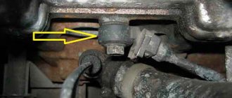
Every car enthusiast can replace the switch independently. First of all, you need to find it under the hood of the car.
The switch is located in the area of the left (driver's) pillar. It is connected by wires to the coil.
Rice. 3 Engine and organization of the engine compartment of the VAZ 2109.
1 – front glass of the shock-absorbing strut; 2 – water tank; 3 – air filter; 4 – fuel pump; 5 – steering rack; 6 – camshaft sensor; 7 – vacuum brake booster device; 8 – master cylinder of the brake system and its barrel; 9 – switch; 10 – fuses; 11 – engine cooling system tank; 12 – battery; 13 – hood fastening; 14 – ignition coil; 15 – starter; 16 – high-voltage wires; 17 – neck for oil; 18 – engine; 19 – candles; 20 – windshield washer system.
Next, disconnect the negative terminal from the battery. Then you should carefully disconnect the plastic bracket with wires from the switch. To do this, you need to release the spring clip.
Then we unscrew the nuts that secure the aluminum switch housing to the car body. Under the left nut there will be a ground terminal.
Remove the switch from the studs and replace it with a new one. The new one is installed in the reverse order.
Repair and replacement instructions
It is worth noting that modern Russian switches are suitable for output key transistors not only of standard production, and in particular KT890A, KT898A1, but also the foreign analogue BU931. It can be implemented either without a housing or in the TO-220 or TO-3 design.
As for the control circuit, the 78.3734 series switches are suitable for:
- 4-channel amplifier type K1401UD2B;
- domestic microcircuit R1055ХП1;
- foreign L497B SGS-TOMSON.
Before replacing the switch or its components, it is recommended to test the integrity of the wiring and connections of the ignition system. Pay special attention to the generator. It is also a good idea to check the voltage from the on-board network to the Hall sensor.
More details on faults and how to repair them are given in the table below.