The design of the gas distribution mechanism of an internal combustion engine: purpose, principle of operation
The main purpose of the gas distribution mechanism (GRM ) is the timely supply of a combustible mixture of fuel and air (fuel-air mixture) into the combustion chamber and the removal of gases from the engine cylinders.
The work of the timing belt is to timely open and close the intake and exhaust valves, for which the valve mechanism is responsible.
What is a gas distribution mechanism (GRM)?
The gas distribution mechanism (GRM) is a mechanism designed to inject fresh charge into the engine cylinders (fuel mixture in classic gasoline engines or air in diesel engines) and release exhaust gases in accordance with the operating cycle, as well as to ensure reliable isolation of the combustion chamber from the environment during time of compression strokes and power stroke.
Depending on the type of devices that inject charge and exhaust exhaust gases, there are two types of gas distribution mechanisms:
The valve train is the most widely used and is used in all four-stroke engines. Upper and lower valve locations are possible. The upper location is currently used more often, since in this case the gas exchange process is more efficient. Typical designs of gas distribution mechanisms with overhead valves are shown in the figure.
What does the gas distribution mechanism (GRM) of the engine consist of?
The main elements of the gas distribution mechanism are:
For V-shaped engines, the main part of the mechanism in question - the camshaft - can have either a lower or an upper location. With a lower location (Fig. a), the camshaft 7, located in the crankcase, is driven into rotation from the engine crankshaft using a gear drive, usually containing one pair of cylindrical or bevel gears (several pairs of gears can be used).
For a four-stroke engine, the drive ratio is two, i.e. The camshaft rotates twice as fast as the crankshaft. When rotating, the camshaft, with the help of cams, moves the pushers 2 and rods 3. The latter rotate the rocker arms 5 relative to the axis 4. At the same time, the opposite ends of the rocker arms act on the valves 7, moving them down and overcoming the resistance of the springs 6. The location of the cams on the camshaft and their shape is chosen so that the intake and exhaust valves open and close at strictly defined points according to the operating cycle of the engine.
Rice. Gas distribution mechanisms with an upper valve arrangement: a - with a lower camshaft arrangement: 1 - camshaft; 2 - pusher; 3 - rod; 4 — rocker axis; 5 — rocker arm; 6 - spring; 7 - valve; b - with an overhead camshaft: 1 - screw; 2 - lock nut; 3 - rocker arms; 4 - camshaft
For in-line overhead valve engines and V-engines with four valves per cylinder, the camshaft(s) are located in the cylinder head, in close proximity to the valves (Fig. b). Since with an overhead camshaft the distance between its axis and the axis of the crankshaft is significant, a chain drive is usually used to drive the camshaft into rotation. For engines of relatively low power, a toothed belt can also be used.
The camshafts of powerful V-shaped diesel engines are driven into rotation using a gear drive, in which the number of pairs of bevel gears can be two or more. With an overhead camshaft, the number of transmission parts is reduced. For example, in the mechanism shown in Fig. b, there are no pushers and rods. The camshaft 4 directly acts on the rocker arms 3, which, in turn, move the valves.
When the engine is running, the parts of the gas distribution mechanism heat up (the valves most strongly) and, therefore, expand and elongate. To ensure that the valve stem can be lengthened when it is heated without disturbing the tight fit of the valve head in the seat, there must be a gap between the individual parts of the gas distribution mechanism of a cold engine (for example, between the valve stem and the end of the rocker arm). This gap can be adjusted in various ways, for example, using screw 1 (see Fig. b), the self-unscrewing of which is prevented by locknut 2. To eliminate the need to adjust the gap and reduce engine noise, hydraulic pushers are used in the gas distribution mechanisms of many modern engines. These pushers have built-in hydraulic compensators that change their length under the influence of oil pressure, which is specially supplied from the engine lubrication system. The valve, its guide sleeve, spring and support washer with its fastening parts form the valve group of the gas distribution mechanism.
The valve consists of a head and a rod, between which a smooth transition is made to reduce resistance to the movement of gases. The valve head has a ground conical working surface - a chamfer along which the valve fits tightly to the seat. To secure the spring support washer, the end of the valve stem is provided with a groove. In some cases, to improve heat removal from the exhaust valve head, the rod on the side of the head is made hollow and liquid metallic sodium is introduced into it.
Valves are made by upsetting from a steel bar, followed by mechanical and heat treatment. The material for them is wear- and heat-resistant steel. Sometimes the head and stem of the exhaust valve are made of different grades of steel and then connected by welding. The end of the valve stem is additionally hardened to increase hardness and wear resistance. In some cases, a particularly heat-resistant alloy is welded onto the chamfer of the exhaust valve to increase its durability.
Each engine cylinder has at least two valves - intake and exhaust. However, there is currently a trend towards an increase in the number of valves per cylinder. Engines with three (two intake and one exhaust) and four (two intake and two exhaust) valves are increasingly being used. With one intake and one exhaust valve, the first one has a larger head. This is necessary to better fill the cylinder with fresh charge.
The guide sleeve through which the valve stem passes ensures its precise fit into the seat. The rod has a high-precision interface with the bushing (the gap is 0.05... 0.12 mm). Guide bushings are made of cast iron or sintered porous material, which can be impregnated with lubricating oil.
The valve spring holds the valve in the closed position, ensuring it is firmly seated. The springs are made by cold coiling from special steel, heat-treated wire, followed by shot blasting, which increases their durability. Sometimes, to prevent the occurrence of resonant oscillations, springs with variable coil pitches are used.
The support washer keeps the spring compressed. The valve stem is secured to the support washer using conical split nuts that fit into a recess on the stem.
The valve seat, into which it sits with the chamfer of the head, is located in the cylinder head for an overhead valve engine. Typically, exhaust valve seats, and sometimes intake valve seats, are made in the form of insert rings and are tightly pressed into the recesses of the cylinder heads. Insert rings are made of heat-resistant steel, special cast iron or sintered material.
The transmission parts of the gas distribution mechanism ensure the transmission of force from the camshaft to the valve stems. Such details include:
Pushrods transmit axial force from the camshaft lobes to the valve rods or valve stems. They can be flat, mushroom-shaped, cylindrical or lever-shaped. They are made of steel or cast iron. To increase hardness and wear resistance, the working surfaces of the pushers are hardened and then ground.
The rods serve to transmit forces from the pushers to the rocker arms with a lower camshaft in an overhead valve engine (see Fig. a). The rods are made of steel or aluminum alloy, giving them the shape of a tube. At the ends of the rods, steel tips with spherical surfaces having high hardness are attached. The lower ends of the rod rest against the sockets of the pushers, and the upper ends rest against the adjusting screws of the rocker arms.
Rocker arms are designed to change the direction and magnitude of forces transmitted to the valve stems. The rocker arms are hingedly mounted on axles that are attached to the cylinder head. An adjusting screw can be installed at one end of the rocker arm, which allows you to change the clearance in the gas distribution mechanism. The material for the rocker arm is steel or ductile iron. The working surfaces of the rocker arm are hardened and then ground.
The camshaft serves to timely open and close the valves using cams. The design of the camshaft depends on the type of engine, the number of cylinders and valves, and the type of drive. Typical camshaft designs are shown in the figure. Any camshaft has cams for intake 2 and exhaust 4 valves, as well as support journals 2. The camshaft of a gasoline carburetor engine is also equipped with a helical gear 5 that drives the oil pump and ignition distributor and an eccentric 3 that drives the fuel pump. The number of cams corresponds to the total number of valves that are served by a given shaft. The number of bearing journals is most often equal to the number of main journals of the crankshaft. In an in-line four-cylinder engine, the tops of the cams of the same name are located at an angle of 90° (Fig. a), in an in-line six-cylinder engine - at an angle of 60° (Fig. b), and in a V-shaped eight-cylinder engine - at an angle of 45° (Fig. c) . The installation angle of the opposite cams depends on the valve timing. The tops of the cams are positioned in accordance with the operating order accepted for the engine, taking into account the direction of rotation of the shaft. As bearings for the camshaft, thin-walled bimetallic or trimetallic bushings are most often used, pressed into the crankcase (for a lower location) or the cylinder head (for an upper location). One of the shaft support journals (usually the front one) is equipped with a locking device to prevent its axial movements. To lubricate the bearing journals, oil is supplied to them under pressure from the general engine lubrication system. When the camshaft is located at the top, an axial hole is drilled in its body, through which oil flows to all support journals and cams.
Rice. Camshafts of in-line four-cylinder (a), in-line six-cylinder (b) and V-shaped eight-cylinder (c) engines with cam layouts: 1 - support journal; 2, 4 — cams of intake and exhaust valves; 3 — fuel pump drive eccentric; 5 - helical gear of the oil pump drive
Source
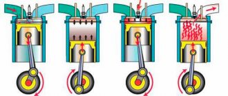
Principle of operation
The operation of the gas distribution mechanism is difficult to consider separately, in isolation from the engine operating cycle. After all, its main task is to open and close the valves in time for a certain period of time. Accordingly, on the intake stroke, the intake valves open, and on the exhaust stroke, the exhaust valves open. That is, in fact, the mechanism must implement the calculated valve timing.
Technically it happens like this:
It is also worth noting that during a full operating cycle, the camshaft makes 2 revolutions, alternately opening the valves in each cylinder, depending on the order of their operation. That is, for example, with a 1-3-4-2 operating scheme, at the same moment in time, the intake valves will be open in the first cylinder, and the exhaust valves in the fourth. In the second and third the valves will be closed.
Thermal expansion problem
The timing device ensures normal engine operation, but certain problems arise. This refers to the thermal expansion of the metal from which the valves are made as it is exposed to high temperatures during fuel combustion. When heated, it elongates and cannot tightly close the hole in the cylinder, which significantly reduces compression. To ensure that the valve does not extend into the cylinder, but upwards, a thermal gap of 0.2 mm is made between the plate and the cam or the rocker and the cam. This gap is set and checked with a special feeler gauge, and adjusted with a screw or bolt.
In modern engines, to combat thermal expansion, other parts of the gas distribution mechanism are used - hydraulic compensators. In this case, valve adjustment is not required; the gap is set and adjusted automatically. If hydraulic compensators begin to tap, this indicates problems in their operation, since they do not have time to select gaps. The main reasons for this problem are a breakdown of the hydraulic compensator itself, which must be replaced, or, less commonly, a blockage or poor operation of the lubrication system.
Classification or types of timing belts
Engines may have different gas distribution mechanism layouts. Consider the following classification.
According to the location of the camshaft
There are two types of camshaft position:
With a lower position, the camshaft is located in the cylinder block next to the crankshaft. The force from the cams is transmitted through pushers to the rocker arms, using special rods. They are long rods and connect the pushrods at the bottom to the rocker arms at the top. The lower location is not considered the most successful, but it also has its advantages. In particular, a more reliable connection between the camshaft and the crankshaft. This type of arrangement is not used on modern engines.
In the upper position, the camshaft is located in the cylinder head (cylinder head) directly above the valves. In this position, various options for influencing the valves can be implemented: through pushers, rocker arms or levers. This design is simpler, more reliable and compact. The overhead camshaft position has become more widespread.
By number of camshafts
In-line engines may have one or two camshafts. Engines with one camshaft are abbreviated SOHC (Single Overhead Camshaft), and those with two camshafts are abbreviated DOHC (Double Overhead Camshaft). One shaft is responsible for opening the intake valves, and the other for opening the exhaust valves. V-engines use four camshafts, two for each cylinder bank.
By number of valves
The shape of the camshaft and the number of cams on it will depend on the number of valves per cylinder. There may be two, three, four or five valves.
The simplest option is with two valves: one works for inlet, the other for outlet. In a three-valve engine, two operate for intake and one for exhaust. With four valves: two for intake and two for exhaust. Five valves: three for intake and two for exhaust. The more valves at the intake, the greater the volume of the air-fuel mixture entering the combustion chamber. Increases engine power and dynamics. The size of the combustion chamber and the shape of the camshaft will not allow making more than five. The most common design is with four valves per cylinder.
By drive type
There are three types of camshaft drive:
The chain resource is enough for an average of 150-200 thousand kilometers.
The main problem with a chain drive is considered to be the breakdown of tensioners, dampers or rupture of the chain itself. If the tension is poor, the chain can jump between the teeth during operation, which leads to a violation of the valve timing.
Hydraulic tensioners help automatically regulate chain tension . They are pistons that press on the so-called shoe. The shoe is directly adjacent to the chain. It is a curved part with a special coating. Inside the hydraulic tensioner there is a plunger, a spring and a working cavity for oil. Oil enters the tensioner and pushes the cylinder to the desired level. The valve closes the oil channel, and the piston constantly maintains the desired chain tension. Hydraulic compensators in the timing belt operate on a similar principle. The chain damper dampens residual vibrations that the shoe did not dampen. This ensures optimal and precise operation of the chain drive.
The biggest trouble can come from breaking the chain.
The belt resource is also limited and on average it is 60-80 thousand kilometers.
Toothed belts are used for better grip and reliability. This drive is simpler. A belt breaking while the engine is running will have the same consequences as a chain breaking. The main advantages of a belt drive are ease of operation and replacement, low cost and silent operation.
The operation of the engine, its dynamics and power depend on the correct operation of the entire gas distribution mechanism. The greater the number and volume of cylinders, the more complex the timing device will be. It is important for every driver to understand the structure of the mechanism in order to notice a malfunction in time.
Source
The gas distribution mechanism (abbreviation - timing) is a set of elements that guarantee the correct operation of the intake / exhaust valves of the power unit.
The operation of the unit is synchronized with the crank device to avoid contact of the piston and valve mechanisms after starting the engine. Below we will consider in detail why a timing belt is needed, how it works, what types there are, and what their features are.
Purpose of the gas distribution mechanism
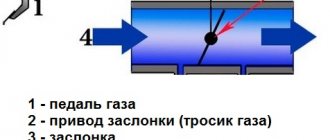
In simple words, the timing belt is necessary to supply the finished fuel mixture to the engine, as well as to release burnt fuel into the cavities of the cylinders. This function is enabled by valves that open/close at specific times. Most internal combustion engines use a 4-stroke principle, which ensures the conversion of thermal energy into mechanical energy.
The entire process takes place in a cylinder group, where valves and pistons move synchronously in a certain sequence in compliance with the phases. In this case, the timing functions include moving the valves in interaction with the crankshaft. Depending on the situation, the intake/exhaust valves open/close.
Conventionally, the purpose of the timing belt is to ensure the operation of the following four phases:
The engine gas distribution mechanism guarantees accurate and timely opening of the intake/exhaust valve units. In this case, the timing interacts with the crankshaft, and rotation is transmitted to the camshaft using a chain, belt or gears. We will dwell on this issue further below.
Valve timing
The valve timing phases are considered to be the beginning of the opening and the moment of closing of the valve, expressed in degrees of the crankshaft rotation angle relative to the dead points. The best cleaning of the cylinder from exhaust gases is achieved by opening the exhaust valve before bottom dead center (BDC), and closing after TDC. The cylinders are filled with air or a combustible mixture when the intake valve opens before it passes TDC, and closes after BDC. The period of simultaneous opening of both valves is called their overlap.
The phases are selected experimentally at the engine manufacturer, and depend on its design and speed. In this case, the oscillation of gases is used in such a way that before the closing of the intake valve there is a pressure wave in front of it, and before the closing of the exhaust valve there is a rarefaction wave. This selection of phases simultaneously improves the filling of the cylinders with air or mixture, as well as their cleaning from exhaust gases.
The timing mechanism is installed using marks on the gears. A deviation of a couple of teeth or sprockets can cause the valve to hit the piston and cause engine damage. The constancy of the phases is maintained in the presence of a thermal gap in the valve mechanism, violations of which cause a decrease or increase in the opening duration.
For each engine, the manufacturer indicates the valve timing in the form of a diagram showing the opening, closing, and overlap moments of the valves.
Principle of operation
To understand the principles of operation of the timing belt, it is important to know its structure, design features and the purpose of various elements. The system consists of valves and a camshaft with drives. Each element performs a specific function.
Valves
A key timing element that ensures the supply of fuel to the cylinder and the removal of exhaust gases. Structurally, it is a rod, flattened towards the end.
On new engines they are located on the cylinder head, and the contact point is the “saddle”. The element in question may be intended for inlet and outlet. The intake valve diameter is slightly larger.
In manufacturing, a metal alloy is used that provides resistance to high temperature and pressure. The intake valve stem is solid, while the exhaust valve stem is empty inside. In the latter case, a sodium composition is used inside for better heat removal.
Modern engines are usually equipped with pairs of intake/exhaust valves. In other words, there are 4 valves installed on each cylinder, and a total of 16 valves. But there are other options - with 2, 3 and 5 valves (more on that below). The movement of the valves is provided by a drive built on hydraulic pushers or a roller-type lever.
Spring
An element that secures the valve in a closed position. The spring is installed on a rod using crackers and a plate. The rigidity of the product is sufficient for tight closure and vibrations during operation.
Roller lever
Such a unit is used in most cases, and it is this unit that plays the role of the drive mechanism for the valve system. Structurally, one part of the lever “stands” on the valve stem, and the second - on hydraulic compensators or a ball. To reduce losses, the contact point between the cam and the camshaft lever is made in a roller form.
Hydraulic compensator
The use of this element ensures zero clearance in any position, which reduces noise and makes the motor run smoother. The hydraulic compensator is a special cylinder with a spring-loaded piston. The device is placed directly on the valve tappet.
Camshaft
The functions of the engine camshaft include ensuring the operation of the timing belt, taking into account the required order of operation of the cylinders and phases. Structurally, the device consists of a shaft with cams. They act on the valves and contribute to their opening and closing. In this case, the shape of the cams ensures the required time in the open or closed position.
Additional nodes
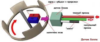
In modern engines, auxiliary devices are often installed to ensure the correct functioning of the gas distribution mechanism. This group includes a camshaft position sensor (Hall), which determines the position angle and sends signals to the engine ECU. Some cars are equipped with systems that regulate valve clearances (hydraulic compensators, mentioned above). Taking into account the above, we can consider the timing algorithm in general form:
In practice, there are examples of engines without a timing drive and camshaft. The downside is that such designs have a low degree of reliability.
What is the purpose of the belt?
The timing belt is a part whose purpose is to act as a connecting link.
Thanks to the timing belt, the camshaft and crankshaft work synchronously, which contributes to the proper functioning of the engine as a whole. This is the need for using a strap.
Markings on the strap
Let's look at a few examples of translating the timing belt decoding:
- ISO-58111x19. The first two numbers (58) encrypt a series of teeth used on the product. In this case, the pitch and profile will be without a groove, the shape will be semicircular, and the height will be 3.5 mm. Then there are three numbers (111), which indicate the number of teeth. By number 19 you can determine the width of the product. There are belts on sale whose teeth are made in the form of a rounded trapezoid.
- 58127x3/4 HSN. Here the first two digits also indicate a series of teeth. The numbers 127 indicate their number, but you need to take into account that in straps belonging to the 40 series, this number is conditional. The numbers 3/4 indicate the width of the product in inches. In this case it is also 19 mm. The HSN mark at the very end indicates that the product is made of durable, highly saturated nitrile. This material has proven its strength. If there are no such letters at the end, then the strap is made of neoprene rubber.
Table: Belt markings
Manufacturers may label their products differently. The table shows how to decipher the timing values.
Timing belt classification
When considering the features of the gas distribution system, it is necessary to take into account that it may vary in the position and number of camshafts, the number of valves and the type of drive mechanism (chain, belt, gear, combined). Let's take a closer look at the different options.
By camshaft location
Structurally, the camshaft can be located in one of two places in the engine:
By number of camshafts: DOHS and SOHS
Modern engines can have one or two camshafts. In the first case, the system is called SOHC (single overhead camshaft) or DOHS (double overhead camshaft). As you can see, in both cases the mechanism is located at the top.
When using the double version, each of the shafts has an individual function. The first is responsible for opening, and the second is responsible for closing the valve mechanism. V-shaped engines can use as many as four camshafts. They work in pairs on both groups of cylinders.
By number of valves
The key factor is the number of valves used, because the type of camshaft and the number of cams depend on this. The number of valves per cylinder can be from two to five. Let's briefly look at the main options for the number of valves:
The higher the number of valves on the intake system, the greater the volume of fuel entering the engine.
As a result, the power and dynamics of the motor increases. Let us immediately note that it is impossible to install more than five valves due to the characteristics of the camshaft and other engine mechanisms. Most often, the system is limited to four elements.
By drive type
When analyzing the gas distribution mechanism, it is also necessary to take into account the types of drive. There are four possible options here.
Chain
The most reliable option is a timing chain. In this case, sprockets (gears with teeth) are mounted on the camshaft and crankshaft. They are combined using a special chain, and the system is closed from above with a special housing. As the crankshaft rotates, the sprocket pulls the chain, which in turn rotates the camshaft gear.
Structurally, the chains differ in type or number of rows. In the first case, they are divided into gear, roller and bushings, and in the second they range from two to four rows. If there are several camshafts, a corresponding number of chains can be used.
The average resource of such a mechanism is 170-200 thousand kilometers. Most often, gears or additional components (tensioners, dampers) are damaged. As a result, the chain jumps to other areas, which leads to disruption of the timing belt and damage to the valves. In the event of a breakdown, it may be necessary to replace the chain and auxiliary mechanisms.
Belt
The second most popular is the timing belt. Unlike the option discussed above, here pulleys or gears are installed on the shafts. A belt connector is pulled on top of these units to ensure rotation transmission. The belt can be V-belt (toothed) and poly-V-ribbed. In the first case, gears with teeth are mounted on the shafts.
Additionally, the belt drive has several types of rollers (tensioning, support). The former provide the necessary belt tension, and the latter play the role of support and protect against slipping.
Gear
This drive option is used in rare cases. Structurally, it implies the presence of gears on the crankshaft and camshaft, which are combined with each other not using a belt / chain, but using other gears. In essence, the principle of operation of a watch is repeated, when the torque is transmitted by meshing the teeth of different sprockets.
The rarity of the use of such a drive is explained by the fact that the camshaft and crankshafts are located at the top and bottom, respectively, at a large distance. That's why you have to use a belt or chain. If both mechanisms are located below, the use of the gear principle is quite possible. At the same time, it is reliable, but has great complexity. Found in Nissans on AXD, AX or BLJ engines. The weakest point is the teeth of the sprockets, which can break.
Mixed
Some manufacturers use a mixed version when gear and chain drives are used.
There are many such schemes, but they are used in rare cases. Sometimes a chain and belt are even used at the same time. There are dozens of options, so when buying a car you need to ask which one is provided in your case. Most often, complex motors are found in Japanese or Korean internal combustion engines.
Pros and cons of belt drive
The belt drive gained its popularity due to its advantages compared to similar types of drives.
- Despite the fact that the production of such structures is more complicated than chain ones, they are much cheaper.
- It does not require constant lubrication, due to which the drive was placed on the outside of the power unit. As a result, replacing and diagnosing the timing belt has become much easier.
- Since in a belt drive the metal parts do not interact with each other, as in a chain drive, the noise level during its operation has decreased significantly.
Despite the large number of advantages, the belt drive also has its disadvantages. The service life of a belt is several times lower than that of a chain, which causes its frequent replacement. If the belt breaks, it is likely that the entire engine will have to be repaired.