The introduction of standards for the car radio connector, called the ISO connector, allowed car owners to change car radios from different manufacturers without having to cut and connect the wire in accordance with the diagram of each specific manufacturer. But when replacing an old radio, the pinout of the ISO connector of the car radio may still be useful, and now we will analyze it in detail.
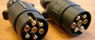
Externally, the ISO standard connector looks like a rectangular connector with eight pins. And there are two such connectors, one connector is needed to power the radio, output the REM wire, power the antenna, etc., and the second is for connecting speakers.
Using the following illustration, we will provide a detailed description of the purpose of each contact:
Markings and types of connectors
Today, all car radio connectors comply with the ISO standard, and two connectors are used. Each is a plug with eight pins, sometimes the manufacturer can combine them into a single housing. Energy consumption sources are connected to one of them; it is marked with the letter A. As for the second, acoustics, that is, speakers, are connected to it. The connector designation is marked with the letter B.
Adapters for car radio connectors
Head units with three outputs can be found on sale, but they are rare and usually represent an exception.
Even if the connected sockets do not correspond to each other, the car owner has several connection options:
- You buy a special adapter for the radio, which can be connected to the outputs of the speaker system.
- The second method is considered “collective farm” among car enthusiasts. Its essence is to cut off the non-standard output and wind the necessary wires to it. But we do not recommend using this option, because eventually the wires will begin to unwind, so the “collective farm” procedure will have to be repeated. In addition, the cost of adapters is not so high to use this method.
How to connect
To connect the Pioneer car radio, you can use 2 methods.
- Through a standard ISO connector.
- Without using standard connectors.
The first option using ISO connectors is preferable, but it may not be used in all cases. So in some car models there are simply no suitable connectors for connection. If this option is chosen, then there should be no difficulties. In this case, based on the color connection diagram, you need to correctly connect the connectors to the mating parts.
If there are no connectors for connection, you can go in other ways. For single-unit and dual-unit devices, the process for connecting the Pioneer radio will be slightly different.
Connecting 1 din occurs in several steps:
- The decorative panel is removed from its seat using a screwdriver.
- The plugs are removed from the wires, after which the wires need to be connected to the mating ones (a diagram will help with this).
- To protect against short circuits, each connection must be carefully insulated.
- The wires are secured with clamps, which increases the reliability of the overall structure.
You need to connect the Pioneer 2 din radio in a slightly different way:
- If there is no battery wiring in the car, you should use a stranded wire. It is not recommended to use the wires provided in the kit, since their cross-section is not large enough. In this case, the length of such a connection cable must be no less than the distance from the battery to the place where the radio is connected.
- When connecting, do not twist the wires together, as this may cause a decrease in power and interference.
- To properly connect the Pioneer car radio, the wires from the batteries must be connected after completing the assembly of the device.
Scheme
Before connecting the Pioneer car radio using ISO connectors, you should study the entire wiring on the new device. The connectors are a group of contacts (each contains 8 wires).
During installation of the radio, the connection occurs as follows: each contact is connected to the speaker system on one side, and to the power supply on the other side. This system is called pinout of car radio connectors.
Toyota
Adapter from the manufacturer Intro. Responsible for connecting the power supply and acoustic (sound) signal from the ISO connector to the standard radio socket for Japanese-made cars:
- Toyota;
- Lexus;
- Daihatsu.
Renault
ISO adapter from the manufacturer Intro for quickly connecting a modern multimedia system (MMS) or other non-standard device (radio tape recorder) to the place of the factory device. An adapter device of high quality at an affordable price, recommended for installation on cars of the following brands:
- Peugeot;
- Citroen;
- Renaults produced after 2005.
This technical adapter device is a plug for connecting to the standard connector of the player and the connector for the electrical wiring of the car. Without any special tools in a short period of time.
All you need to do is buy an ISO adapter
at an affordable price, and you can independently connect the car radio in the shortest possible time. At the same time, safety from incorrect connections, short circuits and other difficulties is guaranteed.
When you can't do without an ISO adapter
When purchasing a car with medium or higher equipment, the owner receives a standard car radio. Often its functions are limited to playing CDs, MP3 files, and listening to radio stations. The presence of a USB interface is much less common; only premium cars are equipped with a navigation system that allows you to display images from the rear view camera. Unfortunately, not everyone has the opportunity to buy a premium car; in other cases, the car radio is either completely simple or simply absent. The problem is solved by purchasing and installing one of the speaker systems offered on the modern market.
But here an additional difficulty arises - a warranty is provided for a new car, but it is preserved only if the owner adheres to all the rules for operating the vehicle. One of them is not to tamper with the car's electrical wiring. Therefore, many dealers prohibit installing radios and other equipment in third-party service centers. The problem is exacerbated by the fact that many car manufacturers use their own mounts, connectors and form factors, resulting in additional difficulties in installing the speaker system.
Methods for connecting a new radio
If the driver decides to replace the standard car radio, then he has two options:
- Cut off the “original” connectors and twist and solder the wires, and then insulate them. If, after solving the problem in this way, you contact the dealer to take advantage of the car’s warranty service, the probability of receiving a refusal will approach 100%. In addition, in the future it will be difficult to return everything to its original place. It is difficult to expect high quality from the resulting connection - when there is frost outside, the wires become tanned, and the twisting encounters vibration while driving, as a result of which the contact may disappear or periodically disappear.
- Select and purchase the appropriate ISO adapter
. This is the optimal solution to the problem - there is no need to make any changes to the car wiring, or damage the standard connectors. All that is required is to remove the plugs or the “original” car radio, and then install two adapters - for the antenna and for the electrics. This will take no more than 10 minutes! And if the driver has to go to a dealer’s service station, he can always return the standard radio.
The AvtoProfi store offers adapters for various car models. A wide range of adapters will allow everyone to choose the most suitable product that will facilitate the installation of a stereo system. And if you need additional help with choosing a product or making a payment, our employees will be happy to provide it.
A little theory: the pinout of the ISO connector of the radio is determined by the functionality of the contacts in the plugs, in accordance with their numbering. ISO radio connector is a connector for connecting a car's standard radio, certified according to international standards.
When trying to independently replace, for example, a car player from Pioneer with a JVC, car owners are faced with a situation where the wires in the plug are mixed up or do not even fit the shape of the connectors. In order to solve this issue, you need to buy an ISO plug, which is sold at any auto parts store. After that, pinout the head unit connector according to the diagram.
Kenwood radio ISO connector pinout
From this manufacturer (Kenwood) we were able to find several differences in the colors of the electrical wires and their purpose for the upper part of the connector block. The lower one, acoustic, fully complies with accepted standards. In order not to repeat ourselves, by default, the contact and option numbers we missed are also standard, as for all car head units. So, in our opinion, the following changes were minor:
- The yellow electrical wire goes to the car battery.
- The red cable goes to the ignition switch (ACC mode).
- Black braided wire - standard (grounding, ground).
- Blue and white wire - regulate power.
- A wire with a color combination of orange and white – adjusts the brightness of the car radio screen backlight (DIMMER).
Pinout problems
As a rule, no unexpected situations arise when connecting a car player via Euro connectors of the ISO 10487 standard. But only under the following conditions!
Your car is equipped with an ISO connection, both on the radio (a standard output for all global brands of this type of equipment) and on the side of the standard car electrics. This means that the previous owner (the car is not new) was not an experimental electrician, that is, he did not change the wires in the connection box or individual fragments of wires at his own discretion.
If the player was manufactured by someone unknown and where, like the connector itself, in such a situation you will need to arm yourself with a digital tester, brush up on your knowledge of electrical engineering and ring all the contact groups yourself. Based on the measurements, you can determine the power values of the wiring.
If the car radio is without a plug
Pinout of car radio connectors
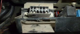
If the vehicle does not have ISO connectors for car radios, the car owner can install them himself. To do this, pinout is performed in the following order.
- If the plug is missing only in the car, you need to purchase an ISO connector from a specialized store. It must match the plug on the head unit that will subsequently be installed. If the plug is missing from the radio (in its place there is a bundle of wires), then you need to select a block.
- The first to be separated are the wires responsible for supplying voltage. Most often, they are distinguished by an increased cross-section and insulation in red and black colors. You can verify the correct choice using a test device.
- Separate the wires for the speakers according to the car's electrical diagram. During the connection, it is prohibited to connect the negative wires to the common line or ground.
- Separate the wire necessary for the antenna to operate.
- After the linear outputs on the radio are designated, they are connected to the rods of the new connector. To do this, the bare ends of the wire are secured with a crimping tool. This technique ensures reliable fastening.
- After connection, you should check the functionality of the device.
ISO connectors as the basis for connecting most radios
So, we realized that the radio may differ not only in appearance, but also in the connectors used to connect it. If these are unique standard radios, then they will probably need their own plug and pinout. If this is a radio tape recorder purchased for an unspecified car model, then it almost certainly has a connection via ISO plugs.
So what are these “almighty” ISO connectors? They look like this if you look at the back panel of the radio.
These connectors come with matching connectors of their own. In this case, in some cases adapters may be used. That is, when the cassette recorder has its own uniquely shaped contact-connectors, but ISO plugs are still installed at the other end
That is why we focused on the fact that the ISO standard for radio tape recorders exists as one of the dogmas! Often you can even find adapters for a specific radio model, be it Pioneer, Kenwood, Alpine, Sony, or even the Chinese Mistery, but they will come with an ISO adapter. Actually, this is a generally accepted and fully formed solution at the moment. After all, you can always switch from ISO standard connectors to the connectors you need, that’s the whole point!
Wire marking
Before you connect the Pioneer radio, find out what functions each of the wiring performs. Included with the device is a pair of ISO connectors for connection, each of them consists of 8 pins. The 1st is for the power supply, the 2nd is for the sound reproduction system. It happens that the car does not have the required port. In this case, disconnect the ISO, then connect using mechanical twisting. Multi-colored electrical wires are easy to identify. Each of them performs its own functions.
Purpose and connection of wiring
- Yellow. For batteries, supplied through a fuse.
- Red. Connects to the ignition. Red and yellow cannot be connected to each other, as the battery will quickly discharge.
- Black. Negative, it is fixed to the car body.
- White and blue. They come from the antenna, subwoofer and amplifier.
- Gray. For the right column (positive terminal). The gray wire with a black stripe is connected to the same speaker (minus terminal).
- White. It is connected to the positive terminal of the front left speaker, and the white one with a black stripe is connected to the negative terminal.
- Green. It is connected to the positive terminal of the left rear speaker, green with a black stripe - to the negative terminal.
- Violet. For the rear right column (plus), with a strip - minus.
You may also like…
Cars
How to connect via relay. Scheme
Cars
The radio works, but there is no sound: what could be the reason
Cars
How to change gears correctly on a manual transmission: learning to drive perfectly
Add a comment Cancel reply
Pinout of connectors by wires
Standard pinout of connectors when connecting via wires. To connect the radio in case of loss or breakage of the plug, simply remember or label each wire separately. You can find the correct pinout of the radio installed in your car on the Internet and download it as a picture.
Car radio pinout
Standard connectors used in cars such as Ford, Nissan, Toyota and many other foreign car brands use a 16-pin ISO connector of the European standard, which you can see in the photo below. Such connectors are often made double two by eight, which greatly simplifies the disconnection and connection of the head unit.
Manufacturers in European countries have adopted this connector as the basic one and have adopted the name FAKRA since 2000. A large number of signals are transmitted through such a connector, such as information about ignition, lighting, and speed. With the introduction of more and more functions into the car radio, the Iso connector for the radio changes over time and the pinout increases. For example, Ford, Nissan, Mercedes-Benz, Peugeot, Volkswagen and other European cars began to use a 40-pin connector called Quadlock.
QuadlockThis connector consists of 16 flat legs with additional connectors for other equipment. Auxiliary connectors are made in such a way that it is impossible to mix them up when connecting. It also includes a 12-pin plug for outputting audio signals and a 12-pin plug for inputting signals from various sources.
Purpose of contacts of the Euro connector in the Pioneer radio
After some time, after purchasing a new car, drivers have a desire to change the radio installed by the factory with a more functional “Pioneer”. And when replacing, you may encounter inappropriate pinouts of the radio's Euro connector by color. Or even with the connector design itself.
Car radio connector plug
In this case, it is possible to connect the radio to the Euro connector via an adapter and pin it out according to the diagram. Since the latest car radios are already available with a standard rectangular ISO connector, there shouldn’t be any difficulties.
Pinout of a standard Euro connector
The Euro connector is a standard plug for many modern devices. An ISO plug is installed on the machine, thanks to which it becomes possible to connect any model of radio with the appropriate connector.
Standards 1DIN and 2DIN
The difference between the standards lies in the size of the devices: a 2-din device is 2 times higher than a 1-din device.
The most common are 1-DIN radios, because Installation of higher devices due to the lack of a seat of appropriate size on the front panel of the car is not possible in every car.
There are 2 types of radio tape recorders:
- With proprietary connector. You need to choose a product whose pinout matches the desired car.
- With universal connector. The device connects directly to the ISO socket provided in the car.
Pinout is carried out according to ISO 10487 standard.
Upper power connector A
The connector serves as a connector between sources and consumers of electricity from the on-board network.
Plugs 1, 2, 3, 6 are rarely used in radio circuits of the lower and middle price segments. The elements are used when connecting additional options in higher quality player models. Wire colors may vary.
You should understand the purpose of the contacts:
- ANT. Used with a retractable antenna.
- Remote. Designed for connecting external amplifiers. Thanks to it, you can increase the number of mounted speakers, which is necessary in the interiors of large cars.
- Illumination. Adjusts the brightness of the player screen (the higher the driving speed, the less intense the backlight, so as not to distract the driver).
- Mute. Adjusts the sound of the device.
- A4. Turns the audio system on and off.
This connection scheme allows you to protect the battery from discharge, because turning on the system is possible only when you turn the ignition key, while the acoustic cascades consume electricity even when turned off.
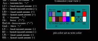
The pinout of the ISO connector of the radio (European) looks like this:
- Connector A5 (blue) is for the antenna. If the permissible current value (300 µA) is exceeded, both the amplifier stages and the entire head unit may break.
- Wire A7 (red) is intended to power the head unit. When it is disabled, the settings are returned to factory settings. Voltage - 12 V.
- Cable A8 (black). Responsible for connecting the speaker system to the car.
To protect the audio system, the wires must be equipped with a fusible link. If interruptions occur in the operation of the player, you should place a capacitor between connectors A7 and A8, which will act as a filter, smoothing out fluctuations in the electrical circuit.
Bottom speaker connector B
The speakers are connected through it as follows:
- Rear right + (purple).
- Rear right - (black and purple).
- Front right + (gray).
- Front left - (black and gray).
- Front left + (white).
- Front left - (black and white).
- Rear left + (green).
- Rear left - (black and green).
Most devices are designed for 4 channels; 8 wires are used for this (2 pieces per speaker).
The sound quality of the system depends on the “flattening”. If you mix up the connectors, the device will not fail, but the radio will not work correctly.
Audio system elements should be connected with cables with a cross-section of 1.5 mm or more. Thicker wires are used on power lines.
Standards 1Din and 2Din
The Din standard receives its designation from the abbreviation of the name of the German institute Deutsches Institut für Normung eV, which developed the standard in 1984. The purpose of introducing a single housing size for the audio head unit was to ensure interchangeability of equipment. Cars use radios of 1Din (178*50 mm) and 2Din (178*100 mm) sizes. There is also an intermediate version 1.5Din (178*75 mm), which is used to a limited extent by some manufacturers. All radios comply with a mounting depth of 160 mm.
Using the 2Din size allows for improved cooling of the radio amplifier and placement of additional devices (for example, a hard drive) inside the case. The increase in the front part allows the installation of a touch screen with a diagonal of 5″ and higher. Standard equipment has an original housing configuration; adapter frames are used to install head units from third-party manufacturers.
Japanese-made cars use original acoustic equipment with increased socket sizes.
For the Honda concern, the standard head unit size is 190*100 mm. Toyota uses radios of size 200*100 mm. Adapter frames and baskets are available to accommodate equipment that meets Din requirements in Asian vehicles.
The car radio power connection diagrams do not depend on the configuration and size of the case. To cross-connect 1Din and 2Din head units, ISO connectors with combined or separate plugs are used.
Possible problems and their solutions
The first problems may arise during the installation of equipment. If the radio does not fit completely into the landing shaft, then you should check the possibility of placing the housing in the instrument panel. Some cars require trimming of the internal structural elements into which the plugs or the rear wall of the device rest. The defect occurs due to jamming of the side latches (deformation or dirt ingress).
When using the device, there may be loss of sound from the speakers due to poor contact in the connecting cables. To restore functionality, you need to disconnect the plugs, inspect the connection points and reconnect the Pioneer radio. The defect occurs when the channels of an external amplifier break down; it is recommended to connect the speaker directly to the player. The damaged amplifier is repaired in a specialized service.
Doesn't turn on
If the head unit does not turn on when you press the keys, then you need to turn off the ignition and check the correct operation of the power circuits and the reliability of the cable connections, as well as the connection diagram of the Pioneer car radio. If you use an infrared remote control to start, the transmitter may not work due to dead batteries. Additionally, it is worth checking the functionality of the buttons; if dirt or moisture gets on the contacts, the transmission of signals that control the operation of the audio player is disrupted.
Doesn't turn off
Some Pioneer radios have an original operating algorithm that does not allow turning off the power when the demo mode is active. An attempt to turn off the equipment puts the player into demo mode, which is turned off by removing the front panel. After disabling the function through the menu, pressing the button turns off the power to the head audio unit (except for memory support).
A car radio, head unit, is a multimedia component that provides a single system interface for various media components. The head unit is central to the sound system and is usually located in the center of the dashboard.
Sound settings
In order for the radio to play juicily and reproduce low frequencies well, you need to adjust the equalizer curve and adjust the cutoff of low or high frequencies. The equipment supports adjusting the sound balance between speakers; there is a separate function for dynamic bass boost (BASS BOOST).
The sound quality is affected by the bitrate of audio recordings stored on laser discs or removable storage devices. If the recording quality is low, it is impossible to correct the sound picture using the settings.
Equalizer
Equalizer curves with standard parameters are stored in memory; to select the required value, use the menu (EQ Settings subsection). Radio tape recorders support creating your own sound picture by recording parameters in a separate memory cell.
High and low pass filter subwoofer
Setting up the slice is done through the menu, where you need to find the Crossover parameter. The function is supported only by some equipment; the setting algorithm depends on the modification of the acoustic device. Some models allow you to set individual characteristics for each speaker. The cutting height is selected from the list of suggested values.
Markings and types of connectors
Today, all car radio connectors comply with the ISO standard, and two connectors are used. Each is a plug with eight pins, sometimes the manufacturer can combine them into a single housing. Energy consumption sources are connected to one of them; it is marked with the letter A. As for the second, acoustics, that is, speakers, are connected to it. The connector designation is marked with the letter B.
Head units with three outputs can be found on sale, but they are rare and usually represent an exception.
Even if the connected sockets do not correspond to each other, the car owner has several connection options:
- You buy a special adapter for the radio, which can be connected to the outputs of the speaker system.
- The second method is considered “collective farm” among car enthusiasts. Its essence is to cut off the non-standard output and wind the necessary wires to it. But we do not recommend using this option, because eventually the wires will begin to unwind, so the “collective farm” procedure will have to be repeated. In addition, the cost of adapters is not so high to use this method.
Connect the radio in your car efficiently. Recommendations:
If we are considering a radio to create a good, not ordinary audio system and get excellent bass, then we need to know how to connect the radio correctly. This is really important as it affects the sound quality.
- It is advisable to provide power using separate wiring, running directly from the battery to the radio, both plus and minus.
- The diameter of the supply wiring should be no less than that of the radio connector, preferably one and a half to two times thicker. The wire must be copper.
- Be sure to install a fuse on the positive wire with a cross-section no further than 15 cm from the battery terminal.
- When powering the radio, red and yellow wires are used. Yellow is intended to power the memory, and red is used to turn off the radio and assumes the presence of an output to the ignition switch. This means that after turning off the ignition, the car radio will automatically turn off. We do not recommend the option of connecting the yellow and red wires in parallel, so that the radio turns off only when you press a button on the radio panel. Sooner or later you may forget to turn it off and then your battery will suffer.
What is iso, iso connector and pinout
So, ISO (in Russian reading - ISO). Abbreviation of the International Organization for Standardization. The organization was created in 1946 to determine uniform technical standards for goods and services (except electronics and electrical engineering) and their certifications.
A connector is an electrical device for mechanically connecting (disconnecting) electrical circuits. By the way, it is not entirely clear why such a connection is marked as iso. After all, as we just mentioned, the standardization of products from the electrical engineering group is carried out by the IEC (International Electrotechnical Commission).
Pinout (Russian version - pinout). The word comes from the English “pin”, which means contact, output. It follows from this that pinout is a description of connector pins in electrical engineering. Information on pinout can be presented in the form:
- scheme;
- tables;
- verbal description (which we will use in the future).
Having finished with the definitions, we move on to the main topic of this article - connecting the ISO connector of the radio.
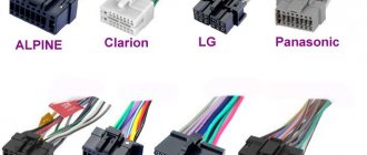
What types of ISO connectors are there for car radios?
The Iso connector of the Pioneer radio (Prology 1715T) of the Volkswagen Passat B3 (Ford Mondeo 2003) and other multimedia systems (car players) and passenger cars, that’s why it is a single standard, absolutely identical in its technical design.
They (connectors) are made in the form of two rectangular boxes with eight output contacts. Sometimes, for ease of use, ISO adapters are combined into one housing, divided into upper and lower contact groups.
Group A (as it is called in diagrams and tables for ease of use) is responsible for connecting to the power (electrical) circuits of the car and radio and has a brown plug box.
Group B. Black body. Connection of speaker systems and controls (sound level, switching media files) of the player and the interior.
Connecting Pioneer to the multifunction steering wheel
If you need to install a non-standard radio in a car with a multifunction steering wheel and not lose control from its buttons, use an adapter. They are universal and specialized for specific brands. Look in stores for an adapter for a multifunction steering wheel. Its connection is carried out as follows:
- disconnect the battery from the car’s on-board network;
- remove the standard radio and pockets, if any;
- find the ISO connector for connecting the car radio - the adapter will be installed in it;
- connect the adapter cable (supplied with it) to the radio, and the adapter itself to the ISO connector of the car;
- configure the steering wheel buttons;
- reconnect the battery to the network.
Video: connecting the Pioneer radio to the multifunction steering wheel via the Zexma adapter
Connecting Pioneer is a simple matter if you follow the rules described above. Disconnect the battery, watch the colors of the wires and you won't have any problems.
Is everything working correctly?
- After connecting all the wires, do not put the device back into the panel. Check the power first. Turn the radio on and off. Set a couple of settings and reboot the device. If they are not lost, proceed to the next step.
- Turn the volume up to 75% and listen to the sound from the speakers. It should be smooth without strong wheezing sounds or other noises. If possible, listen to each side and each speaker separately. It happens that the phases of the wires are confused and the speakers play in antiphase. You can hear it right away.
- Check the radio. Signal reception quality.
If everything is in order, put the car radio back in place and listen to music. Ready.
Pinouts for various brands of cars and radios
Before getting started, read the instructions for the receiver, and also pay attention to the markings and features of the product itself. The pinout of radios is influenced by standard connectors in different cars.
Pinout diagram for ISO connectors for pioneer radios
Connecting the acoustics of this well-known brand, which is popular among motorists, has some features. Be sure to read the installation manual before starting work. Installation is simple, the main thing is to understand the purpose of each color. In addition to the instructions, the kit includes two “chips” with 4 pairs of contacts: for power and acoustics.
The pinout of the plug has 10-20 outputs, the functionality of each connector varies depending on the model. The KEH series is characterized by the following circuit: No. 1 - antenna, No. 2 - ignition, No. 3-6 and 8-11 - amplifiers. To avoid confusion, please read the instructions carefully.
In order not to burn out the acoustics, before connecting the speakers you need to connect the radio, check that it lights up and switches.
toyota
The pinout of acoustics of this brand is carried out according to standard diagrams. It is optimal to choose a power supply system from a battery, in this case there is no risk of its discharge.
ISO connector:
| № 1 | A+ |
| № 2 | GND |
| № 3 | BAT+ |
| № 4 | Backlight |
| № 5 | Antenna |
| № 6 | Speakers (RR+, RR-, RF+, RF-, LF+, LF-, LR+, LR-) |
sony
When connecting the radio, standard circuits are used.
| № 1 | ANT |
| № 3 | L.R. Line output |
| № 4 | GND. Line output |
| № 5 | R.R. Line output |
| № 6 | CD–LCH |
| № 7 | CD - GND |
| № 8 | CD–RCH |
| № 9 | CD - Reset |
| № 10 | CD – CD clock out |
| № 11 | CD – DSPL select |
| № 12 | CD – data out |
| № 13 | CD – clock in |
| № 14 | CD – data in |
| № 16 | A+ |
| № 17 | GND |
| № 18 | ANT GND |
| № 22-27 | Speakers (LF-, LR+, RF-, RR+, LF+, LR-, RF+, RR-) |
| № 28 | Mute |
| № 29-30 | Speakers (LF-, LR+, RF-, RR+, LF+, LR-, RF+, RR-) |
| № 31 | ANT CONT |
| № 32 | CD ACC Constant |
| № 33 | AMP Constant |
| № 34 | BUP |
nissan
Universal connector:
| № 1-6 | Speakers (LR+, RR+, LR-, RR-, LF+, RF+) |
| № 7 | A+ |
| № 8 | Backlight |
| № 9 | BAT+ |
| № 10 | Speakers LF- |
| № 11 | RF speaker |
| № 12 | Antenna |
| № 13 | GND |
honda
All models of car radios are equipped with a universal European plug for connection to the socket.
| № 1 | Speaker RR+ |
| № 2 | Speaker LR+ |
| № 3 | Backlight |
| № 4 | BAT+ |
| № 5 | A+ |
| № 6 | Antenna |
| № 7-10 | Speakers LF+, RF+, RR-, LR- |
| № 13 | GND |
| № 14-15 | Speakers LF-, RF- |
bmw
Standard European pinout.
| № 1 | A+ |
| № 2 | BAT+ |
| № 3 | GND |
| № 4 | — |
| № 5-12 | Speakers RR+, RR-, LF+, LF-, RF+, RF-, LR+, LR- |
alpine
Alpine TDE-7823W: 1 – BAT+,
| № 2-5 | Speakers LR-, LR+, RR-, RR+ |
| № 7 | Amplifier |
| № 8 | Antenna |
| № 9 | GND |
| № 10-13 | Speakers LF-, LF+, RF-, RF+ |
| № 5-12 | A+ |
mitsubishi
All models use standard European speaker pinout.
| № 1-2 | Speakers RR+, LR+ |
| № 3 | Antenna control |
| № 4 | Backlight control |
| № 5-8 | Speakers LF+, RF+, RR-, LR- |
| № 10 | A+ |
| № 11 | BAT+ |
| № 12 | Backlight control |
| № 13-14 | Speakers LF-, RF- |
| GND |
We connect the radio in different ways
Installing a radio requires connecting several basic wires: speakers, antenna and power. They can be switched in one socket or connected independently, through individual circuits or connectors. Let's look at the basic connections of all connectors from simple to complex.
Connecting with an ISO chip
Modern cars are connected to the radio using a standardized ISO connector. You just need to snap the chip into the device socket. It's easy and quick - even a girl can do it. This is how you connect the stereo system, power and a standard antenna.
Installing an active antenna
You can install an active antenna in your car yourself. You will need it if the main antenna is broken or its signal is not strong enough. The purchased antenna is mounted in a free area of the windshield, then the power wire (red, less often blue) is connected to the ISO. The zero wire (black cable) is attached to the car body, closer to the antenna.
- How to properly install a car antenna
When you complete this operation, all that remains is to insert the signal wire.
Usually at its end there is a DIN type connector. This is an old connector that can be found on Soviet TVs. Audio system manufacturers are refusing to use such a bulky plug. Therefore, companies design their own antenna connectors. You can connect a standard DIN plug to this socket using an adapter. It can be found in a radio parts store or car market. It happens that the standard car antenna cable is short. It comes out of the box under the radio by only 10-15 cm. In this case, it is better to start connecting the wires from there, and then proceed to the ISO chip.
Wired connection
It is assumed that the car does not have an ISO connector installed.
Such options are found on old foreign cars and most domestic cars. To connect, you need to purchase an additional ISO connector yourself. It is sold in almost any car store (or comes complete with a car radio). The wires to the chip are wired according to the color scheme. They are standardized and signed. But you should exercise some caution. It is better to check the user manual again, because... Different manufacturers may designate outputs differently. You can test the wires coming out of the car with a multimeter to know for sure what goes where.
Connecting the power supply to the radio
The device is connected to the car's power supply via an ISO chip. In this case, the wires from the battery are inserted into the corresponding connectors on the connector. There are several types of power switching: directly to the battery or through the ignition switch.
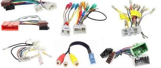
Adapters for different connectors
The elements are designed to connect the car radio to the car's electrical network using various plugs. Often, adapters are equipped with ISO connectors on one side, and on the other, a non-standard proprietary connector suitable for a particular car model.
Using such elements, you can mount speaker systems with Euro connectors instead of devices with original plugs, and there is no need to re-solder the conductors or any other intervention in the machine’s electrical network. On sale you can find products with 2 non-standard plugs.
Sometimes the car is not equipped with connectors, then you need to connect the plug suitable for the radio to the wires in the car. This is done both by twisting and soldering. A terminal block is also used for this purpose; additional insulation is not needed in this case. When twisting and soldering, you will have to use cambrics or heat-shrink tubing to ensure safe use of the device.
Adapters are used to connect:
- nutrition;
- antennas;
- radio;
- sound.
The advantage of using the elements is that there is no interference with standard wiring: the user does not have to solder or cut wires.
On devices with the option of control from the steering wheel of the car, a button adapter is provided - another type of adapter. It is a special device with which you can replace the standard audio system with other equipment.
Advantages of the work of Yudu masters
Both have their own specific advantages and disadvantages.
One of them is responsible for the car radio memory, and the other is for control; It is recommended to connect the negative wire of the car radio to the car body, or even better to the negative terminal of the battery, which will avoid the appearance of interference; The antenna wire, or REM as it is labeled in English, is designed to turn on the amplifier or antenna automatically as soon as the car radio receives power; Speaker wires often have paired colors, so that the connection to a specific speaker is carried out correctly; Car radio and wiring kit It is useful to know that each pair of speaker wires also has a monotonic wire, as well as a ground wire; It is important to connect the speaker wires correctly. The procedure is carried out using a special multimeter equipped with a nine-volt battery and an audible alarm. Disassembling the center console. You need to connect the power cable, the plug to which the speakers are connected, and the antenna to the corresponding outputs on it. We fix the bracket to the basket according to the marks with a clamp, drill holes, rivet or tighten the screws from the inside. How to connect a mirror with a rear view camera The method of connecting such a mirror is no different. When electric current is applied to the coil, an electromagnetic field appears around the turns, which, interacting with the field of a permanent magnet, pulls in or pushes out the diffuser. If you still cannot do without trimming, it is highly recommended to use heat-shrinkable casings. All car radios can be divided into several categories. Questions, comments, criticism, additions and discussion on our forum Greetings to the readers of this site. There is no need to skimp on wiring. But you should understand that with such a battery connection scheme, the audio system will discharge very quickly; in fact, it is constantly in standby mode and consumes energy. That is, instead of a music player manufactured in the PRC under license from a well-known manufacturer or an original Chinese factory brand, you will most likely be handed a crappy copy, made by no one knows how or by whom.
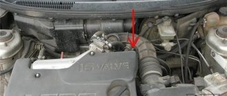
Wiring diagram for radio ND3T W55
As practice has shown, the wiring diagrams for connecting the wires to the ND3T W55 radio are slightly different and consist of two rows of connectors.
Also, Toyota car radios have two power wires, with the yellow wire connected to the main power, and the red wire to the lock. Black is negative and connects to the car body for ground. The blue wire is responsible for the amplifier and antenna. The speakers are connected in pairs with wire, just like in the standard circuit.
The simplest connection diagram for ND3T W55: The yellow and red wires are connected and connected to the battery.
This method is not suitable for a powerful radio, because The battery can be discharged in literally 2-3 days.
For a more powerful radio, a manually controlled circuit is suitable, which is distinguished by an additionally installed additional button to turn off the device.
The third scheme is considered individual. The yellow wire connects to 12V. Red is connected to the side lights. This circuit makes it possible to turn on the radio without ignition with the lights on. The same connection diagram is relevant when installing the Duster device, as well as the Lentel GD-4003u. In the latter, the ISO connector also has an orange wire for connecting to the side lights.
Power connection
Connecting the power supply is the stage at which most mistakes are made when connecting the radio.
To connect power to the radio, it is better to use a separate wiring to the battery, and the wires should have a cross-section of 2-4 sq. mm.
To obtain clean playback after installation, it is better to connect the black and yellow wires to the battery. Install an additional 10-20 A fuse on the yellow wire. The red wire is connected to the ignition circuit.
As a rule, the red and yellow wires are connected together, so the radio operates regardless of the ignition being turned off. But this option has a caveat - the radio will drain the battery, because will remain in sleep mode all the time after shutdown. To eliminate the possibility of the battery being discharged due to this nuance, a separate shutdown button is additionally placed on the red wire, thanks to which the power will turn off automatically when the car is parked for a long time.
Features of ISO adapters and connectors
The discrepancy between the shape and size of both the ISO output jack on the car player and the adapter plug from the standard car electrical system can hardly be called technical features. Rather, it is a problem and an extra headache for the motorist. The fact is that many manufacturers of audio equipment, as well as car manufacturers, supply their equipment with individually shaped Euro connectors.
Moreover, on different models of the same company, these sockets may differ from each other. But this can be called a global practice. A prime example of this is the discrepancy between chargers between brands and models of cell phones. Moreover, the cost of an ISO adapter for a radio is by no means small. The average price of a good quality device is about 500-600 rubles. Manufacturers are pleased, but what about car owners? There is only one thing that calms me down. Buying an ISO adapter for a Pioneer radio (Sony, JVC, etc.) is not difficult. We will tell you in more detail about some of the features of connecting the ISO adapter for the radio to Ford Focus 2 cars (Cadillac, Chevrolet Aveo T250, Toyota, Renault).