What is ISO?
A little theory: the pinout of the ISO connector of the radio is determined by the functionality of the contacts in the plugs, in accordance with their numbering. ISO radio connector is a connector for connecting a car's standard radio, certified according to international standards.
Each of these connectors is designed as an eight-pin rectangular plug, but sometimes they are combined into one housing.
When trying to independently replace, for example, a car player from Pioneer with a JVC, car owners are faced with a situation where the wires in the plug are mixed up or do not even fit the shape of the connectors. In order to solve this issue, you need to buy an ISO plug, which is sold at any auto parts store. After that, pinout the head unit connector according to the diagram.
Pinout of a standard Euro connector
What does a car owner need to know about the pinout of the Euro connector? Let's look at the notation using output 10478 as an example.
Markings and types of connectors
Today, all car radio connectors comply with the ISO standard, and two connectors are used. Each is a plug with eight pins, sometimes the manufacturer can combine them into a single housing. Energy consumption sources are connected to one of them; it is marked with the letter A. As for the second, acoustics, that is, speakers, are connected to it. The connector designation is marked with the letter B.
Adapters for car radio connectors
Head units with three outputs can be found on sale, but they are rare and usually represent an exception.
Even if the connected sockets do not correspond to each other, the car owner has several connection options:
- You buy a special adapter for the radio, which can be connected to the outputs of the speaker system.
- The second method is considered “collective farm” among car enthusiasts. Its essence is to cut off the non-standard output and wind the necessary wires to it. But we do not recommend using this option, because eventually the wires will begin to unwind, so the “collective farm” procedure will have to be repeated. In addition, the cost of adapters is not so high to use this method.
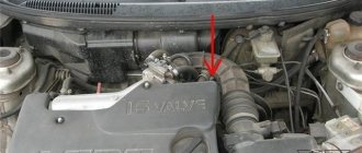
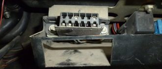
Upper power connector "A"
As already reported, this output is intended for connecting power supplies to the electrical circuit of the vehicle.
| 1 | Not involved |
| 2 | Not involved |
| 3 | Not involved |
| 4 | Regular meals |
| 5 | To connect the antenna |
| 6 | To connect the backlight |
| 7 | To connect the ignition |
| 8 | Vehicle weight |
Pinout and pin designation
And although the device is equipped with eight contacts, all of them can not be used to connect the head unit. But these contacts would not exist if they did not perform certain functions. The first three outputs, as well as the sixth, are rarely used, especially for connecting budget device options. Typically, their use is due to the need to connect additional functionality, and we are talking about more advanced car radios. Please note that contact colors may vary.
If we talk about additional options, we mean:
- ANT output. This pin is used if the vehicle is equipped with a retractable antenna.
- Remote function, thanks to which external amplifiers can be connected to the head unit. This will increase the number of connected speakers. This is relevant for music lovers and owners of vehicles with a large interior, which, with proper installation of the speakers, will increase the sound quality.
- Illumination function. This option allows you to automatically change the brightness and color settings of the head unit display. If the car is moving at high speed, the screen brightness will drop so that the system does not distract the driver from driving the car. When the vehicle stops, the radio will return to the initial settings.
- Mute function. Today, many head units have this option. But this option can be activated either by clicking on the corresponding button or automatically. In particular, if an impulse from a mobile device passes through the head unit receiver, the system will automatically lower the volume so that the driver can talk on the phone without being distracted from driving.
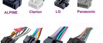
Connectors for radio tape recorders from different brands
The fourth contact is responsible for powering the vehicle's audio system. The wire from it must be connected to the ignition switch terminal and powered from the battery, but for this you should also use a fuse. This method of connecting the wiring will protect the battery from discharge, since activation of the head unit is possible after the key is turned in the ignition.
The fifth contact is for connecting the antenna wire. As for the seventh contact, it is important because it is responsible for powering the volatile memory of the head unit. That is, if it accidentally turns off, this will reset all settings of the car radio. It’s unlikely that anyone will like losing all the parameters after setting it up.
It is necessary that each of the power cables be protected by a fuse for safety purposes. If malfunctions sometimes occur in the operation of the audio system, it is advisable to install a capacitor between the seventh and eighth outputs. As for the capacitor capacity, this parameter must be selected individually. The capacitor performs a filtering function, that is, the element is designed to smooth out various fluctuations in the on-board network.
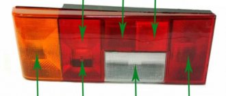
Bottom speaker connector "B"
As mentioned earlier, speakers are connected to output B.
As for the pinout of contacts, their designation is as follows:
| 1 | Plus for rear right speaker | Indicated in lilac color |
| 2 | Minus for him | Lilac-black |
| 3 | Positive output for the right front speaker | Indicated in gray |
| 4 | Minus for the same speaker | Indicated by gray and black colors |
| 5 | Positive output for front left speaker | White contact |
| 6 | Negative output for the same column | Black and white color |
| 7 | Positive contact for rear left column | Indicated in green |
| 8 | Minus output for her | Black-green |
Most head units are designed to work with four speakers; eight wires are used for this, two for each speaker. Note that the quality of the audio track is determined by the correct connection of the plus and minus. If the flattening is mixed up, nothing will happen, but the car radio will function abnormally, and the sound quality will not be as good.
If you are the owner of a car with a radio that only plays cassettes, do not rush to buy a new audio system with a USB output. Today you can find such a device as a cassette adapter for a car radio. It looks like a cable cassette and is simply inserted into the connector. The cable connector is connected to a mobile phone or player, and you can listen to music in digital format.
Head unit connector pinout
One of them is the antenna. But don’t be upset, because to install and connect the car radio, you need to find the right connector in the store and use the instructions to connect the radio to the car.
To connect a passive one, just insert its plug into the socket. A good solution would be to purchase stranded copper wires with silicone insulation. Also in each bundle there is a wire without a plus strip and with a minus strip.
Done, you got rid of the old device - you can install a new one. Connecting speakers This procedure is carried out carefully and carefully, since not only the purity of the sound depends on this, but also the operation and durability of the radio and speakers.
As for the ISO connectors, they are much more convenient. Next are the connectors.
The described circumstances are a sign of incorrect phasing. With this connection, the PG works constantly, and if the car is parked for a long time, you can simply press the button and stop power from the battery. Detailed car radio connection diagram First, you should understand the connection of the black and yellow wires. How to find the wire pinout and connect the MYSTERY MCD 664MPU car radio without a chip
How to connect a radio in a car
Usually, the way the wires are located is how you need to connect the speakers, that is, the front two pairs of lighter wires go to the front speakers, and the rear wires to the rear speakers. Since installation difficulties arise precisely in the absence of an ISO adapter, all wires must be stripped and then insulated.
In addition, such a circuit consumes much more electricity.
This method is not the best, but it is very often used not only by car enthusiasts, but also by car repair shops. The connection of the audio system and car wires is carried out in accordance with the color marking.
Disconnect the battery, watch the colors of the wires and you won't have any problems. Plus right front speaker; Green with stripe marking RL-. Also, more expensive models have an LCD display, support for watching videos, watching TV channels, a navigation system and many more interesting functions.
They have paired colors. Therefore, it is worth thinking about what is more important: the operation of the radio independent of the ignition switch or the long-term operation of the battery?
How to install a car radio
Plus left rear speaker; Purple with stripe marking RR-. If you have an idea about the electrical equipment of a car, connecting wires and a little accuracy in work, then you can make the connection yourself. To connect a passive one, just insert its plug into the socket.
As you can see, connecting a car radio based on the color of the wires is not difficult and, if done carefully, will take no more than hours. There is no power lead out or it was done incorrectly. Working with 2 din car radios The process is similar, but there are several nuances.
All the necessary wires for installation are supplied and connected to the connector, however, the plug does not fit into the car radio socket. A special diagram will help us with this, on which you can see which wires are responsible for what and where they go.
Installing a radio
Standard devices do not always satisfy the requirements of users, so they are replaced with radios selected to suit their taste.
Car radio installation
Previously, installing a radio caused quite a lot of problems, due to the fact that each manufacturer, be it the expensive Pioneer or the cheap Saundmax, used their own connection standards, and you had to cut into the car wiring diagram to install the connector. Recently, there has been standardization in this process; many manufacturers are introducing the so-called euro feature.
Radio socket
That is, you need to connect the mating part to the car circuit once and then simply remove the radio tape recorder and install another one. If you purchased a fairly “new” car, then this connector may have already been installed by the manufacturer. if it is not there, then it’s okay, the work of installing it is not particularly difficult, you can do without the services of an auto electrician, spending a couple of hours and doing everything yourself.
Car radio connectors
Radio connection block - pinout and diagram
You must first purchase a Euro connector from stores that sell musical accessories for cars. Next, you need to remove the old car radio from its installation location; special keys may be needed for this. If you bought a new radio, then, as a rule, these keys are included in the kit. Otherwise, you will have to purchase the tool. The price of the issue is in the range of 100-150 rubles, but you will save a lot of nerves and protect the car from unpleasant scratches and damage.
Car radio connection diagram
After removing the radio, figure out the wires. Typically, each speaker has two wires of the same color, the negative wire is additionally marked with a black line. For better sound quality, it is important to observe the polarity of connecting the speakers to the radio.
Modern systems usually use 4 speakers, therefore you should have 4 pairs of wires from them of different colors.
Radio wires
You need to deal with the power wire. Typically, a red wire with a fuse installed in the gap is used for the positive contact. It looks like a cap from a ballpoint pen, in a white plastic case.
If you don’t have it, be sure to install it, which will allow you to avoid possible troubles with the car’s wiring in the event of a short circuit in the radio or chip.
In addition to the positive one, of course, there is also a negative wire, which can be blue or black. Some radio models also have a separate power supply for the device's memory.
Radio connection diagram
On the universal block, the wires are also separated by color, and already have trimmed insulation at the ends. It is recommended to tightly twist or better solder them with the wires in the car after putting on heat-shrinkable tubes for insulation.
If you don’t have cuttings at hand, you can get by with PVC electrical tape. After carefully insulating all connections, we can safely say that the most inconvenient part of the job is over. If during the process of stripping the wires one of them comes off, then you can build it up with a piece of wire, preferably of a suitable color.
Completion of work
Next, we move on to connecting the radio with the second part of the block. First, you need to find a diagram of the radio socket in the operating instructions or on the Internet. The correct pinout of the radio block is very important.
According to this diagram, we connect the wires by color, be sure to insulate them and, without putting the radio in place, check that all speakers are turned on and sound. Do not forget to connect the separately located antenna wire connector, the radio tuner will not work.
If you fail to turn on the radio the first time, check all the wire connections again and check the supply voltage. After eliminating the errors, check the activation again.
Standard connection diagrams
Possible problems and their solutions
The first problems may arise during the installation of equipment. If the radio does not fit completely into the landing shaft, then you should check the possibility of placing the housing in the instrument panel. Some cars require trimming of the internal structural elements into which the plugs or the rear wall of the device rest. The defect occurs due to jamming of the side latches (deformation or dirt ingress).
When using the device, there may be loss of sound from the speakers due to poor contact in the connecting cables. To restore functionality, you need to disconnect the plugs, inspect the connection points and reconnect the Pioneer radio. The defect occurs when the channels of an external amplifier break down; it is recommended to connect the speaker directly to the player. The damaged amplifier is repaired in a specialized service.
Doesn't turn on
If the head unit does not turn on when you press the keys, then you need to turn off the ignition and check the correct operation of the power circuits and the reliability of the cable connections, as well as the connection diagram of the Pioneer car radio. If you use an infrared remote control to start, the transmitter may not work due to dead batteries. Additionally, it is worth checking the functionality of the buttons; if dirt or moisture gets on the contacts, the transmission of signals that control the operation of the audio player is disrupted.
Doesn't turn off
Some Pioneer radios have an original operating algorithm that does not allow turning off the power when the demo mode is active. An attempt to turn off the equipment puts the player into demo mode, which is turned off by removing the front panel. After disabling the function through the menu, pressing the button turns off the power to the head audio unit (except for memory support).
A car radio, head unit, is a multimedia component that provides a single system interface for various media components. The head unit is central to the sound system and is usually located in the center of the dashboard.
Standards 1DIN and 2DIN
All car radios can be divided into two types, which are installed by car manufacturers.
- 1DIN standard (single block);
- 2DIN standard (two-block).
Cars of European brands prefer 1DIN.
| №1 | Empty |
| №2 | Empty |
| №3 | Empty |
| №4 | Constant power |
| №5 | Antenna power |
| №6 | Backlight |
| №7 | Ignition |
| №8 | Weight |
And Japanese, American and a number of Chinese car brands use the 2DIN standard.
| №1 | Rear right "+" | Purple, "B1" |
| №2 | Rear right "-" | Purple black, “B2” |
| №3 | Front right "+" | Gray, "B3" |
| №4 | Front left "-" | Grey-black, "B4" |
| №5 | Front left "+" | White, "B5" |
| №6 | Front left "-" | White-black, "B6" |
| №7 | Rear left "+" | Green, "B7" |
| №8 | Rear left "-" | Green-black, "B8" |
Useful: Pinout of contacts for car engine ECU connectors
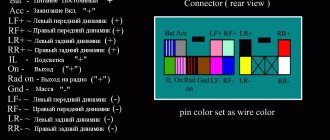
Standard form of wiring connections
Upper part of the connector (socket numbers and wiring colors):
- Changing the sound volume when the car is moving - a free-color wire.
- Muting the sound (MUTE) when there is an incoming phone call - a free-color wire.
- Empty nest.
- ACC - power supply 12 volts - wire color yellow.
- Power supply for the radio antenna (12V) - wire color is blue.
- Car radio display backlight - wire color is orange.
- Turning on the ignition - the wire color is red.
- Ground (grounding) - wire color is black.
- Increasing the volume of the right rear speaker - color purple.
- Reducing the volume of the right rear speaker - purple and black.
- Increase the volume of the right front speaker - gray color.
- Reducing the volume of the right front speaker - gray and black.
- Increase the volume of the left front speaker - color white.
- Reducing the volume of the left front speaker - white and black.
- Increase the volume of the left rear speaker - color green.
- Reducing the volume of the left rear speaker - green and black.
The official name of the pinout is ISO 10487 (Euro connector).
Pinout diagrams for ISO connectors for Pioneer radios
The model name of the Pioneer car radio, the connection diagrams of which are shown above, can be found out from the file name of each diagram.
Remember: when connecting the device for the first time, you first need to supply power to the radio, and if it lights up and switches as expected, connect the speakers. Otherwise, you can burn not only your audio player, but also your expensive car speakers.
Pinouts for various brands of cars and radios
The wiring of the linear outputs on the standard radio depends on the make of the car and the head unit.
Before pinouting the connectors of the car radio, you must read the information presented on the cover of the device and in the instructions for it.
Toyota
For a standard plug: 1 - A+, 2 - GND, 3 - BAT+, 4 - backlight, 5 - antenna adjustment, 9-16 - speakers (RR+, RR-, RF+, RF-, LF+, LF-, LR+, LR -).
Universal connector for most models: 1 - ANT, 3 - linear output LR, 4 - GND linear outputs, 5 - linear output RR, 6 - CD in LCH, 7 - CD in GND, 8 - CD in RCH, 9 - CD reset , 10 — CD clock out, 11 — CD DSPL select, 12 — CD data out, 13 — CD clock in, 14 — CD data in, 16 — A+, 17 — GND, 18 — ANT GND, 22-27 and 29- 30 — speakers (LF-, LR+, RF-, RR+, LF+, LR-, RF+, RR-), 28 — CD mute, 31 — ANT CONT, 32 — CD ACC CONT, 33 — AMP CONT, 34 — B UP .
Nissan
Standard circuit: 1-6 - speakers (LR+, RR+, LR-, RR-, LF+, RF+), 7 - A+, 8 - backlight, 9 - BAT+, 10 - LF- speaker, 11 - RF- speaker, 12 - antenna control, 13 - GND.
Honda
Standard connector: 1 - RR+ speaker, 2 - LR+ speaker, 3 - backlight, 4 - BAT+, 5 - A+, 6 - antenna control, 7-10 - speakers (LF+, RF+, RR-, LR-), 13 - GND , 14-15 - speakers (LF-, RF-).
Universal connectors: 1 - A+, 2 - BAT+, 3 - GND, 4 - empty, 5-12 - speakers (RR+, RR-, LF+, LF-, RF+, RF-, LR+, LR-).
Alpine
Alpine TDE-7823W: 1 - BAT+, 2-5 - speakers (LR-, LR+, RR-, RR+), 7 - amplifier control, 8 - antenna adjustment, 9 - GND, 10-13 - speakers (LF-, LF+ , RF-, RF+), 16 - A+.
Alpine 7190M: 2 - amplifier control, 8 - GND linear outputs, 9-10 linear outputs (R, L), 13 - antenna, 27-28 - speakers (LR+, LR- and LF-, LF+), 29 - GND, 31 - BAT+, 32 - A+, 34-36 - speakers (RR+, RR- and RF-, RF+).
Mitsubishi
For all models: 1-2 — speakers (RR+, LR+), 3 — antenna, 4 — backlight+, 5-8 — speakers (LF+, RF+, RR-, LR-), 10 — A+, 11- BAT+, 12 — backlight, 13-14 — speakers (LF-, RF-), GND — connector rim.
Kenwood KDC KRC
There are several options for pinout of the radio chip from this manufacturer, depending on the model of the device:
- KDC5040R and others: 1 - GND, 2 - A+, 3 - antenna, 5-8 - speakers (RF+, RF-, LF-, LF+), 9 - BAT+, 10 - backlight, 11 - TEL mute, 12 - EXT AMPL CONT, 13-16 - speakers (RR+, RR-, LR-, LR+).
- KRC155D: 1 - GND, 3 - A+, 5 - BAT+, 8-9 - speakers.
- KDC84R and others: 1 - input A, 2 - GND input A, 7-10 - linear outputs (L, R, R, L), 11 - input A, 17-20 - GND linear output (L, R, R , L), 25 - GND, 26 - A+, 27 - amplifier, 33 - BAT+, 34 - backlight.
- KRC752R: 1 - ANT GND, 4 and 28 - output L, 5, 18, 27 and 39 - GND outputs (L, R, L, R, respectively), 8 - backlight, 9 - BAT, 10-13 - speakers (LR -, LR+, LF+, LF-), 14 — ANT, 17 and 40 — output R, 20 — antenna, 21 — A+, 22 — GND, 23-26 — speakers (RR-, RR+, RF+, RF-), 36 and 48 - phone interface.
What are the wires used for and where do they go?
Types of USB connectors
Wires for car radios are used to connect to a power source, speakers and amplifier, remove control signals and implement service functions. Thanks to clear identification by color, the likelihood of making a mistake when connecting is reduced, since it is clear which wires go where and what they are needed for.
Orange
The orange wire (ILL) is most often used to control the backlight of the car radio display. It connects to the parking light switch. In this case, several backlight control scenarios are possible. For example, you can make its brightness automatically decrease when the side lights are turned on.
Yellow and red
According to the generally accepted standard, the yellow and red wires are used to connect the positive pole of the power supply to the car radio. Through the first of them, constant power is provided to the device’s microcircuits along with the audio power amplifier and display backlight. When voltage is applied to the yellow cable, all functions of the car radio begin to work. Often, its break is connected to a fuse in a housing that matches the type. The higher the output power of the car radio, the higher the rating of the fuse link.
The red wire, constantly connected directly to the battery, provides continuous power to the volatile memory chip, which stores radio stations recorded by the owner, car radio parameters and the place where listening to music from the media was stopped. The yellow wire is often connected not directly to the on-board network, but through the ignition switch. Thanks to this approach to power supply, the current consumed by the receiver is reduced several times.
Blue and pink
The blue wire is used by some manufacturers to control a motorized antenna. It is supplied with power when the radio mode is turned on. When the radio is turned off, the antenna is automatically retracted, since it contains an additional relay, which is powered directly from the battery. Another purpose of blue is to enable additional functions. For example, the Reverse wire on the radio is used to activate the parking sensors or rear view camera mode.
Pink is used to implement various service functions. One of them is blocking multimedia functions on a 2-din radio with a video player. The control signal is most often supplied from the warning lamp switch under the parking brake lever. As soon as the pink cable is connected to ground, it becomes possible to start the video player or turn on the TV tuner. Otherwise an error message will appear on the display.
Blue - white
The blue-white cable (blue wire with a white stripe) is designed to control the power of the active antenna. It is often marked with a tag marked “Remote”. This cable also supplies a control signal to the car amplifier. The connection can be made either directly to the device or through a special relay.
What wires to use to connect the car radio
To begin with, a typical diagram for connecting a radio with color pinout of wires is given. It is standard, but may vary in some colors for connecting speakers. This is to make it clear what the conversation is about.
Typical radio connection diagram
A diagram with the purpose of the wires and their color is shown on the top cover of almost every radio. It can be in both Russian and English. Where everything is more or less clear, but if it is given in English, then here are some explanations:
- FRONT - frontal (side).
- REAR - rear, rear.
- LEFT - left.
- RIGHT - right.
- +12 V, Battery, Memory, YELLOW - yellow power wire. It goes to the amplifier through a fuse; it is needed to power the memory, that is, to save settings. But it is advisable to install another fuse 30 centimeters from the battery to protect the wire and device;
- ACC, DC12V, RED - red. Controls switching on. On modern cars there is a key position in which all systems are de-energized except for some. The operation of a multimedia system is one of them.
- GND - black, body or minus of the car.
- GREEN - green.
- GRAY - grey.
- WHITE - white.
- BLUE - blue.
- BROWN - brown.
The first thing you need to do is stretch the wires, power, controls and audio systems. The wires must be reliable, with good insulation and with a selected cross-section.
The power supply of 12 - 13 volts is small, but the currents are solid. With a conventional audio system, it is assumed that there are a couple or two speakers, the current consumption will be up to 10 A. Most tape recorders have a 10 ampere fuse.
Which cable to connect the car radio to power
First. When choosing wires, look at the wire cross-section. The table below shows the correspondence between the conductor cross-section and fuse current, and for comparison, in the American measurement system (AWG).
Table for selecting wire cross-section based on fuse current
With a fuse current of 10 A, according to the table, 1 mm² is sufficient. Mathematically, everything is correct, but I assure you this is not enough. By stretching a wire with a cross-section of 2.5 mm² at full volume, you will see a decrease in the brightness of the radio backlight.
It's all about cable resistance. To connect a tape recorder from a battery you need at least 2 meters of wire. And even though copper has the smallest resistivity, it still has an effect. Take stranded copper wire with a cross section of 4 - 6 mm².
There are also silver wires, but they are very expensive. Don't even try Chinese aluminum ones.
The second important point is isolation. It should be thick and flexible at the same time. And it is better if it is a cable rather than a wire. Cables with the same cross-section have a stronger sheath. For flexible cables, the first position in the marking may be the letter “G”, which indicates that the cable is multi-core and flexible. For example, KG is a flexible cable. Has rubberized insulation.
Example of a reliable connection to the battery output
To connect the car radio, it is more convenient to use multi-core wires. All connection points are in different places, so two or three wires are not needed.
Accelerating Code: Tiles and Barriers
You can gain additional acceleration by using tiling. Tiling divides the threads into equal rectangular subsets or tiles. You determine the appropriate tile size based on your data set and the algorithm that you are coding. For each thread, you have access to the global location of a data element relative to the whole or and access to the local location relative to the tile. Using the local index value simplifies your code because you don't have to write the code to translate index values from global to local. To use tiling, call the on the compute domain in the method, and use a tiled_index object in the lambda expression.
In typical applications, the elements in a tile are related in some way, and the code has to access and keep track of values across the tile. Use the tile_static Keyword keyword and the to accomplish this. A variable that has the tile_static keyword has a scope across an entire tile, and an instance of the variable is created for each tile. You must handle synchronization of tile-thread access to the variable. The stops execution of the current thread until all the threads in the tile have reached the call to . So you can accumulate values across the tile by using tile_static variables. Then you can finish any computations that require access to all the values.
The following diagram represents a two-dimensional array of sampling data that is arranged in tiles.
The following code example uses the sampling data from the previous diagram. The code replaces each value in the tile by the average of the values in the tile.
Shaping and Indexing Data: index and extent
You must define the data values and declare the shape of the data before you can run the kernel code. All data is defined to be an array (rectangular), and you can define the array to have any rank (number of dimensions). The data can be any size in any of the dimensions.
index Class
The index Class specifies a location in the or object by encapsulating the offset from the origin in each dimension into one object. When you access a location in the array, you pass an object to the indexing operator, , instead of a list of integer indexes. You can access the elements in each dimension by using the or the .
The following example creates a one-dimensional index that specifies the third element in a one-dimensional object. The index is used to print the third element in the object. The output is 3.
The following example creates a two-dimensional index that specifies the element where the row = 1 and the column = 2 in a two-dimensional object. The first parameter in the constructor is the row component, and the second parameter is the column component. The output is 6.
The following example creates a three-dimensional index that specifies the element where the depth = 0, the row = 1, and the column = 3 in a three-dimensional object. Notice that the first parameter is the depth component, the second parameter is the row component, and the third parameter is the column component. The output is 8.
extent Class
The extent Class specifies the length of the data in each dimension of the or object. You can create an extent and use it to create an or object. You can also retrieve the extent of an existing or object. The following example prints the length of the extent in each dimension of an object.
The following example creates an object that has the same dimensions as the object in the previous example, but this example uses an object instead of using explicit parameters in the constructor.
Features of ISO adapters and connectors
The discrepancy between the shape and size of both the ISO output jack on the car player and the adapter plug from the standard car electrical system can hardly be called technical features. Rather, it is a problem and an extra headache for the motorist. The fact is that many manufacturers of audio equipment, as well as car manufacturers, supply their equipment with individually shaped Euro connectors.
Moreover, on different models of the same company, these sockets may differ from each other. But this can be called a global practice. A prime example of this is the discrepancy between chargers between brands and models of cell phones. Moreover, the cost of an ISO adapter for a radio is by no means small. The average price of a good quality device is about 500-600 rubles. Manufacturers are pleased, but what about car owners? There is only one thing that calms me down. Buying an ISO adapter for a Pioneer radio (Sony, JVC, etc.) is not difficult. We will tell you in more detail about some of the features of connecting the ISO adapter for the radio to Ford Focus 2 cars (Cadillac, Chevrolet Aveo T250, Toyota, Renault).
Euro and ISO sockets and working with them
Experts call power connectors not chips, but sockets. This term comes from electronics and refers to the connection location. The pinout is also a way to connect an electronic device to the vehicle's on-board system. At the same time, the layout of the radio chip may differ for cars, for example, Toyota, Mitsubishi or Volvo, as well as for model brands - Sony, Pioneer, JVC and others.
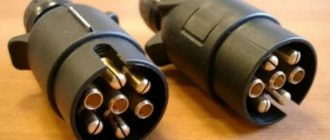
EURO ISO car radio connector
Please note that adapters for the Euro connector are available for all car radios; this helps to avoid problems with pinout and allows you to unify and protect the “native” connections from damage when disconnected. It is these connectors that are usually called chips, although the term allows for a much broader interpretation. The Euro connector is also classified as an ISO connector.
Chips (connectors, adapters, adapters) for connecting radios
Connecting a car radio if there is an ISQ connector
The general standardization of recent decades is not such a bad thing. If you have a relatively new car, it most likely has a block near the “seat” for the car radio for connecting it. It is made according to the ISQ standard and connected to the car’s electrical/audio system. In this case, connecting the car radio is the simplest - connect two connectors and everything should work. True, you need to know which connector on the car to install the adapter in, but this should be in the description of the car... Or you can try to understand it by the inscriptions next to the sockets.
The car radio should include an adapter for the ISQ Euro connector.
If the car radio does not have such an output, then it needs an adapter from the standard connector to ISO. More or less serious manufacturers make such a connector or there is an adapter included with the radio. If you don’t have it, you can buy it or you will have to look for it exactly for your brand/model of radio, which is problematic.
ISO connector
It is much easier to purchase an adapter and, guided by the colors and pattern given on the cover, hook up the radio.
Pinout of the ISQ Euro connector for connecting a car radio
You can, of course, connect the radio without a plug. It is enough to understand the terminals on it and connect (or stretch the wires to the speakers) without confusing the plus and minus of the speakers with the amplifier outputs. However, using a chip simplifies the connection when you need to replace the radio.
How to properly connect to an electronic device
The concept of an interface as we know it today dates back to the 1960s. More precisely, in 1964, when the company developed its legendary IBM System/360 mainframe. It was then that the main tasks of any interface - physical or virtual - were formulated. They were to provide a standard connection for all devices.
Euro connectors
Initially, only a few types of standard inputs could be made to ensure compatibility between products from different manufacturers. This was a PS/2 port for the keyboard, an LPT port for the printer, and a connector for the PCI card. Nowadays, each type of connection has its own standard interface; this approach greatly simplifies the development and sale of any type of device and allows you to understand their built-in capabilities. Here are descriptions of the main communication elements, first of all, the designation of the button on the radio, which are used on the panels of Pioneer and other car radios.
Types of branded connectors
Description of the buttons on the front panel of the radio for control (decoding)
| Button labels | Button function |
| A.F. | Different RDS frequency, automatic search when reception is poor |
| ALL OFF | Everything is off |
| AMS | Music sensor, works on the principle of playing a number of tracks equal to the number of clicks |
| ANG | Panel adjustment |
| ATA | The radio turns on automatically when you turn off and rewind media tracks |
| A.T.T. | Quickly reduces volume |
| BAND | Selecting a radio receiver |
| BEER | Enabling sound when pressing buttons |
| Blank Skip | Skips pauses longer than 8 seconds |
| BMS | Compensates for low frequencies when dropped due to the main device |
| BTM | Remembers the quality frequency of strong stations |
| CLK ADJ | Adjusts time |
| COLOR | Color |
| DISP | Display activation |
| DNPP | Selecting a CD in the changer |
| DNPS | Entering disc names |
| DSP | Activating the sound processor |
| EJECT | Remove the cassette from the cassette receiver or disc |
| EON | Reception of traffic information |
| FUNCTION | Switches the most used functions |
| INTO SCAN | Plays the recording for 10 seconds to search |
| LOS | Looks for stations, skipping with weak reception |
| LOUD | Tone compensation |
| M.RDM | Disc random playback |
| P.I. | Automatic search |
| PI SOUND | Switching to another frequency |
| PI MUTE | Muffled sound |
| POWER | Shutdown |
| PS | Listening to saved settings |
| PTY | Selecting a genre |
| RDS | Search for a station by metadata |
| RDM | Play disc tracks in any order |
| REG | Switching to the frequency of a radio station with RDS |
| Repeat Play | Replaying a track |
| SCAN | Scanning tracks and playing the beginning |
| SEL | Settings |
| SHUFFLE PLAY | Play available music in random order |
| SYSTEM Q | Tracking sound enhancement factors and showing them on the display |
| TA SEEK | Searching for a station with RDS |
| TC | Calling the tuner when rewinding |
Car radios without a plug: determining the pinout
The following option can be considered a more complex problem. When the connector to the board is simply missing, along with the documentation. What to do in this case? There is one working way to solve this problem. The chip for connecting the car radio may be lost, the location of the pins is inaccessible, but the correct circuit can be determined.
Car radio connectors
This can be done in any radio, both elite ones - JVC, Pioneer, Sony, and branded ones, for example, Toyota. It is easier to determine the location of pins on a radio of a well-known brand than on an unknown one. The same situation is with domestic VAZs. The pinout can be found freely on the Internet.
The problem is with car radios with an exotic manufacturer and the same exotic connector. Moreover, in some cases, the connector may differ not only between models, but also between batches. For these purposes, you will need a multimeter, which you will need to connect and “ring” the contacts.
Determining the power wires
First you need to find the power wires: “yellow” and “black”. The yellow wire is found as follows. In most cases, the “yellow” and “black” power pins are larger in diameter and stand out well from the others. But sometimes this may not be the case.
Power cables
The “negative” one is usually looped onto the body of the car radio, respectively, if one contact of the multimeter is connected to the body, the other to the terminal. “Minus” will ring the contact. The other one will be a “plus”.
Finding the control red wire
To find the control “red” wire, you will need to connect a 500-800 Ohm resistor. Also use a 12 V power supply, connect the negative wire to the case, the positive wire to the plus defined in the paragraph above. Turn on the power supply. Then connect one resistor output to positive, the other to all remaining contacts, but on the board due to the limited length of the resistor. The car radio will turn on at the desired contact.
Conclusions to the speakers
Next you need to find the leads going to the speakers. Usually they are displayed on contacts:
- front left, front right;
- rear left, rear right.
We are talking about paired contacts at the beginning or end of the connector. On the plan you need to find the amplifier chip. Speaker leads can be determined by the width of the tracks; they are usually one of the widest. Using a multimeter, you can determine which speaker is right and which is left. This is well commented on in the video, which shows all the mentioned elements of the microcircuit and clearly explains the nature of the connector and how to restore it.
Multimeter
Peculiarities
So, let's summarize. First of all, there is always the opportunity to use a Euro connector and forget about the difficulties of switching from a unique circuit. If it is missing, the location of the contacts is determined empirically by ringing the contacts. First there is power, then the control wire, then the speakers. After identifying all the contacts, the chip for connecting the radio is made independently.
Branded car radios such as Toyota or JVC have all types of plugs publicly available. An ISO adapter can also be purchased for connection to them.
Connectors for car radios
Conclusion
Using the described method, you can safely connect a radio without a chip; this makes it possible to revive almost any device without a plug. This feature helps you save on the purchase of more expensive models that are not sold complete. The restoration process will not cause difficulties even for people without experience in the field of electrical engineering and electronics. You can connect everything yourself, this is a huge advantage of the proposed method.
We invite you to watch the full video on this topic; after watching, any feature on a Pioneer or Toyota radio will become clear.
You need a chip for the Autofun DVA 3510U car radio, price and price.
ISO is used as the generally accepted European standard for connecting car radios. The pinout of the radio is carried out in accordance with it.
general information
Do-it-yourself repair of Chinese pioneer car radios
AMP is a technology for accelerated mobile pages, which is developed by independent developers and actively promoted by Google in its search engine. Yandex has not yet joined this initiative, but I am sure that soon they will either implement this standard or come up with something similar in operating principle.
The bottom line is that the site uses special tags, the number and functionality of which are strictly limited. The developer's task is to assemble a hodgepodge of available schemes that will solve the customer's problem.
Pages with AMP rank higher than other queries in search due to the fact that they meet the requirements for fast loading and are adapted for mobile devices.
In fact, all such pages are static or conditionally dynamic, since they allow the use of form submissions, as well as iframes.
Next, I’ll tell you about the main features of AMP.
Installing a radio
Standard devices do not always satisfy the requirements of users, so they are replaced with radios selected to suit their taste.
Car radio installation
Previously, installing a radio caused quite a lot of problems, due to the fact that each manufacturer, be it the expensive Pioneer or the cheap Saundmax, used their own connection standards, and you had to cut into the car wiring diagram to install the connector. Recently, there has been standardization in this process; many manufacturers are introducing the so-called euro feature.
Radio socket
That is, you need to connect the mating part to the car circuit once and then simply remove the radio tape recorder and install another one. If you purchased a fairly “new” car, then this connector may have already been installed by the manufacturer. if it is not there, then it’s okay, the work of installing it is not particularly difficult, you can do without the services of an auto electrician, spending a couple of hours and doing everything yourself.
Car radio connectors
Adapters for different connectors
The elements are designed to connect the car radio to the car's electrical network using various plugs. Often, adapters are equipped with ISO connectors on one side, and on the other, a non-standard proprietary connector suitable for a particular car model.
Using such elements, you can mount speaker systems with Euro connectors instead of devices with original plugs, and there is no need to re-solder the conductors or any other intervention in the machine’s electrical network. On sale you can find products with 2 non-standard plugs.
Sometimes the car is not equipped with connectors, then you need to connect the plug suitable for the radio to the wires in the car. This is done both by twisting and soldering. A terminal block is also used for this purpose; additional insulation is not needed in this case. When twisting and soldering, you will have to use cambrics or heat-shrink tubing to ensure safe use of the device.
Adapters are used to connect:
- nutrition;
- antennas;
- radio;
- sound.
The advantage of using the elements is that there is no interference with standard wiring: the user does not have to solder or cut wires.
On devices with the option of control from the steering wheel of the car, a button adapter is provided - another type of adapter. It is a special device with which you can replace the standard audio system with other equipment.